• Skip to primary navigation
  • Skip to main content
  • Skip to primary sidebar
  • Skip to footer

3D CAD World

Over 50,000 3D CAD Tips & Tutorials. 3D CAD News by applications and CAD industry news.

  • 3D CAD Package Tips
    • Alibre
    • Autodesk
    • Catia
    • Creo
    • Inventor
    • Onshape
    • Pro/Engineer
    • Siemens PLM
    • SolidWorks
    • SpaceClaim
  • CAD Hardware
  • CAD Industry News
    • Company News
      • Autodesk News
      • Catia News & Events
      • PTC News
      • Siemens PLM & Events
      • SolidWorks News & Events
      • SpaceClaim News
    • Rapid Prototyping
    • Simulation Software
  • Prototype Parts
  • User Forums
    • MCAD Central
    • 3D CAD Forums
    • Engineering Exchange
  • CAD Resources
    • 3D CAD Models
  • Videos

Mike Santora

Verisurf Quality Inspection Suite

May 3, 2017 By Mike Santora Leave a Comment

Verisurf-software-screen-shot-imageVerisurf Software, Inc. has announced the availability of its Quality Inspection Suite, a combination of popular Verisurf application modules configured to provide an efficient quality inspection and reporting solution. Quality Inspection Suite provides a cost-effective package and flexible purchase options to match the needs of individual customers, including site license and subscription options.

Verisurf Quality Inspection Suite is made up of select application modules, including:

Verisurf CAD – capable of reading all native CAD file formats, allowing customers to work with any CAD model – solid, surface or wireframe. Model-based Definition (MBD) lets users set unique IDs, tolerances and GD&T constraints in the model for any surface, feature or other critical inspection item. Verisurf Device Interface (VDI) insures device compatibility and controls all digital measuring devices.

Verisurf Measure – provides measurement of features from precise single points to scanned point clouds. A virtual image of the measuring device is graphically displayed on screen, while smart tools automatically recognize and display features during the measuring process, making it easy to learn and use.

Verisurf AUTOMATE – programs and operates all types and brands of coordinate measuring machines with an intuitive 3D experience, visual object oriented programming and open standards increase freedom of choice while reducing costs.

Verisurf Validate – provides precise CAD model translation validation by comparing the authority CAD model to the translated CAD model, this enables customers to quickly identify any translation error.

Verisurf Software
www.verisurf.com

Filed Under: Software Tagged With: verisurfsoftware

Hexagon acquires MSC Software

April 30, 2017 By Mike Santora Leave a Comment

Hexagon-homepage-imageHexagon AB, a global provider of information technologies that drive productivity and quality across geospatial and industrial enterprise applications, today announced the completion of the previously announced acquisition of MSC Software (“MSC”), a US-based leading provider of computer-aided engineering (CAE) solutions, including simulation software for virtual product and manufacturing process development. Completion of the transaction was subject to regulatory approvals and other customary conditions, which have now been obtained.

The acquisition strengthens Hexagon’s ability to connect the traditionally separate stages of design and production – integrating real-world data generated on the production floor with simulation data to further improve a customer’s ability to reveal and correct design limitations and production problems prior to manufacturing.

MSC has over 1,200 highly-skilled professionals in 20 countries. Its strong brand and reputation in industries such as automotive, aerospace and electronics spans more than 50 years.

MSC will be a fully owned subsidiary of Hexagon and operate under the division Manufacturing Intelligence.

Key Facts

Purchase price of 834 MUSD on a cash and debt free basis (Enterprise Value)

In 2016 MSC generated proforma sales of 230 MUSD, with strong profitability and a high percentage of recurring revenue

The acquisition will further strengthen Hexagon’s smart connected factory strategy to deliver enterprise solutions within manufacturing verticals

The transaction is fully financed via bank facilities and Hexagon’s net debt to EBITDA target of 2.5 will not be exceeded

Non-cash PPA adjustments (Purchase Price Allocations) of approximately 10 MEUR related to impairment of overlapping technologies will impact the income statement during the first quarter 2017 and
approximately 20-30 MEUR related to a revenue recognition adjustment of deferred revenue (haircut) will impact the income statement during 2017

Cash transaction costs of approximately 2 MEUR will impact the income statement during the first quarter 2017
Excluding haircut, MSC is accretive to Hexagon’s earnings as of closing

Hexagon AB
hexagon.com

Filed Under: News Tagged With: hexagon

Dassault Systèmes’ “Perfect Product” and “Perfect Package”

April 30, 2017 By Mike Santora Leave a Comment

dassault-systems-front-page-graphicDassault Systèmes, the 3DEXPERIENCE Company, today announced that the Procter & Gamble Company (P&G), one of the world’s largest consumer packaged goods companies, is using the 3DEXPERIENCE platform. P&G is deploying Dassault Systèmes’ “Perfect Product” and “Perfect Package” industry solution experiences to connect thousands of users to data, colleagues and consumers. This accelerates and improves the company’s packaging and product design, requirements management and program management.

Consumer packaged goods is a fast-paced, competitive marketplace in which most purchase decisions are made in a matter of seconds. Companies must quickly deliver new materials, formulations and packaging that distinguish a product in the marketplace, contribute to a strong and reliable brand image, and inspire consumers to make – and repeat – a purchase.

P&G, a longtime customer of Dassault Systèmes’ design, development and simulation applications, manages 10 product categories and 65 brands in more than 80 countries. The 3DEXPERIENCE platform helps P&G to leverage its scale with greater agility to innovate, efficiently manage and accelerate product programs in the context of short product lifecycles, fluctuating costs of raw materials, and highly variable consumer demand.

Based on the 3DEXPERIENCE platform, “Perfect Product” and “Perfect Package” are being extended across P&G to 18,000 users in research and development, product supply, quality and other disciplines to support the design and development of products. In a global collaborative digital environment, project data is traceable, shareable and reusable. Teams spend less time searching for data and have access to more consistent and accurate packaging and product specifications. This streamlines processes and saves rework and expense. In addition to this increased productivity, data can be exchanged easily with consumers to gain greater insight into trends, needs and usage.

Dassault Systèmes
www.3ds.com


Filed Under: News Tagged With: dassaultsystemes

Dongbu Daewoo Electronics selects software from Siemens

April 28, 2017 By Mike Santora Leave a Comment

Dongbu Daewoo Electronics, a consumer electronics manufacturer in Korea, has selected NX software, from Siemens’ product lifecycle management (PLM) software business, to help develop a wider range of more efficient and eco-friendly products.

Replacing its previous system with NX, Siemens’ flagship solution for integrated computer-aided design, manufacturing and engineering (CAD/CAM/CAE), Dongbu Daewoo Electronics can apply various design methods, enabling them to enhance competitiveness by improving design quality and shortening product development time. Implementing NX should also prepare the company to expand into various fields such as medical equipment, office devices and kitchen appliances. By expanding their electronic product portfolio, Dongbu Daewoo Electronics hopes to reinforce its position as a leading high-tech electronics company.

Replacing its legacy CAD software with NX is expected to help Dongbu Daewoo Electronics establish a fully integrated 3D product development process, providing seamless integration with its digital lifecycle management solution for efficient CAD data management. Dongbu Daewoo Electronics selected Siemens PLM Software, not only for its robust technology and diverse best practices, but for its solid technical support.

Siemens PLM Software, a business unit of the Siemens Digital Factory Division, is a global provider of product lifecycle management (PLM) and manufacturing operations management (MOM) software, systems and services with over 15 million licensed seats and more than 140,000 customers worldwide.

Siemens
www.siemens.com/plm

Filed Under: Company News Tagged With: Siemens

COMSOL Multiphysics and COMSOL Server simulation software

April 26, 2017 By Mike Santora Leave a Comment

COMSOL-53-release-3-croppedCOMSOL Inc. has announced the latest release of the COMSOL Multiphysics and COMSOL Server simulation software.

Version 5.3 provides simulation specialists with performance improvements and app design and deployment capabilities with new modeling and development tools, solvers, and user-driven features. In many cases, users will experience a speedup of ten times or more in software responsiveness, such as in preprocessing tasks for handling models with several thousand boundaries and domains.

Numerical simulation of the electrochemical potential distribution along an oil rig in sea water using the Boundary Element method.

Enhanced Efficiency with New Mathematical Methods and Solvers

With version 5.3 the boundary element method (BEM) is available for modeling electrostatics and corrosion effects. “This means that users can easily combine boundary element and finite element methods for greater flexibility in their multiphysics simulations,” said Svante Littmarck, President and CEO, COMSOL. The Boundary Element method enables users to simulate models with infinite domains and voids, as well as to quickly set up simulations that combine wires, beams, surfaces, and solids in the same model. Typical uses for this functionality include the modeling of electrical cathodic protection, cables, or capacitive sensors.

The algebraic multigrid (AMG) solver allows for solving large fluid flow problems with a single mesh level. The simulation process is more robust for problems such as fluid-structure interaction in a solar panel.

Users handling large CFD models will benefit from the new algebraic multigrid (AMG) solver implemented in version 5.3. The AMG solver requires only a single mesh level and is now the default option for many fluid flow and transport phenomena interfaces. Users modeling turbulent flows can benefit from more robust computations with the automatic treatment of walls. This feature blends high-fidelity low-Reynolds formulation with wall functions.

A Powerful Suite of Development Tools for Increased Productivity

The Model Builder now more rapidly handles geometry and mesh operations for models with large arrays and complicated solid operations in 3D. Users working with models and geometry requiring the use of several element types will benefit from the automatic generation of pyramidal elements to handle the transition between swept, hexahedral, prismatic, and tetrahedral meshes. A new option for automatic geometry defeaturing through virtual geometry operations is now available to users.

With the introduction of model methods in version 5.3, it is easy to automate repetitive operations directly in the Model Builder. The algebraic multigrid (AMG) solver allows for solving large fluid flow problems with a single mesh level. The simulation process is more robust for problems such as fluid-structure interaction in a solar panel.

The Application Libraries feature more than 50 new and updated tutorial models, allowing users to quickly adopt new features, tools, and modeling techniques. The tutorials span several areas, from permanent magnet motors, cables, and horn antennas, to supersonic flows, electronics cooling, and vibration and noise in a gearbox.

More Functionality for App Design and Deployment

The Application Builder allows simulation specialists to create apps based on their multiphysics models. The app interface can be easily customized and accessed via a browser or a Windows client, which connects to a local installation of COMSOL Server. Updates to COMSOL Server include comprehensive log files for user activity as well as a centralized cluster administration setting in the COMSOL Server web interface for easy setup of running apps on clusters. In the Application Builder, app designers can now define customized actions when clicking on plots in graphics objects, enabling the easy creation of interactive apps.

Cornell Dublier, founded in 1909 and a leading global manufacturer of high-quality capacitors, uses COMSOL Server for deploying computational apps to engineers at different sites around the world. “Using COMSOL Multiphysics and its Application Builder I can create models and build apps based on them. This allows other departments to test different configurations for their particular requirements and pick the best design”, comments Sam Parler, Research Director at Cornell Dubilier.

As a part of a food science curriculum, Cornell University is using simulation apps that connect via a browser to the school’s local installation of COMSOL Server. “Simulation apps bring new opportunities to education. In a food safety class, the app enables multidisciplinary learning where a biological science student can simulate many what-if scenarios realistically”, comments Prof. Ashim Datta, Department of Biological & Environmental Engineering, Cornell University.

COMSOL
www.comsol.com

Filed Under: Company News Tagged With: COMSOL

MSC Software democratizes vibrational analysis with new MSC Apex Fossa

November 3, 2016 By Mike Santora 1 Comment


By Bruce Jenkins, President, Ora Research

The MSC Apex product family is MSC Software’s visionary initiative to make sophisticated linear structural analysis capabilities easily, intuitively and safely usable by design engineers without requiring specialized expertise in CAE. Its sixth and latest release, MSC Apex Fossa, shipped at the end of September.

The product family begins with MSC Apex Modeler, a CAE-specific direct modeling and meshing solution designed to streamline the CAD cleanup, simplification and meshing workflow for preparing product models for structural analysis. The software’s Direct Modeling capabilities let users create and edit geometry interactively by selecting entities of interest such as a face, edge or vertex of a model, then simply pushing, pulling or dragging to modify it.

Complementing Direct Modeling is the software’s built-in meshing technology. Through the combination of Direct Modeling and Meshing, for models that have already been meshed and need further geometry modification, users can employ any of the Direct Modeling or Geometry Clean-up/Repair tools, and the mesh will be immediately regenerated.

jenkins_blog_2016-11-1_image1
MSC Apex, a linear structural analysis system. Source: MSC Software

An add-on product that expands MSC Apex Modeler functionality with capabilities for linear structural analysis is MSC Apex Structures, a fully integrated and generative structural analysis solution for engineers and analysts. MSC Apex Structures packages a user interface for scenario definition and results processing with integrated solver methods. MSC characterizes the solution as unique in combining computational parts and assemblies technology with a generative framework, thus enabling interactive and incremental analysis.

jenkins_blog_2016-11-1_image2
MSC Apex Fossa, the sixth release of Apex. Source: MSC Software

The new Apex Fossa adds capabilities for solving vibration-related engineering problems. MSC notes that vibration issues must be addressed in any situation where a part or assembly is subject to a cyclic load, such as occurs in cars, airplanes, consumer durable goods and many other products.

Conventionally, investigating and resolving vibration problems has been a tedious trial-and-error process. Apex Fossa improves the process by enabling engineers to carry out design exploration directly and interactively in the analysis results space, eliminating the need to go back to a CAD environment to redesign the part or assembly. Democratizing vibrational analysis in this manner, making it accessible to many more engineers than before, promises to slash the time needed to achieve an optimal solution to a vibrational design problem from days to hours.


jenkins_blog_2016-11-1_image3
MSC Apex Fossa democratizes vibrational analysis. Source: MSC Software


Engineers can now see how a part or structure responds to input parameters in real time. Users can explore a wide range of what-if scenarios by adding or removing mass, damping or stiffness. They can also determine whether they are observing a global or local behavior without leaving the Apex environment. This helps engineers rapidly determine which part of the structure is not behaving as desired, and quickly identify an effective solution.

Release highlights

Modeling—Even more productivity can now be achieved in geometry clean-up, mesh generation and clean-up, according to MSC. This includes new connections, loads and boundary conditions (such as moments, enforced motion, and dynamic loads and constraints), local coordinate system, distributed coupling, moments and dynamic forces, new meshing enhancements, geometry tools (such as slicing, mirroring and Boolean operators), and additional geometry export formats, specifically STL and SAT.

Simulation—The software’s computational parts-based generative framework has been extended from linear statics to now include the first phase of dynamics, Frequency Response. This includes Structural, Modal, and Material Damping, Multi-Step Analysis, Point Sensor, X-Y Plotting and Frequency Response results exploration.

Extensibility—Initial Python scripting capability is introduced in Apex Fossa. The Python API has been carefully designed for compliance with Python standards. The API is based on true Python idioms and uses built-in, native Python data structures, MSC says. The Python community of rich libraries makes customization powerful and easy.

In sum, MSC says Apex Fossa makes the CAD-to-mesh process radically faster, gives more engineers access to frequency response analysis, and makes the overall FEA process more effective, efficient and enjoyable.

Ora Research
oraresearch.com

Filed Under: Uncategorized

MathWorks adds design space exploration to Simulink Design Optimization

October 11, 2016 By Mike Santora Leave a Comment

By Bruce Jenkins, President, Ora Research

Last month’s Release 2016a of MathWorks’ Simulink Design Optimization software includes a new sensitivity analysis tool to support design space exploration. The tool lets design engineers interactively conduct design of experiments (DOE) and Monte Carlo simulations of Simulink models.

brucejenkins_blog_20160oct-no2_image
Simulink Design Optimization. Source: MathWorks

What is design space exploration?

The most successful engineering projects begin with discovery—conceiving a rich array of ideas to solve a problem or address a need—then move on to methodically explore which design candidates are most promising for development and refinement. But the power of such discovery and exploration is too often sacrificed to schedule pressures and resource constraints, compounded by digital toolset gaps and limitations. The result is familiar: engineers conceive two or three design alternatives, then rely on intuition, best guesses and handbook formulas to choose one that looks reasonably promising and not too risky to implement—without really knowing whether it’s the best, most cost-effective or most robust solution attainable.

An emerging answer to this quandary is design space exploration—both a family of methods and a rapidly evolving category of software tools that are beginning to radically advance the capabilities of engineers and multidisciplinary engineering teams to discover an array of feasible design concepts early; quickly and fluently evaluate sensitivities, variants and tradeoffs; then select the best design concept and optimize it.

Design space exploration lets engineers systematically and automatically investigate very large numbers of design alternatives in order to identify those with the most optimal performance parameters. Many of the quantitative and algorithmic methods that underpin design space exploration have been long known—and sometimes applied, in cases where the attendant costs in expertise, time and labor could be justified. What’s changing now is the way fresh software technologies, such as the new sensitivity analysis tool in Simulink Design Optimization, are transforming those powerful but formerly difficult-to-apply methods into practical everyday engineering aids.

Design exploration vs. design optimization

Dr. Chris Mattson, director of Brigham Young University’s Design Exploration Research Lab, explains how design exploration and design optimization relate to each other, and how they differ:

“Design exploration is a particular way of arriving at an optimal design solution. To be formal, design exploration is the human-driven, often computer-assisted, divergent/convergent process used to evolve and investigate multidisciplinary design space with the intent of design discovery and to inform decision making throughout the design process.

“The essential difference between design optimization and design exploration is the method for characterizing the outcome. Design optimization strategies have two distinct parts; formulate and converge. Here it is assumed that the problem can be formulated before the search and convergence begins. Design exploration strategies, on the other hand, are based on the belief that the problem formulation evolves during the process of searching and converging, thus ultimately leading to a more informed optimal solution. In this way, design exploration is both divergent and convergent.”

What does this mean for how the problem is formulated and solved? Mattson continues:

“Design optimization depends on a well-posed optimization problem formulation, which generally includes (i) a well-defined objective function, (ii) inequality and equality constraints, and (iii) the expression of stakeholder preference, all of which are likely to be multidisciplinary in nature. In an arguably real way, such a problem formulation predefines the optimum solution, thereby allowing the mathematical rigor of the optimization to lead to the optimum design by an iterative, computational search.

“Design exploration, on the other hand, assumes that the optimal design is initially unknown and initially uncharacterizable. The process of design exploration discovers design conditions and little by little (often through some form of experimentation) characterizes what an optimal design looks like. Once this is known, the final solution can then be found through a convergent design optimization algorithm.”

Simulink Design Optimization

Simulink is a block diagram environment for multidomain simulation and model-based design that supports simulation, automatic code generation, and continuous test and verification of embedded systems. Within that environment, Simulink Design Optimization provides functions, interactive tools, and blocks for analyzing and tuning model parameters. Users can determine the model’s sensitivity, fit the model to test data, and tune it to meet requirements. Through the new Monte Carlo simulation and DOE capabilities, users can explore their design space and calculate parameter influence on model behavior.

Simulink Design Optimization also helps users increase model accuracy. It lets them preprocess test data, automatically estimate model parameters such as friction and aerodynamic coefficients, and validate the estimation results.

To improve system performance characteristics such as response time, bandwidth and energy consumption, users can jointly optimize physical plant parameters and algorithmic or controller gains. These parameters can be tuned to meet time-domain and frequency-domain requirements, such as overshoot and phase margin, and custom requirements.

New sensitivity analysis tool

Design engineers frequently need to determine how changes to the parameters in their model will impact the product’s behavior, MathWorks explains. By identifying which parameters have the greatest influence on product performance attributes such as fuel efficiency, engineers can gain confidence that their design meets the specified requirements. The new sensitivity analysis tool performs Monte Carlo simulations, which enable the exploration of a large design space. The tool lets users interactively specify multiple parameter variations, incorporate multiple standard and custom design requirements, and analyze the results of these simulations both graphically and quantitatively.

The results of sensitivity analysis can be used to directly influence the design, as well as improve the performance of numerical optimization tasks such as fitting models to test data and tuning models to meet design requirements. Two other Simulink toolsets, called Fast Restart and Parallel Computing Toolbox, can help speed up the sensitivity analysis tool’s performance.

“Growing design complexity is creating increasingly large models,” said MathWorks design automation director Paul Barnard. “To maintain model accuracy, engineers are challenged with identifying which model parameters impact behavior the most. Now, engineers can use Simulink Design Optimization to determine model sensitivity, fit the model to test data, and tune it to meet requirements.”

Ora Research
oraresearch.com

Filed Under: CAD Blogs Tagged With: oraresearch

Siemens PLM to name Hemmelgarn CEO, Grindstaff executive chairman

September 27, 2016 By Mike Santora Leave a Comment

By Bruce Jenkins, President, Ora Research

Siemens PLM Software will appoint Tony Hemmelgarn president and CEO effective October 1. Hemmelgarn is currently the company’s executive vice president for global sales, marketing and services. Current president and CEO Chuck Grindstaff will become executive chairman of Siemens PLM.

Hemmelgarn, a seasoned industry executive, joined the company that would become Siemens PLM when Unigraphics Solutions merged with SDRC in 2001. He was SDRC’s Ford global account vice president at the time, and had been with SDRC since 1998. Previously he held both technical and sales/marketing executive positions with Intergraph.

Grindstaff joined the company in 1978 when it was known as Unigraphics Solutions, holding a variety of R&D positions during his first decade there. He then left the company to serve as president and CEO of Waveframe Corporation, which developed and manufactured digital signal processing systems for high-end motion picture applications. There he won a Scientific and Engineering Award from the Motion Picture Academy of the Arts and Sciences for the company’s groundbreaking work and its long-term impact on the industry.

On returning to Unigraphics in 1994, Grindstaff took over leadership of the Unigraphics product business unit before assuming a broader role as vice president of Unigraphics products and operations in 2000. In 2001, Unigraphics merged with SDRC to form the PLM business later known as UGS, which Siemens acquired and rebranded as Siemens PLM Software in 2007. In 2010 Grindstaff was appointed president, and also retained his position as chief technology officer for the organization. In 2011 he assumed the role of CEO.

Now, freed from day-to-day operational duties, Grindstaff can devote even greater focus than before to the development, realization and advancement of Siemens PLM’s vision for what it calls “digitalization”—the centerpiece of the company’s strategy and value proposition launched under Grindstaff’s leadership.

“Manufacturers must weave a digital thread through ideation, realization and utilization,” the company explains. “It’s not enough to digitize. That just mimics processes digitally for incremental improvement. You have to digitalize. Digitalization makes the digital thread of knowledge a proactive agent in driving your business. With a fully optimized ‘Digital Enterprise,’ you are better equipped to initiate or respond to disruptive innovation.”

brucejenkins_blog_2016-oct-no1_image1
Siemens PLM Smart Innovation Portfolio. Source: Siemens PLM

To help its customers “activate digitalization,” Siemens PLM is building what it terms a “Smart Innovation Portfolio.” This portfolio, the company says, delivers “engaged users who receive the right information at the right time—by transforming information so that only what’s relevant is delivered in a context suited to each person’s role; intelligent models that evolve throughout the process with the information necessary to optimize themselves for how they need to be built and how they should perform; realized products that achieve business goals through the integration of virtual product definition and real production execution; and an adaptive system that helps you efficiently deploy solutions today, while maintaining future flexibility.”

brucejenkins_blog_2016-oct-no1_image2
Smart Innovation Portfolio product families. Source: Siemens PLM

At the same time, Grindstaff will doubtless remain deeply engaged with the company’s customers, always one of his hallmarks as an executive, immersing himself in understanding their needs and helping foster their success through Siemens PLM solutions.

Ora Research
oraresearch.com

Filed Under: Siemens PLM, Siemens PLM & Events Tagged With: Siemens PLM

Siemens PLM connection americas 2016

May 16, 2016 By Mike Santora Leave a Comment

Siemens-plm-cad-drawing
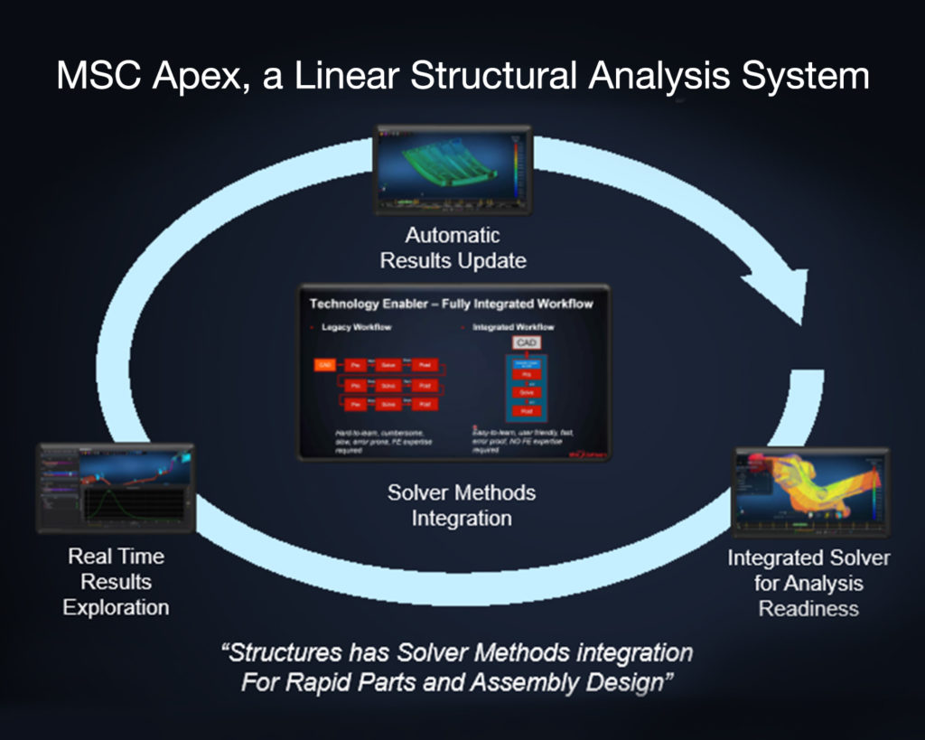
Siemens introduces Catchbook software, a new drawing and tracing app for tablets and smartphones that converts freehand drawings into accurate 2D designs. The new app provides a simple and intuitive user interface that works with both touch and stylus enabled Android, iOS and Windows operating system devices. Catchbook was designed to be a digital version of the proverbial napkin sketch, the birthplace of many amazing inventions – and even more home remodeling projects. Catchbook can be used to simply sketch ideas, just as one would do using pencil and paper, yet it’s smart enough to create precise, to-scale drawings that can be used for planning and construction. Even better, the drawings are completely editable via simple push and pull, making Catchbook far more powerful than any piece of paper. Developed by Siemens’ product lifecycle management (PLM) software business,

Catchbook was designed to be a digital version of the proverbial napkin sketch, the birthplace of many amazing inventions – and even more home remodeling projects. Catchbook can be used to simply sketch ideas, just as one would do using pencil and paper, yet it’s smart enough to create precise, to-scale drawings that can be used for planning and construction. The drawings are completely editable through push and pull, making Catchbook more powerful. Developed by Siemens’ product lifecycle management (PLM) software business, Catchbook is built on the company’s industrial sketching technology.

Catchbook gives users the ability to draw freely, or import an image or photograph and sketch over it to add details. Users rarely have to activate a menu or command. Instead, everything focuses on direct interaction with a finger or stylus. While there are many apps on the market that facilitate artistic visual representations, Catchbook is the only app that converts freehand sketching into mathematical curves representing precise drawings. Catchbook combines the simplicity of freehand sketching with the power of computer-aided design (CAD). It helps users create accurate CAD-compatible representations of their ideas.

Beneath its intuitive user interface, Catchbook employs some of the same technology used in most of the world’s leading CAD applications. Siemens’ D-Cubed software component works behind the scenes as a 2D geometric constraint solving tool to capture and preserve relationships between geometry. This is what enables users to interactively manipulate Catchbook drawings. These drawings can be shared directly via social media or email, or exported as images. Users can also directly export drawings as a sketch to virtually any graphic design or commercial CAD system including, Siemens’ NX software and Solid Edge software.
For information on Catchbook, please visit www.catchbook.com.

Siemens PLM Software, a business unit of the Siemens Digital Factory Division, is a leading global provider of product lifecycle management (PLM) and manufacturing operations management (MOM) software, systems and services with over 15 million licensed seats and more than 140,000 customers worldwide. Headquartered in Plano, Texas, Siemens PLM Software works collaboratively with its customers to provide industry software solutions that help companies everywhere achieve a sustainable competitive advantage by making real the innovations that matter.

Siemens
www.siemens.com/plm

Filed Under: Siemens PLM Tagged With: Siemens

Design space exploration: Adoption drivers, adoption constraints, potential adoption accelerators

April 7, 2016 By Mike Santora Leave a Comment

By Bruce Jenkins, President, Ora Research

Design space exploration today is enjoying ever-increasing levels of recognition, adoption and successful application to help solve some the world’s most difficult engineering problems. Nevertheless, there remain significant impediments to the even broader deployment and usage that champions of these tools and methods believe will be possible, and indeed imperative, to meet the product development challenges of the near future.

3DCAD-graphic-Ora_DSE_stack_REVISED-5-5-16

Design space exploration encompasses a family of applications and methods that include design of experiments (DOE), multidisciplinary optimization (MDO), multi-objective (Pareto) optimization, stochastic (robustness and reliability) optimization, and the rich family of structural optimization methods – shape, size, topology, topometry, topography and more. Supported by capabilities for multi-tool integration and simulation process automation, design space exploration is rooted in the domain originally termed “process integration and design optimization,” or PIDO.

What’s new? Why now?

Many of the methods that underpin design space exploration have been long known – and sometimes applied, in cases where the attendant costs in expertise, time and labor could be justified. What’s changing now is the way that fresh software technologies are transforming these powerful but formerly difficult-to-use methods into practical everyday engineering aids.

Why this matters is evident in the fundamental business justification for design space exploration: namely, the ability it confers on engineering teams and organizations to gain more complete, higher-fidelity visibility into product performance earlier in project schedules than was possible or practical with older technologies and approaches.

In essence, it does this by enabling more efficient, effective and revealing application of simulation, analysis and digital prototyping assets – tools, expertise, methods, work processes – to the perennial business drivers for any organization’s investments in those assets:

  • To become more competitive by gaining increased capability to explore, create and innovate.
  • To apply that capability to create better performing products.
  • To improve product quality and reliability – yielding expanded opportunity and customer appeal at the same time as lowered warranty expenses, liability exposure and lifecycle costs.
  • To control or, better yet, reduce product development schedules and budgets by supplanting costly, time-intensive physical testing with digital prototyping, and replacing intuition-based, guess-and-correct engineering practices with systematic, rational, rapid design discovery and evaluation.

New developments driving adoption and impact of design space exploration today

A number of key developments are driving and accelerating the adoption and impact of design space exploration today:

  • Advancing levels of built-in intelligence that let design exploration software choose the best search algorithms and solution methods autonomously, based on the user’s description of the problem in native engineering terms.
  • “Appification” of simulation – the embedment of design exploration and optimization technologies inside easy-to-use, product-specific and customer-specific simulation apps.
  • Full-cloud solutions that are beginning to expand accessibility, affordability and usability of design space exploration.
  • Continued vigorous marketing and sales activity by large CAE vendors that own premier design exploration technology.
  • Mounting pressures on engineering organizations to find new ways to do more with fixed resources, such as complying with the march of automotive CAFE and emissions mandates.

Legacy conditions constraining adoption and impact

Despite the foregoing advances, there remain a number of legacy conditions acting to substantially constrain and retard adoption and impact of design space exploration tools and methods at present:

  • Design exploration and optimization are still not part of the standard work process at enough engineering organizations.
  • The technology remains too often implemented at only the workgroup or department level, instead of as an enterprise competency.
  • Many small software developers offering highly capable technologies continue to struggle under marketing and sales resource constraints.
  • Some PLM vendors have yet to fully embrace design space exploration, fearing it a troublesome complication in an already complex CAE sales process.

Possible future developments that could spur interest and accelerate investment

Several developments possible in the near and intermediate future hold potential to spur interest and accelerate investment in design space exploration:

  • Market-development ripple effects from the growing democratization of topology optimization.
  • More acquisitions of design space exploration software developers by major CAE and/or PLM vendors.
  • New breakthrough technologies coming from startup developers, academic researchers or government R&D labs.

 Ora Research
oraresearch.com

Filed Under: Featured, News Tagged With: oraresearch

  • Go to page 1
  • Go to page 2
  • Go to Next Page »

Primary Sidebar

3D CAD NEWSLETTERS

MakePartsFast

Follow us on Twitter

Tweets by 3DCADWorld

Footer

3D CAD World logo

DESIGN WORLD NETWORK

Design World Online
The Robot Report
Coupling Tips
Motion Control Tips
Linear Motion Tips
Bearing Tips

3D CAD WORLD

  • Subscribe to our newsletter
  • Advertise with us
  • Contact us
Follow us on Twitter Add us on Facebook Add us on LinkedIn Add us on Instagram Add us on YouTube

3D CAD World - Copyright © 2021 · WTWH Media LLC and its licensors. All rights reserved.
The material on this site may not be reproduced, distributed, transmitted, cached or otherwise used, except with the prior written permission of WTWH Media.

Privacy Policy