• Skip to primary navigation
  • Skip to main content
  • Skip to primary sidebar
  • Skip to footer

3D CAD World

Over 50,000 3D CAD Tips & Tutorials. 3D CAD News by applications and CAD industry news.

  • 3D CAD Package Tips
    • Alibre
    • Autodesk
    • Catia
    • Creo
    • Inventor
    • Onshape
    • Pro/Engineer
    • Siemens PLM
    • SolidWorks
    • SpaceClaim
  • CAD Hardware
  • CAD Industry News
    • Company News
      • Autodesk News
      • Catia News & Events
      • PTC News
      • Siemens PLM & Events
      • SolidWorks News & Events
      • SpaceClaim News
    • Rapid Prototyping
    • Simulation Software
  • Prototype Parts
  • User Forums
    • MCAD Central
    • 3D CAD Forums
    • Engineering Exchange
  • CAD Resources
    • 3D CAD Models
  • Videos

Siemens Blogs

Siemens PLM advances systems-driven product development with LMS Imagine.Lab 14

May 20, 2015 By Paul Heney Leave a Comment

By Bruce Jenkins, President, Ora Research LLC

lms_imaginelab_14aLMS Imagine.Lab 14, the latest release of Siemens PLM’s software for multi-domain system simulation, shows the company delivering on the vision it outlined when it acquired LMS International in 2012—“to provide a closed-loop systems-driven product development solution.”

Siemens PLM CEO Chuck Grindstaff said at the time, “Integrating the full environment gives our customers the ability to bring together information from the logical model, physical model and functional model to refine and optimize designs and measure results, which transforms decision making in product development.” What Grindstaff termed the “logical model” is what’s created and managed in LMS Imagine.Lab, which has three components:

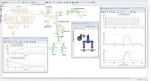
• LMS Imagine.Lab Amesim, an integrated simulation platform for multi-domain mechatronic systems simulation
• LMS Imagine.Lab Sysdm, a model and data management tool for model-based systems engineering
• LMS Imagine.Lab System Synthesis, which provides configuration management, system integration and system architecture management

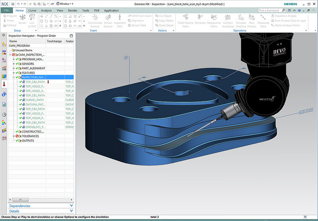
In the newest release, LMS Amesim capabilities have been extended to facilitate continuity between CAD and the 1D simulation approach, with CAD file import/export capabilities that let users extract geometric information to populate submodel parameters in LMS Amesim.

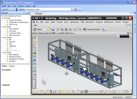
For LMS Sysdm, development efforts focused on integration of model management within the organizational environment. LMS Sysdm 14 provides a direct link from LMS Sysdm to Teamcenter, allowing system engineers to directly publish validated models to the Teamcenter repository while accounting for their daily activities. Thus, system simulation is now integrated under the umbrella of PLM, taking into account daily versioning and branching, which are mandatory for monitoring modeling activities.

Why does all this matter? In our ongoing research among engineering workgroup leads and discipline leads, we’ve long been struck by their frustration at the disconnects between the systems modeling and 0D/1D simulation tools at the heart of conceptual and preliminary engineering, and the higher-fidelity analysis tools used downstream—not to mention the hamstrung work processes and loss of visibility caused by the persisting disconnects between all those applications and the CAD systems that support detailed design. The “V” model of product development is all too apt today, in that decisions in the upper left of the V, once made—and the tools used to make them—are difficult to revisit and re-exercise once the project starts down the greased slope of the V.

Of course, much of this is due to the inherent nature of project trajectory, but discipline and program leads tell us that much could be gained from capabilities for more multi-fidelity and multi-directional workflows among all the tools across the product development lifecycle. Indeed, most report they have difficulty seeing how to advance from current-generation systems modeling tools and practices to the vision of true model-based systems engineering without the evolution of such capabilities.

Against that background, we’re encouraged to see Siemens PLM delivering on its vision of “closed loop systems-driven product development.” Its new LMS Imagine.Lab release will help engineering organizations make progress toward closing the loop between the systems modeling and 1D simulation tools where a project’s most crucial engineering decisions are made, and the remainder of the toolset chain in which those decisions are detailed and implemented.

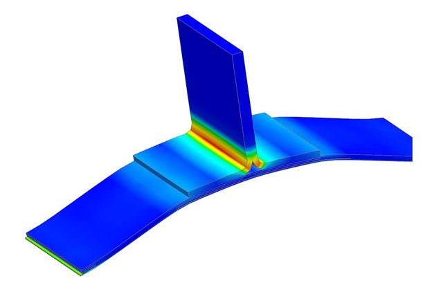
Notes: Systems modeling software consists of tools and languages for systems engineering: The specification, analysis, design, verification and validation of systems and systems-of-systems. In discrete manufacturing, systems engineering is the coordinated specification-through-validation of complex physical systems across multiple domains—mechanical, electrical, electronic, hydraulic, thermal, control, electric power, others. 0D/1D simulation uses the time dimension only (0D), or time plus a single spatial dimension (1D), to model and evaluate critical aspects of a system’s behavior. By contrast, 3D CAE takes account of a model’s behavior in all three spatial dimensions (or 2D for plate structures and other cases where the third dimension can safely be neglected). Together, systems modeling and 0D/1D simulation are used early in engineering programs to make a product’s essential functional and architectural decisions.

Filed Under: CAD Blogs, Siemens Blogs, Siemens PLM

Siemens Rolls out Tecnomatix 12

November 21, 2014 By Barb Schmitz Leave a Comment

Factories today hardly resemble the factories of yesteryear. Today’s factories are full of high-tech digital machinery and robotics that are highly automated. To make today’s digital factories run more efficiency, manufacturing software also needs to advanced.

Siemens this week released the newest version of Tecnomatix software for digital manufacturing, which the company says will help companies in a wide range of industries innovate better and at less risk.

Let’s take a look at what’s new in Tecnomatix 12:

Easy Plan. This new web-based app for plant-specific production planning provides the ability to analyze ‘what-if’ scenarios to ensure feasibility of assembly processes within performance targets. Also assists in identifying value-added and nonvalue-added tasks for the purpose of achieving maximum assembly efficiency.

It works by enabling production planners to link the product design and manufacturing requirements to create detailed plant-specific process plans. Manufacturing operations are defined with 3D visual work instructions, balanced for the available resources and analyzed for cycle times. The software app is intended to be used by factory-floor production planners that need to stay ahead of fluctuating production forecasts and numerous product configurations; while staying within the necessary Takt time.

Advanced robot programming. New simulation solutions for dual arm and cooperative robots can automate more manual tasks, improve efficiency and quality. Robotics programming and simulation is a proven technology for programming and synchronizing multiple independent robots and devices that work together. Tecnomatix 12 introduces new capabilities to program the latest dual arm and cooperative robots that are controlled as one.

Siemens Tecnomatix 12's robot programming simulation solution for dual arm and cooperative robots can automate more manual tasks, improve efficiency and quality.
Siemens Tecnomatix 12’s robot programming simulation solution for dual arm and cooperative robots can automate more manual tasks, improve efficiency and quality.

It was developed for manufacturers that need to automate manual tasks performed by human beings in order to compete on price and quality – such as those that assemble high-tech electronics and perform packaging. Newly available robots can perform tasks once only workable by humans – and are able to safely work alongside production personnel. While these robots are starting to replace real people in factories, they require skilled workers for programming, installation and maintenance which will create new and higher paying jobs.

Plant Simulation. Optimize complex manufacturing systems for more industries with more productivity. Users build smart digital models of their discrete manufacturing systems in a state-of-the-art 3D simulation environment and then run experiments to identify which processes, parameters and settings result in the best performance. With Tecnomatix 12 the user experience is modernized and new capabilities are available to model and simulate continuous processes that utilize fluids and recipes.

This app was developed for manufacturers that need to achieve efficiency targets, and reduce operating expenses and capital investments. Plant Simulation can assist in identifying opportunities to boost production efficiency and throughput, and minimize energy usage as well as the negative effects that manufacturing can have on the environment. It is proven to reduce capital investments, eliminate bottlenecks, reduce WIP (work in progress) inventory, minimize emissions and reduce energy utilization.

PLM-MES solution enhancements. Close the loop between the virtual and real worlds of production with a model-based execution environment. In the product lifecycle management (PLM) environment, design intent defined on 3D models in the form of product manufacturing information (PMI) is linked to the manufacturing process and delivered directly to the manufacturing execution system for validation in production. Shop floor operators capture non-conformances in the system for disposition and tracking, and corrective and preventive actions are initiated and managed.

PLM-MES integration helps companies execute more efficiently and with more agility. It closes the loop between manufacturing and design by managing change, improving visibility, hard-wiring compliance, and increasing design for manufacturability potential.

Big Data solution for production quality. Take control of production by using volumes of measured data to identify and react to quality trends. Dimensional quality data collected from connected measurement devices in production is loaded into a database where smart analytic tools are used to automate data reporting and generate executive dashboard reports. Enhanced tools are available to help engineers visualize, identify and react to quality trends, as well as correct and prevent issues from recurring. This solution is scalable: it can monitor quality data for multiple devices, factories and even suppliers.

You can find additional information about about the new features of Tecnomatix 12 here.

Barb Schmitz

Filed Under: CAM, News, Siemens Blogs, Simulation Software Tagged With: Siemens

Siemens Releases NX 10 Software

October 7, 2014 By Barb Schmitz Leave a Comment

The latest version of Siemens’ NX software has been released, touting among many things increased design flexibility and up to 3X higher productivity for users. New tools, such as the 2D concept development solution, make it easier and faster to create designs, while enhancements to NX Realize Shape software, a fully integrated sub-division modelling environment, provide designers with more flexibility to produce unique shapes.

A new optional touch-enabled interface provides expanded access to the full design capabilities of NX. And tighter integration to product lifecycle management (PLM) software–through Siemens’ Active Workspace environment–reduces the amount of time spent searching for product information. NX 10 also includes multiple enhancements throughout the integrated computer-aided design, manufacturing and engineering (CAD/CAM/CAE) solution.

These include:

2D concept development. Increasing product complexity makes 3D modeling the preferred method of product design throughout the world. However, in some industries including machinery and complex electronics, it is easier and faster to create initial design layouts in 2D. The new 2D concept development solution enables designers to explore concepts in 2D, making it up to three times faster to create new designs. Once the design is finalized it can easily be migrated to 3D to complete the model.

Enhancements to the NX Realize Shape. Enhanced solution give designers even more control over geometry modelling to produce products with highly stylized shapes or complex surfaces. NX Realize Shape is based on sub-division modelling, a mathematical approach to creating 3D geometry with smooth flowing shapes, pioneered by the entertainment industry. The tool is seamlessly integrated with NX which helps shorten product development time by eliminating the multiple steps associated with using separate tools for freeform design and engineering development.

Optional touch-enabled interface. This interface adds the flexibility of accessing NX on tablets running Microsoft’s Windows operating systems, making it easier to use NX when and where needed to enhance collaboration and productivity. Combining improved access to NX with tighter PLM integration through Active Workspace, the innovative interface to Siemens’ Teamcenter software, enables users to quickly find relevant information, even from multiple external data sources. Active Workspace can be accessed via the web on any device from any location.

NX Laminate Composites supports the new NX CAE environment for the LMS Samcef Solver, to create cohesive layers between extruded plies to model delamination.

Enhanced multiphysics capabilities. Significantly enhances simulation integration by connecting two or more solvers to streamline the process of performing complex simulations. The multiphysics environment delivers a consistent look and feel for performing multiphysics simulations so engineers can easily build coupled solutions on the same mesh using common element types, properties, boundary conditions, and solver controls and options.

Industry-specific capabilities in NX CAM. Helps engineers program faster and machine higher quality parts. New dynamically-adjusted roughing strategies automatically adapt to part geometry to enable better mold and die machining. New automated inspection programming capabilities in NX CMM (coordinate-measuring machines) enable the use of PMI (Product Manufacturing Information) to create inspection scanning paths. This helps significantly speed up the inspection process compared to the currently available touch point method.

Scanning inspection paths can be automatically created with NX CMM by using the embedded PMI data.

Production line design. NX 10 also includes new production line design capabilities for automotive assembly manufacturing. The new line designer application enables engineers to design and visualize layouts of production lines in NX, and use Teamcenter and Siemens’ Tecnomatix software to manage the designs, and validate and optimize manufacturing processes.

NX 10 will be available in December. For more detailed information on all the new functionality in NX 10, please visit here.

Barb Schmitz

Filed Under: News, Siemens Blogs, Siemens PLM Tagged With: Siemens PLM

Siemens Forms Partnership to Help Customers Automate Engineer-to-Order Processes

June 27, 2014 By Barb Schmitz Leave a Comment

Manufacturers are under the gun increasingly today to develop more customized products for customers. Also referred to as “mass customization,” creating products with specific functionality for special niches of customers is at odds with traditional mass production methods that have been in place for years. In order to respond, companies must adapt and change both their internal design processes as well as the way in which they manufacture products.

Siemens and Tata Consultancy Services, a leading IT services and consulting company, have joined forces to create a new joint software and services solution for automating complex Engineer-to-Order (ETO) processes. The solution will be called ETO2Win and it leverages TCS’s domain expertise and Siemens’ Rulestream software.

ETO2Win is designed to capture, manage and reuse corporate intellectual property to automate engineering processes for manufacturers. ETO2Win addresses business challenges faced by ETO manufacturers by streamlining business processes associated with custom-built products, improving proposal accuracy and win rates, and enhancing the predictability of costs, margins and on-time delivery.

Siemens forms an alliance with TCS, an IT consultancy, to create a joint solution for Engineer-to-Order processes.

“Siemens’ powerful ETO software technology, combined with TCS’ proven ETO process framework, provides our customers with an enterprise-level solution for accelerating sales and order engineering processes for custom products,” said Caroll Jarvis, vice president, Global Alliance Sales, Siemens PLM Software. “This innovative software and services approach has created a comprehensive solution that reduces implementation time and risk, ultimately yielding a faster return on our customers’ PLM investment and helping to improve the bottom-line.”

A large and growing number of manufacturing industry segments, including power generation, HVAC (heating, ventilation, and air conditioning), fluid flow technologies, heavy equipment, machinery, and the automotive and aerospace supply base employ ETO business processes.

The increasing demand for customized or customer-specific product configurations creates a common set of challenges for these companies. There is constant competitive pressure for ETO manufacturers to increase the number, accuracy and win rate of their bids, while reducing order engineering lead time and optimizing resource utilization in manufacturing.

Rulestream addresses the unique challenges faced by ETO manufacturers with a comprehensive solution spanning sales, engineering and manufacturing. By capturing engineering knowledge and using it to automate key business processes across the enterprise, ETO2Win, with Rulestream and TCS’ ETO process framework and best practices, streamlines the inquiry-to-quote and order-to-release processes for even the most complex products, enabling manufacturers to sell according to their engineering and manufacturing capabilities.

To find out more on the Siemens PLM Software and TCS alliance, click here.

Barb Schmitz

Filed Under: News, Siemens Blogs Tagged With: engineer-to-order, manufacturing, Siemens

Siemens NX Helps University Design Better Soccer Players

June 23, 2014 By Barb Schmitz Leave a Comment

With all the excitement at full tilt with the 2014 FIFA World Cup underway in Brazil, the whole world seems to have gone soccer-crazy, with many people hitting local fields to practice their own ball-handling skills. At Graz University of Technology in Austria, that includes robots. The university is designing and building robots to be superior “soccer players.”

No water bottles required

Propelled by omnidirectional roller drives, the robots are fully autonomous and carry everything on board, from the power supply to the compressed air bottle for the kicking mechanism. The only input from the outside are the referee’s commands.

The need for well-defined, easy-to-communicate rules is critical for testing the efficacy of autonomous robots from an artificial intelligence perspective. Most of all, the test environment must provide changeable conditions that closely mirror reality. The game of soccer fulfills these conditions.

Battling for victory in the RoboCup

The RoboCup competition was established in the 1990s as a test bed for research, development and university education. Matches strictly follow FIFA rules and are played in various categories. Playing soccer, however, is not the point. The goal is to design methods for autonomous robots that can quickly make correct decisions based on their observations.

Propelled by omnidirectional roller drives, the robots are fully autonomous and carry everything on board, from the power supply to the compressed air bottle for the kicking mechanism.

For now, robots play against robots in these tournaments. However, a challenge has already been announced: In 2050, a team of robots is scheduled to play the human team holding the World Cup at the time. One team from the university has been participating in the world championship since 2003.

Tackling a new robot design required the team to improve their mechanical design process. “The older robot generations were created with a mix of 3D CAD modeling and hand drawings,” says Norbert Rath, head of mechanical engineering within the group. “This involved using a CAD system that is particularly unwieldy and forces users to employ strictly parametric methods.”

Searching for a better design tool

The CAD tool the team used in the past also had certain shortcomings in drawing conversion. Due to high application complexity, work could not commence without an enormous amount of training and familiarization.

With frequent staff changes, the team searched for an alternative that would provide high-functional capabilities, while being easy to learn with minimal training requirements, along with the ability to distribute work so that multiple team members could contribute to the overall task without requiring significant coordination efforts.

Researchers at Graz University of Technology in Austria are using Siemens NX software to design robots to be superior soccer players.

As a result, in early in 2009, the RoboCup team licensed NX software from Siemens PLM Software. Adopting the use of NX, Graz University of Technology students reported significant benefits, which included: reduced data preparation work from a week to a day; improved data efficacy; facilitated collaboration between team members; reduced number of physical prototypes; and optimized budget and resources.

To learn more about Siemens NX software, click here.

Barb Schmitz

Filed Under: News, Siemens Blogs, Siemens PLM Tagged With: artificial intelligence, cad, NX

Siemens Introduces Solid Edge ST7

May 15, 2014 By Barb Schmitz

Amid the palpable excitement of its most ardent users, Siemens introduced the latest release of its flagship software, Solid Edge ST7 at this year’s Solid Edge University in Atlanta, Georgia. It’s no wonder the crowd of users was excited; this new release is packed with a staggering 1,300 user-requested enhancements.

The goal of the new release, according to Karsten Newbury, senior VP and general manager of the company’s Mainstream Engineering Software, was to improve the productivity and efficiency of the product design process. “At Siemens we develop software for our users,” says Newbury. “Solid Edge ST7 significantly elevates the user experience; its new enhancements help ensure a much faster, easier learning curve for new users and improved efficiency for experienced ones. This makes our exclusive synchronous technology even more accessible to everybody.”

What’s new?

Sounds good, but time to dig down and take a look at some of the new functionality included in ST7.

Photorealistic rendering. In the April issue of Design World, I wrote a feature on the growing importance of rendering to the product development process. ST7 now offers built-in rendering, courtesy of Luxion’s KeyShot technology, that enable users to quickly and easily create photorealistic images and animations from within the modeling environment, significantly improving the overall image quality and speeding real-time photorealistic rendering of native 3D models by up to five times, based on internal testing.

Solid Edge ST7 now includes built-in rendering courtesy of Luxion's KeyShot technology.
Solid Edge ST7 now include built-in rendering courtesy of Luxion’s KeyShot technology.

3D Sketching. This new functionality, which is available in the part, assembly and sheet metal environments, improves efficiency with various modeling scenarios, allowing designers to complete their design processes up to two times faster with greater flexibility. 3D Sketch can also be used to model pipes and wires that are bent in more than one plane, and in the assembly environment for the definition of exact paths for piping, wiring and tubing.

Improved UI. Enhanced user interface features a new start page, focused learning paths, and expanded visual tool tips that all simplify the learning curve for new users and increase efficiency for expert users. Startup page provides easier access to templates, recent documents, instructional videos, and the online community and standard parts.

Visual data management. Design management capabilities, based on Microsoft’s SharePoint software, provide a more visual design management approach with a new workflow site that brings user interactions into one location. This makes it easier to create and work with complex design projects, complete engineering changes faster and improve overall productivity.

Faster assembly design. The Duplicate Component command speeds assembly design in which components are duplicated in many positions and orientations. Multiple copies of a component can be created based on designated “from” and “to” positions and orientations of existing components.

Create a blank from a 3D model. Rapid creation of manufacturing information for components that are manufactured using forming, stamping and deep drawn manufacturing processes is now possible using the “Create Blank” command that enables users to create a flattened blank for any 3D model.

More apps. New Solid Edge apps provide wider capabilities for design, manufacturing and collaboration that speed the entire product development process. New apps include those that provide mobile access to standard and catalog parts; automated output of models for 3D printing; expanded manufacturing capabilities; and cloud-based collaboration. There are now over 500 Solid Edge apps available in the company’s app store.

We’re barely scratched the surface on all the enhancements packed into Solid Edge ST7, so check out this page on the Siemens PLM Software’s web site for more.

Filed Under: 3D CAD Package Tips, CAD Package, News, Siemens Blogs, Siemens PLM Tagged With: Solid Edge

Geometric Ships CAMWorks 2014 for Solid Edge

May 9, 2014 By Barb Schmitz Leave a Comment

Innovation is today’s CAD products is somewhat expected by users who constantly demand the next level of functionality. After all, designers and engineers are using modern CAD tools to design the next great product, or at least the next great version of a product. The same cannot necessarily be said on the CAM side, where progress to innovate tools has been slower.

As the costs of modern machining technology has dropped and become more accessible, more and more designers and engineers tasked with outsourcing prototyping or doing it in-house are getting more involved with the CAM side of the equation. They are also interfacing more frequently with the manufacturing personnel running CNC machines.

Crossing the CAD-CAM Divide

There’s traditionally been a bit of a divide between engineering and manufacturing, possibly a result of the fact that they “talk” different languages in that they use disparate systems. The format created by CAD programs doesn’t seamlessly transfer to the CAM program and engineers are often accused of “lobbing” models over to manufacturing for them to deal with.

To alleviate some of these issues, CAD-integrated CAM packages began to emerge. The goal was to create a CAD-like workflow for CAM so engineers and designers would not have to learn a whole new software system.

Yesterday, Geometric Ltd. announced the shipment of CAMWorks for Solid Edge users. The new version provides even tighter integration with Solid Edge, Siemens PLM Software’s 3D CAD software, to speed programming time and accelerate time-to-market.

CAMWorks is an embedded CAM program that is fully integrated with Solid Edge.

One of the software’s users, Tim Hoeing, a plant manager at H&M Tool & Die, is a big fan of the software’s feature-based approach. “The feature-based approach seems much more intuitive than the process of creating profiles and chains method,” says Hoeing. “The automatic feature recognition and tool path associativity helps reduce programming time by as much as ten times. And the knowledge-based machining will save machining strategies for future use, enabling faster turn-around times on new jobs.”

With this release, Solid Edge users will gain access to the full suite of CAMWorks modules, including Sync Manager and Sub Spindle operations manager to speed up CNC programming for complex multi-spindle, multi-turret mill turn machines.

In addition, with the 5-axis simultaneous machining module, users in the aerospace, medical device, and oil & gas industry have the ability to machine complex surfaces using advanced 4- and 5-axis machining centers. Furthermore, tool and die customers now have the ability to program the Wire EDM machines within the same environment as their milling operations instead of having to maintain different software for different purposes.

CAMWorks 2014 also adds new mill-turn capabilities along with 5-axis simultaneous machining and assembly-mode machining, enabling users to confidently and accurately create tool paths that avoid fixtures, clamps, and other necessary work-holding devices, which is essential for today’s complex machining centers.

For more on CAMWorks 2014, check out this page on the Geometric Ltd web site.

Barb Schmitz

Filed Under: CAM, News, Siemens Blogs, Siemens PLM Tagged With: cam, Siemens, Solid Edge

Siemens Offers NX Nastran FEA Software in the Cloud

May 7, 2014 By Barb Schmitz Leave a Comment

Many engineering software providers are porting their software to the cloud as an option for users. Benefits of cloud deployments of engineering software include lower costs, faster deployment, lower maintenance costs and increased scalability.

Simulation software, in particular, benefits from being implemented through the cloud. Simulation software has been traditionally very expensive and requires significant hardware horsepower to run effectively, especially when simulating large models.

Cloud implementations offer users a way to cost-effectively run simulations to evaluate more design options in order to improve efficiency and product quality and speed time to market.

Siemens moves FEA to the cloud

Siemens has partnered with Rescale, a leading cloud simulation platform provider, to enable their customers to customize simulation compute capacity, based on their individual requirements, to perform virtual product simulations. Using Rescale’s on-demand, dynamically scalable cloud environment, NX Nastran users can run hundreds of simulations simultaneously, leveraging a pay-per-use operating expense model.

Siemens is hoping that this more cost-effective option will enable new customers to quickly gain the benefits of Nastran without the high initial costs of deployment, while existing customers can maintain their in-house analysis capability for ongoing activities and ramp up using the Rescale simulation platform on an hourly basis for peak demand.

Engineers can perform complex simulations, such as noise, vibration and harshness (NVH) analysis, via the cloud using NX Nastran.

Cloud platform makes DoE simulations more cost-effective

Rescale’s simulation platform seamlessly integrates simulation software with a customizable HPC infrastructure, helping engineers and scientists develop more innovative products by performing research and development much faster. Rescale offers users numerous workflow options including executing one job at a time, running multiple jobs in parallel, and performing designs of experiment (DoE) simulations that execute hundreds of individual runs for varying parameters across the design space.

Engineers run DoE simulations to better understand the effects of parameter variations on the robustness of their designs or to evaluate a broader design solution space. The new on-demand platform makes large DoE simulations significantly more affordable and practical due to a volume pricing model that provides higher discounts with an increasing number of runs.

Find out more on NX Nastran in the cloud here.

Barb Schmitz

Filed Under: CAE, News, Siemens Blogs, Siemens PLM Tagged With: FEA, Siemens NX

The Role of Associativity in Direct Modeling

April 1, 2014 By Barb Schmitz Leave a Comment

When designers and engineers think about design associativity, they often think about history-based 3D modeling systems. CAD software that deploys a history-based approach to modeling requires engineers to anticipate and define feature constraints, relations and dependencies, which ensures that any design change will update all related downstream geometry. That’s design associativity.

Though they require a lot more work, thought and pre-planning on the part of the user, history-based modeling systems provide users with a methodical, orderly and powerfully automated way to create models. The problems arise, however, when changes have to be made, a rather common occurrence at all stages of development. Even small design changes cause a domino effect so users must carefully consider the impact a change will have to associated parts.

Design associativity is not exclusive to history-based 3D modeling approaches. Image courtesy of PTC.

Is there associativity in direct modeling?

During The Pros and Cons of 3D Modeling Paradigms webinar, one of the questions asked of our panel of experts was what is the role or definition of associativity in direct modeling? Our panelists each brought a unique perspective to that question, which I thought was worthy of sharing.

Dan Staples, vice president of Solid Edge Product Development, Siemens PLM Software

To me the word associativity with parametrics is the notion that changing one thing changes other things that are associative. Things can be related to one another and things can be dimensionally driven and, therefore, association between the dimension and the faces. The key difference is that it doesn’t cause a linear regeneration of the treetop to bottom. That expensive piece is you edit the first feature and you pay for all subsequent thousand features.

That’s not true in a direct modeling system. However, there is the notion of associativity, meaning that things can happen. Dimensions are edited and faces moved, or Face A is associated with Face B and, therefore, it should move also. That’s associativity by my definition, and it’s perfectly valid in a direct modeling system.

Chad Jackson, principal analyst, Lifecycle Insights

There is probably a finer point here, which is there’s design associativity and there’s deliverable associativity. You might want to have design intent because of intent ripple has a change ripple across multiple parts in the same assembly. You might want to have that. Obviously when you change a part, you want the drawing to update and you want a service assembly animation to update. I think in both of those cases, neither are really limited by direct modeling. I think they are separable.

Brian Thompson, vice president, Creo Product Management, PTC

Maybe another way to look at is when you’re building in a history-based parametric modeling system, every selection that you make of some other geometry to create a dimension or to lay it on the line in a sketch or whatever it may be, it does create a dis-associativity that you as an engineer you have to consider: is that an important thing? Is that aspect important to my design intent? If it is, that can be a very powerful thing and they’re inherent in the design process.

Whereas with direct modeling, I would say that kind of thing is very much put in right at the top of mind of the engineer as they’re working through the direct modeling process. They will put that in into the design as they see fit. It’s something that the design engineer consciously decides; I want to create dis-associativity. It just doesn’t happen as a natural part of the design process, whereas in history-based systems, it very much is ingrained. Selections that you make do in fact create associative references unless you specifically say no I don’t want that. It’s usually the opposite assumption in direct modeling.

If you missed “The Pros and Cons of 3D Modeling Paradigms” webinar, you can still see it here.

Barb Schmitz

Filed Under: 3D CAD Package Tips, Creo, News, PTC/CoCreate Blogs, Siemens Blogs, Siemens PLM Tagged With: design associativity, Direct Modeling, PTC, Siemens

7 New Year’s Resolutions for CAD Users

December 30, 2013 By Barb Schmitz Leave a Comment

As we approach year’s end and begin looking towards a brand-spanking new year, many of us will make New Year’s resolutions. These are often health-related (eat less, exercise more, drop a few pounds, quit an unhealthy habit or two) or family-related (yell at my kids less, be more considerate of my significant other, walk the dog more, etc.). Why not make a few work-related resolutions this year?

All engineers should occasionally take stock in where their career is at and the things they can do to advance it forward, whether at their current employer or to greener grasses elsewhere. So with this mantra in mind, I’ve decided to toss out a few New Year’s Resolutions to consider based on trends I’ve seen over the past year. Embrace them all, adapt a few, or ignore completely; it’s really your call. Or add a few of your own in the comment section.

Without further ado, here’s my list:

  1. Learn the basics of simulation. You’re a bonafide pro at your CAD system, but more and more companies are moving towards adapting simulation (FEA and CFD) into product development to lower prototyping costs and speed development. Take the initiative and sign up for an e-learning course online. NAFEMS offers code-independent classes that offer introductions to FEA and Fluid Mechanics, among many others. Check out the schedule and course titles here.
  2. Lobby for faster computers. One way to achieve an instant uptick in productivity is to rev up your computing power. Because of the booming popularity of tablets, the prices of PCs have plummeted. Their loss is your gain. Time to get your manager on board with a hardware upgrade. A four-core, Xeon-based PC with 16 GB of RAM and blistering-speed graphics will cost you less than $3K.  Spend $2K more and you’ll score an eight-core PC with 32 GB of RAM, solid-state disks and high-end graphics processing.

    High-end engineering workstations, such as this HP Z Workstation, are now super affordable, making this a great time to upgrade.
    High-end engineering workstations, such as this HP Z Workstation, are now super affordable, making this a great time to upgrade.
  3. Check out subscription-based CAD. If your company’s business is cyclical in nature (i.e. you only need CAD on a project basis), you might want to look into purchasing CAD, as well as add-on software, on a subscription basis. Several of the larger CAD vendors are now offering CAD tools on a monthly subscription basis, enabling smaller companies to move CAD from a capital expense to an operating expense. Siemens is now offering users access to full-fledged Solid Edge CAD software for a monthly subscription prices starting at $130. Give it a free 45-day test drive here.
  4. Become a better public speaker. Do you have ambitions of one day becoming a CAD or engineering manager? If so, keep in mind that managers must not only engage with staff engineers but also with executive management, customers, suppliers and outside agencies. Being comfortable speaking in front of others is not a talent all of us are born with so taking the time to develop these “soft” skills is important. Toastmasters International, a non-profit organization, is a great place to get your feet wet in public speaking.

  5. Investigate the cloud. Perhaps your company has avoided moving to the cloud for fear of IP security. Take the lead and look into the possible advantages the cloud could offer your company. Autodesk was the first to put CAD in the cloud with its Fusion 360 product, which offers excellent and easy-to-use data management tools and takes advantage of unlimited computing resources via the cloud. Autodesk also debuted the industry’s first CAM tool in the cloud, CAM 360, at this year’s Autodesk University. The company also offers SIM 360, simulation software in the cloud.

    Autodesk offers a cloud-based simulation tool, SIM 360, enables users to do mechanical FEA simulations anywhere at a fraction of the normal cost.
    Autodesk offers a cloud-based simulation tool, SIM 360, which enables users to do mechanical FEA simulations anywhere at a fraction of the normal cost.
  6. Try a new 3D modeling tool. There has been much debate in the CAD industry about which 3D modeling paradigm is best. Parametric modeling offers engineers a powerfully automated way of creating complex models, especially large assemblies that use families of parts. Direct modeling tools are easier to learn and use, changes are made through intuitive push-pull interactions and are ideal for concept development and collaboration. Might be a good time to try and learn both, as the either-or proposition seems to be ending. Mark your calendar: industry analyst Chad Jackson and leading experts from the CAD companies will be debating this topic in an upcoming Design World webinar on February 20th.
  7. Think like a businessman. Yes, I know you went to college to study engineering, not business, but companies more and more and looking for engineers who are business-savvy and innovative thinkers. They want engineers who have been involved with strategy and planning and know their way around a balance sheet. If you want to advance, you need to understand how the total costs to produce your company’s products affects bottom-line business decisions.

Barb Schmitz

Filed Under: Autodesk News, CAD Package, CAE, CFD, Company News, News, Siemens Blogs, Siemens PLM, Siemens PLM & Events Tagged With: Autodesk, cad software, Siemens PLM, simulation

  • Go to page 1
  • Go to page 2
  • Go to Next Page »

Primary Sidebar

3D CAD NEWSLETTERS

MakePartsFast

Follow us on Twitter

Tweets by 3DCADWorld

Footer

3D CAD World logo

DESIGN WORLD NETWORK

Design World Online
The Robot Report
Coupling Tips
Motion Control Tips
Linear Motion Tips
Bearing Tips

3D CAD WORLD

  • Subscribe to our newsletter
  • Advertise with us
  • Contact us
Follow us on Twitter Add us on Facebook Add us on LinkedIn Add us on Instagram Add us on YouTube

3D CAD World - Copyright © 2021 · WTWH Media LLC and its licensors. All rights reserved.
The material on this site may not be reproduced, distributed, transmitted, cached or otherwise used, except with the prior written permission of WTWH Media.

Privacy Policy