• Skip to primary navigation
  • Skip to main content
  • Skip to primary sidebar
  • Skip to footer

3D CAD World

Over 50,000 3D CAD Tips & Tutorials. 3D CAD News by applications and CAD industry news.

  • 3D CAD Package Tips
    • Alibre
    • Autodesk
    • Catia
    • Creo
    • Inventor
    • Onshape
    • Pro/Engineer
    • Siemens PLM
    • SolidWorks
    • SpaceClaim
  • CAD Hardware
  • CAD Industry News
    • Company News
      • Autodesk News
      • Catia News & Events
      • PTC News
      • Siemens PLM & Events
      • SolidWorks News & Events
      • SpaceClaim News
    • Rapid Prototyping
    • Simulation Software
  • Prototype Parts
  • User Forums
    • MCAD Central
    • 3D CAD Forums
    • Engineering Exchange
  • CAD Resources
    • 3D CAD Models
  • Videos

General Blogs

CATIA V5: How to control video file size

March 15, 2021 By WTWH Editor Leave a Comment

By Iouri Apanovitch, Senior Technical Training Engineer, Rand 3D

The built-in CATIA video recorder is an essential tool when working with animations in kinematics, fitting simulator, human modeling, etc. When the default video settings are used, however, the resulting video files are quite large, making them difficult to share through a company.

Here’s how to control the video file size in CATIA V5.

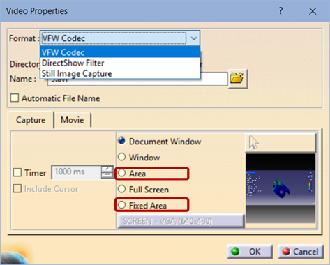
Before starting the recording, select (Setup) icon to open the Video Properties dialog box, at the top of which you will see the Format pull-down list.


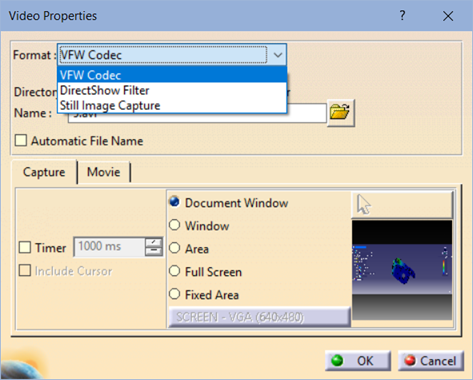
The default VFW Codec option records the video in an uncompressed AVI file. It provides the best video quality, at the cost of a very large file size. A one-minute-long video can be as large as 2Gb or more.

The DirectShow option lets you create smaller, MPEG-compressed files. Select the Movie tab and click Compressor Setup button to open the compression options.


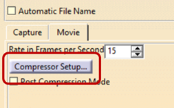
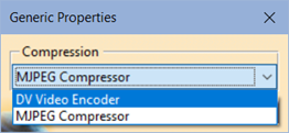
If you don’t see the two compression options shown above (DV Video Encoder and MJPEG Compressor), it means that you need to install the codecs. To do that, run the file 3DSMJPEGVFWSetup.exe located in the \code\bin sub-folder of the CATIA install directory.

Using either of the two codecs creates smaller files, of course at the cost of quality. The MJPEG Compressor results in the smallest files.

You can also use the Rate in Frames per Second (FPS) setting to further reduce the file size. However, be aware the very low FPS rate may result in your video appearing ‘jerky.’

Lastly, you can use either Area or Fixed Area options to limit the captured area and to reduce the file size even further.

The final recommendation – test the settings by yourself on a sample recording, to make sure you hit the right balance between the video quality and the file size.

About the Author

Iouri’s primary area of expertise is product analysis and simulation with FEA tools such as SIMULIA/Abaqus, Autodesk Simulation, Mechanica, including linear and non-linear simulations, dynamics, fatigue, and analysis of laminated composites.


Filed Under: General Blogs Tagged With: rand3d

Avoiding singularities in FEA boundary conditions

February 26, 2021 By Leslie Langnau Leave a Comment

FEA boundaries can usually be obtained using simple fixed constraints. But, this can result in singularities that produce erroneous results. To determine whether results show a real stress concentration or a singularity, an accurate solution can usually be obtained by either using elastic supports or modeling contact between components.

Singularities caused by sudden changes in boundary conditions can be harder to spot and resolve. In fact, setting up realistic boundary conditions is often the most challenging aspect of a simulation.

Dr. Jody Muelaner, PhD CEng MIMechE

Singularities in Finite Element Analysis (FEA) can cause real issues, even for an apparently simple structural analysis. Singularities lead to completely erroneous results and stresses that continue to rise as a mesh is refined. Many singularities are caused by stress-raising geometry such as holes and sharp internal corners, and this is generally well understood. Singularities caused by sudden changes in boundary conditions can be harder to spot and resolve. In fact, setting up realistic boundary conditions is often the most challenging aspect of a simulation.

What is a singularity?
A singularity is a point in the model where a value, such as stress, tends to infinity. As the mesh is refined, the increasingly small elements get closer to this point and the value therefore rises. As the element size tends to zero, the stress will tend to infinity. This produces nonsensical results and prevents mesh convergence.

Geometry that causes singularities
Singularities caused by stress-raising geometry such as holes and sharp internal corners are well understood. In the real world, there is likely to be a small radius on any internal corner, meaning the stress would not actually continue to rise. In any case, local yielding will limit the stress in such features. The location of these singularities can often be readily identified, excluded from convergence results and localized models used to predict the true stress in the features responsible. Singularities at corners are similar to cracks and the stress intensity factor can be calculated using the J-Integral, or considering the strain energy release rate – the energy dissipated during fracture.

There is, however, another type of stress raiser in FEA models that is talked about less often and which can be more difficult to deal with. Where there are abrupt changes in boundary conditions, such as a split line where a fixed constraint ends, this can also result in stress that continues to rise unrealistically and causes mesh convergence to fail. Let’s explore why this happens and how it can be avoided.

How can boundary conditions cause singularities?
The most obvious way that a boundary condition can cause a singularity is when a force is applied to a single node. Since stress is force divided by area, applying a force at a single point will give an infinite stress. If the area where the load is applied is not of interest, then it can be acceptable to use such a boundary condition. Due to Saint-Venant’s-principle, which states that, if the distance from the load is large enough, two different but statically equivalent loads create essentially the same effect. This can be easily seen where the same total force is applied to the sponges in two different ways. The fingers represent point loads and the flat hands distributed loads. Although the effects close to the applied loads are different, in the center of the stack, at a sufficient distance from the loads, the effect is virtually the same.

Saint-Venant’s principle states that, if the distance from the load is large enough, two different but statically equivalent loads create essentially the same effect. This image illustrates the point. The fingers represent point loads and the flat hands distributed loads. Although the effects close to the applied loads are different, in the center of the stack, at a sufficient distance from the loads, the effect is virtually the same.

When loads are simplified to point or edge loads, it is simply important to understand that the very high stress around the applied force does not represent reality. These regions must not be included in results, mesh convergence or adaptive meshing. Next, we’ll look at some more involved examples of boundary conditions casing singularities.

Abrupt changes to a fixed boundary condition
It is often convenient to fix a face of a model, to constrain a component that is loaded with forces applied in some other area. It should first be noted that such a fixed constraint can never truly represent reality. A fixed boundary condition essentially means that the face is bonded to an infinitely stiff body. In the real world, all solid bodies have some flexibility and often a part will actually be clamped rather than bonded. However, if the peak stresses are not expected in the region being represented by a fixed boundary, this may seem like a reasonable approximation. As with point loads, it can, therefore, be a good idea to simply exclude the stresses in this region from any mesh convergence. However, not all software allows this, and it is particularly problematic if automatic mesh refinement, or adaptive meshing, is being used.

A shaft can provide a good example of these issues. The shaft illustrated below has been cut in half and a symmetry fixture applied. The smaller cylindrical face at the right-hand end of the shaft has been split into three separate faces to allow a vertical force to be applied to a defined region. The other end of the shaft would be held by two bearings, with the outer bearing constraining axial movement against a shoulder and the end face.

The shaft has been cut in half and a symmetry fixture applied. The smaller cylindrical face at the right-hand end of the shaft has been split into three separate faces to allow a vertical force to be applied to a defined region. The other end of the shaft would be held by two bearings, with the outer bearing constraining axial movement against a shoulder and the end face.


When standard inelastic fixtures are used, stress singularities occur where the fixtures end. This effect is equivalent to the edge of a stiff part digging into a soft part. This can be seen below, where a bearing support extends between a split line and an external radius. It also occurs on the face of the shoulder which was constrained using a roller/slider constraint in SolidWorks Simulation. When the mesh is refined on the radius it is clear the singularity occurs where the fixtures end and is not a real stress concentration in the radius. This is particularly problematic because the radius is also a stress concentration and this region cannot, therefore, simply be excluded from the results or mesh refinement.

When standard inelastic fixtures are used, stress singularities occur where the fixtures end, as shown here where a bearing support extends between a split line and an external radius. This effect is equivalent to the edge of a stiff part digging into a soft part.


Using elastic supports
One solution is to use elastic supports rather than fixed constraints. In a fixed constraint, each node on the constrained surface is forced to zero displacement. An elastic support consists of an additional spring element for each node on the constrained surface. One end of the spring is attached to the node on the surface and the other end of the spring is fixed with zero displacement. The actual stresses in the springs are not normally included in the results. Using elastic supports can eliminate the issues with stress singularities at the edges of boundary conditions, but care must be taken to select realistic stiffnesses for the supports. If the stiffness is too small, the model may encounter excessive displacements which cause the solver to fail. On the other hand, if the stiffness is too great, a spurious stress concentration may still be seen at the edge of the constraint. Although an initial value for the support stiffness may be calculated by considering the type and thickness of the actual material which would provide the support. The image below shows that, with correctly set elastic supports, the model properly converges on the actual high-stress region.

With correctly set elastic supports, the model properly converges on the actual high stress region.


Modeling contact
Another similar approach is to model contact between the supporting components and the component of interest. This can be the most accurate, but can also be seen as simply pushing the problem to another area, since the supporting components must then be constrained in some way. However, if the supporting components can be excluded from the mesh convergence and final results, the supporting components can be simply constrained by fixing faces.

Mesh convergence and adaptive meshing
Mesh convergence is one of the most important methods to ensure a reliable FEA simulation. The basic process is simply to rerun the simulation a number of times, refining the mesh around areas of interest and recording the relevant values for the simulation using each mesh. When the value of interest varies randomly, and by a small amount, in both directions, the model can be said to have converged. If there are large differences in the result, or the result keeps creeping in the same direction as the mesh is refined, then this indicates a problem, often a singularity. What constitutes a small change is somewhat subjective but can generally be considered as a few percent of the value under consideration.

When the value of interest varies randomly, and by a small amount, in both directions, the model can be said to have converged. If there are large differences in the result, or the result keeps creeping in the same direction as the mesh is refined, then this indicates a problem, often a singularity.


Adaptive meshing takes mesh convergence a stage further, automatically refining the mesh at areas of interest and rerunning the simulation until the model is converged, or convergence fails according to some criteria. There are two types of adaptive meshing: H-Adaptive reduces the element size and P-Adaptive increases the element order. SolidWorks Simulation does not currently support P-Adaptive meshing for elastic supports.

Conclusions
In many cases, it may be possible to obtain useful results while using simple fixed constraints. However, this can result in singularities that may prevent mesh convergence and produce erroneous results. It is important to be aware of this issue, since some judgment may be required to determine whether results show a real stress concentration or a singularity arising due to simplified boundary conditions. When this happens, an accurate solution can usually be obtained by either using elastic supports or modeling contact between components.

Filed Under: General Blogs

Do designers need to get physical?

October 3, 2017 By Leslie Langnau Leave a Comment

As powerful and feature-rich as CAD programs have become, you can argue that there’s a missing element to the design experience. Even augmented reality does not deliver the needed experience, yet.

The experience is actually touching a physical, three-dimensional model of the designed object.

The digital world is working hard to replicate such an experience as best as it can, but nothing quite succeeds like holding the object in your hands and examining and testing it. Simulations are great, and quite mature, but something is still lacking.

/wp-content/uploads/2017/10/18a-SW_2018-Launch-MBD_YOUTUBE-STEREO-v2.mp4


That is one of the reasons behind the trend to offer a fabrication lab experience to CAD designers. Dassault Systemes in Waltham, Mass., recently gave a tour of its new fab lab within the headquarters building. Noted Abhishek Bali, 3DExperience Lab manager, this facility helps CAD software designers, as well as customers, test and play with equipment to learn more about how a design could or should be manufactured and what future features to include in SOLIDWORKS to make the process more efficient. Part of the focus of the new features in SOLIDWORKS 2018 is on shrinking the steps it takes to go from design to actual product production.

/wp-content/uploads/2017/10/4a-SW_2018-Launch-CAM-CNC-Machining_YOUTUBE-STEREO.mp4


This lab has a range of equipment, notably several versions of desktop 3D printers, such as Formlabs and Ultimaker, a Tormach mini CNC mill, a Roland SRM-20 for circuit design and test, a Shopbot CNC router, and even a small robot arm.

Said Bali, “Engineers are doing more physical prototyping, rather than just working with software.”

The trend for design engineers is to become multi-faceted, performing a range of tasks more involved with physical product development. So in a sense, everyone is becoming a “maker.”

Some of this shift into making is due to 3D printing / additive manufacturing. “3D printing has made a lot more engineers think about manufacturing,” said Craig Therrien, senior product manager for SOLIDWORKS.

With this increase in skills, comes the need for better communications between design and manufacturing. The two groups still often speak in different “languages.” Dassault hopes to change that by promoting SOLIDWORKS 2018 as a common language between manufacturing and design, even across the enterprise.


One takeaway from the meeting is that everything—from design through manufacturing through use—is connected; we just need to figure out how to fully benefit from this connectivity. This is where future advances lie.

Leslie Langnau
llangnau@wtwhmedia.com

Filed Under: General Blogs, Make Parts Fast Tagged With: dassaultsystemes

Water pump design: Geometry optimization for a shrouded impeller

April 7, 2017 By Leslie Langnau Leave a Comment

Bruce Jenkins, Ora Research

For CFD-driven shape optimization of water pumps with shrouded impellers, it’s essential to have an efficient variable-geometry model defined by a set of relevant parameters (design variables). This case-study example focuses on geometry modeling of a typical water pump, with the goal of attaining maximum flexibility in shape variation and fine-tuning.

To begin, the geometry was set up in CAESES (CAE System Empowering Simulation), the software platform from FRIENDSHIP SYSTEMS that helps engineers design optimal flow-exposed products. CAESES provides simulation-ready parametric CAD for complex free-form surfaces, and targets CFD-driven design processes. Its specialized geometry models are ideally suited to automated design exploration and shape optimization.

The animations shown below were generated in CAESES by varying all design variables simultaneously. The geometry variations in these animations are exaggerated to make clearly visible how the shape is being varied; in a real-world use case, the changes that engineers would make to their initial design would likely not be as large.

Meridional contour

The hub and shroud contours, as well as the leading-edge curve, were designed in the Z-X-axis view. Variables were created and connected to these curves—for example, to the control vertices of the B-spline curves or to an angle control—so that they could be varied through the automated process of design exploration. The entire shape can also be controlled and adjusted manually based on engineering intuition, if needed.

Variation of meridional contours.

Blade camber and thickness

The camber surface of the blade was generated using a theta function in the (m,theta)-system. The function graph shown above is a 2D curve definition for which additional design variables were created and connected. From this function and from the leading-edge contour in the meridional plane, the camber surface was derived.

Theta function for generating camber surface.

Next a user-defined thickness distribution was applied normal to the generated camber surface. To control the shape, additional design variables were introduced to change the leading-edge region to be more elliptical than circular, and to vary thickness from leading edge to trailing edge. In addition, the thickness could be varied in the radial direction—that is, while sweeping from hub to shroud.

Variation of impeller blade.

Boolean operations and filleting

After the blade surface was generated, it was combined with the hub and shroud surfaces. CAESES’ Boolean operations were used to merge these geometries. Fillets were created at the intersection of the blade and the remaining geometry. The model shown above has two fillets: one between blade and hub, and another between blade and shroud. Below is an animation from the top view of the final impeller:

Water pump variation (top view).

And a final view, zoomed in:

Water pump variation (zoom).

Friendship Systems CAESES
www.caeses.com

Filed Under: CFD, General Blogs, Simulation Software Tagged With: Friendship Systems Cases

Move from wind tunnel testing to simulation-driven design offers typical automakers more than 500% ROI

September 15, 2016 By Paul Heney Leave a Comment

By Bruce Jenkins, President, Ora Research

Moving from wind tunnel testing of physical prototypes to simulation-driven design processes can offer typical automotive OEMs more than 500% ROI (return on investment), according to research from Tufts University’s Gordon Institute for engineering management.

brucejenkins_blog_2016-sept-no2_image1
Flow field around Tesla Model S simulated with Exa software identifies areas of higher drag in red. Source: Tesla and Exa Corp.

In a project sponsored by CFD software developer Exa Corp., the Tufts team analyzed the cost-benefit of deploying digital prototyping and simulation software to replace the physical prototypes and test procedures conventionally used in design, development and validation of vehicle aerodynamics, thermal management and aeroacoustics.
Through surveys of automotive engineering executives, wind tunnel experts and digital simulation technologists, the Tufts researchers quantified ROI of simulation-driven design for three different categories of automotive OEM:

• Most conservative—146% ROI (1.5X gain)
• Most likely—531% ROI (5.3X gain)
• Most inclusive—1209% ROI (12.1X gain)

Most conservative—Automotive engineering organizations in this category already use simulation software extensively. They are not heavily invested in physical test infrastructure and do not use physical prototypes or tests in any instance where this is not mandatory. Thus, for these companies, ROI available from increasing the use of simulation and eliminating the few remaining prototypes and tests is comparatively low—even though an almost 150% ROI remains noteworthy and worthwhile.

Most likely—The ROI calculation for this category is based on typical or average industry costs for prototyping, testing and simulation. While significant variation exists across the major automakers, this ROI measure approximates the industry average.

Most inclusive—Automakers in this category will see the greatest benefit from moving to simulation-driven design. They can avoid the investment costs for a new wind tunnel and its upkeep, use simulation software for design optimization to reduce part costs in high-volume models, and avoid costly late-stage changes that are likely in the absence of a robust simulation-based development process.

brucejenkins_blog_2016-sept-no2_image2
Aerodynamic slice around FCA mirror assembly simulated with Exa software. Physical prototypes give feedback on performance, but do not provide the insights that simulation yields into how to improve a design. Source: FCA and Exa Corp.

ROI model
ROI measures the amount of return on an investment relative to the investment’s cost. To calculate ROI, the net benefit of an investment (gain minus cost) is divided by the cost of the investment, and the result is expressed as a percentage.

In the Tufts project, the gain from investment was defined as the physical prototyping and testing costs that will no longer be incurred, plus the additional gains (or losses) that result from using simulation. Thus, the ROI formula used in the study was:

ROI = (Cost of prototypes and tests + Additional gains or losses – Cost of simulation) / Cost of simulation

Cost of prototypes and tests consists of:
• Cost of prototypes—Cost of all the required prototypes built for aerodynamics, thermal and acoustics tests in the design and development process that will no longer be incurred upon transition to a fully digital design process.
• Cost of tests—Cost of all the required tests for aerodynamics/thermal/acoustics in the D&D process that will no longer be incurred upon transition to a fully digital design process. These tests can be either done in-house or outsourced.
• Test facility investments—Investments in in-house aerodynamics/thermal/acoustics test facilities, plus the costs to maintain and upgrade them.

Additional gains or losses consist of:
• Design optimization—With advanced simulation software, products can be optimized to reduce cost and improve performance. There have been many successful cases, such as using aeroacoustics simulation to reach a low noise level without the costly laminated glass originally required for this.
• Late-stage changes—These arise from issues with the design that are discovered during testing and must be corrected after the design is completed or nearing completion. Compared with simulation, the iteration cycle of building a prototype and sending it for testing is much longer; thus, late-stage changes are more likely to occur with physical testing. To preserve program schedule, late-stage changes usually come with high retooling costs and/or an increase in the cost of production parts.
• Test deviation—Factors such as manufacturing deviation, transportation damage, test repeatability and reproducibility all influence test outcomes. As a result, the actual number of prototypes built to verify product design is typically more than necessary.
• Warranty costs (unquantifiable)—If a problem is not found through testing, it may eventually lead to quality or safety problems after consumers have purchased the automobile. This leads to warranty problems resulting in repair or recall.
• Styling feasibility (unquantifiable)—Early-stage simulation enables product designers (stylists) to create styling themes more flexibly, balancing tradeoffs between design attributes necessary to meet aerodynamic, thermal and acoustic parameters, and attributes that the styling team considers most attractive and appealing to customers.
• Performance and perceived quality (unquantifiable)—Better aerodynamic, thermal and acoustic performance will yield increased customer satisfaction and potentially attract more customers.
• Effectiveness and efficiency in communication (unquantifiable)—Simulation results are much more easily processed into clear, informative visualizations than are physical test results. Such visualizations can reduce misunderstandings and improve communication among different functional teams, as well as reduce rework and design cycles.

Cost of simulation consists of:
• Cost of licensing—Cost based on the use of simulation software for aerodynamics/thermal/acoustics, measured in CPU hours.
• Cost of computing power—Accompanying costs for implementing the software, including the investment in IT infrastructure necessary to run the software.
• Cost of training—Training courses to teach engineers how to use the software, and to keep users familiar with new features and new releases.

brucejenkins_blog_2016-sept-no2_image3
Virtual wind tunnel test of an FCA model in Exa software measures design performance without influencing the results. In physical wind tunnel tests, each sensor placed on the car body can influence airflow on nearby sensors, degrading fidelity of test results. Source: FCA and Exa Corp.

Qualitative benefits outside ROI model
In addition to the quantifiable gains captured in their ROI model, the researchers found important qualitative benefits in moving from wind tunnel testing to simulation-driven design:

• Wind tunnels do a poor job of reproducing real-world road and environmental conditions, and thus fall short of simulation in accurately predicting product performance in use.
• Physical prototypes give feedback on performance, but do not provide the insights that simulation does into how to improve a design.
• Studio designers (stylists) and engineers need to collaborate early in the design process to evaluate and refine the performance of their proposed designs. Simulation supports this because it can begin much earlier in design than physical testing.
• Working with wind tunnels and clay models is a rigidly sequential process, thus much less fluid and flexible for iterative design investigation and optimization than simulation-based workflows.

Source: Aly K., Costa A., Garreffi M., Yu H.; advisor Liggero S. 2015. ROI Analysis of Simulation-Driven Design. Medford, MA: Tufts Gordon Institute.

Filed Under: Featured, General Blogs, Simulation Software

Should you buy design space exploration technology from a PLM vendor?

May 5, 2016 By Paul Heney Leave a Comment

By Bruce Jenkins, President, Ora Research

In its recent acquisition of CFD leader CD-adapco, Siemens PLM also acquired CD-adapco’s Red Cedar Technology subsidiary, developer of the HEEDS design space exploration software. With this move, Siemens PLM joined its principal PLM rivals in owning premier technology for design space exploration. Dassault Systemes entered the market in 2008 with its acquisition of Isight developer Engineous Software, while PTC has long offered an internally developed design space exploration product known today as Creo Behavioral Modeling Extension (BMX).

BruceJenkins_blog_May-2016_image1

World-class design space exploration products are also available from a multitude of independent software developers focused exclusively on this area. On the one hand, these vendors’ commitment to design space exploration is effectively assured. On the other hand, many are small companies that must devote a great portion of their resources to software R&D and customer support; the result is often constrained marketing and sales budgets that make robust growth a challenge.

Being owned by a large, deep-pocketed PLM vendor has the potential to liberate a design space exploration software business from such constraints. But for customers, could there be drawbacks as well? In evaluating and selecting a vendor, buyers need to weigh the likely benefits of sourcing design space exploration software from a major PLM vendor against the potential limitations.

Likely benefits
A substantial PLM vendor is almost certain to have a robust base of corporate resources available to ensure adequate funding of software R&D, product marketing and sales, and customer support. Practitioners will likewise stand to benefit from the advice and experience of a substantial global user community through company-wide user group meetings and online forums.

Favorable pricing for the PLM vendor’s design space exploration software is likely to be available when the software is procured either as part of a larger product bundle, or under an existing corporate purchase arrangement or subscription plan.

Users are likely to benefit from good synergies between the vendor’s design space exploration tools, its mainstream PLM offerings, and especially its CAE offerings in the case of any PLM vendor with a significant CAE business line. This is an important consideration for user organizations either currently invested in those CAE products or contemplating an investment.

Further, every PLM vendor with a major CAE business line also offers a solution for simulation process and data management (SPDM) built on the core data/process management technology underlying its PLM environment. Where archiving and retrieval of design space exploration processes and results are supported by this SPDM environment, that will make it easier to broaden usage of design space exploration from a workgroup or departmental activity to an enterprise capability.

Potential limitations
In a PLM vendor’s R&D activity, a tendency may emerge to focus development of integration linkages on the vendor’s own CAE solvers, pre/post-processors and geometry modelers that design space exploration software must work with, at the expense of competitors’ solvers and other tools that users may need or favor.

Should overall business conditions turn challenging, there is always some risk that a large PLM vendor’s corporate focus on its design space exploration business line will not remain as strong as at vendors dedicated exclusively to design space exploration. In this event, the design space exploration business could come to experience under-investment in R&D and technology innovation as well as in marketing and sales. Even in normal business times, a large PLM salesforce with multiple products in its portfolio—some having considerably easier, more straightforward sales cycles than design space exploration—may waver in its commitment to its design space exploration offerings.

Should either of these situations lead to sales shortfalls or downturns, management may become less than enchanted with the design space exploration business, leading in turn to further-diminished resources for the business. Should this vicious cycle take hold, it could ultimately relegate the software to a neglected back-shelf product line, or worse.

Users should carefully assess the PLM vendor’s strategic plans and expressed long-term commitment to its design space exploration business, together with its track record of success with past acquisitions, to judge whether this scenario can be safely ruled out.


Filed Under: General Blogs

Dassault Systemes appoints new North American managing director

April 12, 2016 By Andrew Zistler Leave a Comment

dassaultDassault Systèmes, the 3DEXPERIENCE Company, has announced that Paul DiLaura has been named Managing Director of North America. DiLaura will be responsible for managing and growing all aspects of Dassault Systèmes’ North American business operations and accelerating the adoption of the 3DEXPERIENCE platform.

Dassault Systèmes has 89,000 customers in North America and the region generates
30 percent of the company’s total revenue. North American companies in all industries are adapting to the disruption fueled by customer demand for experiences instead of simply products. Examples of this disruption include the fusion of high-tech with all other industries, the reshaping of traditional boundaries between disciplines, the arrival of additive manufacturing and next-generation robotics, and the advent of advanced materials.

“This is an exciting time for North America, with a ‘rebirth’ of manufacturing and a steady stream of breakthrough innovations and world-leading technologies. North America has the largest GDP in the world and is a critical growth market for Dassault Systèmes. Paul is a seasoned executive who has played a lead role in helping customers such as Boeing, Tesla, Faraday Future and SHoP transform their industries with the help of our 3DEXPERIENCE platform and solutions while also building out our partner ecosystem,” said Bruno Latchague, Senior Executive Vice President, Global Field Operations, Americas, Dassault Systèmes. “I look forward to working closely with Paul to help more companies leverage the 3DEXPERIENCE platform to power their business through innovation in the experience economy.”

DiLaura will be based in Santa Clara, California at Dassault Systèmes’ new West Coast headquarters. The headquarters will place Dassault Systèmes in the heart of Silicon Valley to help lead innovation with customers and partners in the area.

“North America is the birthplace of modern innovation for many of the industries we serve and I am honored to lead our great team here. Our 3,500 employees and 150 partners in North America are committed to helping our customers transform their products, content, services and business models at a rapid pace in order to compete effectively in today’s global economy,” said Paul DiLaura. “Our 3DEXPERIENCE platform and industry solutions bring together product design, simulation and information intelligence to help them collaborate and achieve their business goals. I will ensure our team and partners support this transformation and help our customers bring forth a new generation of innovation.”

DiLaura joined Dassault Systèmes in 2005 and held a variety of roles, including managing Dassault Systèmes’ relationship with Boeing, before being appointed Vice President of Sales for the Value Solutions Partner Channel in 2011. DiLaura holds bachelor’s degrees in economics and history from the University of Michigan.

Dassault Systèmes
3ds.com

Filed Under: General Blogs Tagged With: dassaultsystems

CAE-focused cloud HPC initiatives a boon to simulation users

March 7, 2016 By Paul Heney Leave a Comment

By Bruce Jenkins, President, Ora Research

Engineers who rely on simulation and analysis software have long been frustrated by constrained availability of HPC (high-performance computing) resources to run their complex, computationally demanding applications. Expensive on-premise hardware was often hard to justify based on sporadic or infrequent usage that fluctuates with project workloads, while leasing time from supercomputing centers could likewise be an exorbitant proposition. But the explosive growth of commodity cloud computing in the past handful of years has completely rewritten this equation, making ultra-high-end computing power accessible and affordable for even the smallest engineering groups today.

Here are four young, visionary organizations and initiatives, each with a mission to revolutionize availability of cloud HPC resources for engineering simulation.

AweSim is a partnership between the Ohio Supercomputer Center (OSC), simulation and engineering experts, and industry to provide small to mid-sized manufacturers (SMMs) with simulation-driven design to enhance innovation and strengthen economic competitiveness. AweSim builds on OSC’s former Blue Collar Computing initiative to offer a new level of integration and commercialization of products and services for SMMs.

The Ohio Supercomputer Center partnered with GE Global Research Center to convert GE’s welding simulation methodology into an online app. Source: Ohio Supercomputer Center

Dr. Alan Chalker, OSC Director of Technology Solutions and Director of AweSim, explains AweSim’s value proposition: “Simulation-driven design replaces physical product prototyping with less expensive computer simulations, reducing the time to take products to market, while improving quality and cutting costs. Smaller manufacturers largely are missing out on this advantage, because they cannot afford to leverage such solutions. We aim to level the playing field, giving the smaller companies equal access.”

AweSim says it chose its name “because a sense of awe is one of the elements that often accompanies the ‘Aha! moment,’ a specific point in time when a student, professor, researcher, inventor or engineer unlocks the key to a challenging question or problem. Sim, short for simulation, is the means by which OSC helps clients achieve those inspirational moments of awe.”

AweSim partners include AltaSim Technologies, Comet Solutions, Kinetic Vision, Nimbis Services, the Ohio Supercomputer Center, Ohio Third Frontier, Procter & Gamble, TotalSim and others.

Rescale is on a mission to “help transform stagnant, on-premise resources into an agile, optimized cloud HPC platform.” Founded in 2011 by Joris Poort, CEO, and Adam McKenzie, CTO, the firm offers software platforms and hardware infrastructure for companies to perform scientific and engineering simulations. Rescale’s cloud simulation and HPC platforms allow for infinite scale, customizable tools, and the ability to make on-the-fly adjustments.

STAR-CCM+ on Rescale platform. Source: Rescale

“The ability to fully explore the design space requires access to the latest technology in order to improve product conceptions,” Rescale says. “A team can generate more comprehensive results faster and yield better designs the first time around, giving an organization a significant competitive edge. Rescale’s hardware and software elasticity speeds up product development and optimizes time-to-market.”

Rescale’s cloud simulation and HPC platforms provide a wide range of software and hardware tools in one central location, giving engineers and scientists immediate and unlimited access to the exact resources they need. The Rescale platform is available in three variants:

ScaleX Pro, the “professional” version, can be deployed within minutes to any organization, and is designed to let independent professionals and SMBs (small/medium businesses) perform complex engineering and scientific simulations.

ScaleX Developer is designed to let external application developers and independent software vendors build, test and deploy software directly to Rescale’s platforms, and perform native software integration with Rescale’s back-end.

ScaleX Enterprise, the enterprise deployment of Rescale’s platform, features a unified enterprise simulation platform and a powerful administrative portal, along with direct integrations and management of on-premise HPC resources, schedulers and software licenses.

SimScale is an engineering simulation platform accessible entirely through a standard web browser. The company describes its mission as “harnessing the power of the cloud and cutting-edge simulation technology to build not just another simulation software but an ecosystem in which simulation functionality, content and people are brought together in one place enabling them to build better products.” Founded in 2012, SimScale is led by Managing Directors David Heiny and Vincenz Dölle.

Simulation results analysis in SimScale. Source: SimScale

The SimScale platform supports a complete simulation workflow beginning with CAD model upload, CAD model preparation and automated mesh creation. Analysis types include structural mechanics of parts and assemblies (linear static, nonlinear and dynamic simulations, modal/frequency analysis), fluid dynamics, thermodynamics, particle dynamics and acoustics. After analysis, results can be visualized online in the SimScale post-processing environment, or downloaded.

The platform also has a “project library” that lets users browse and search a range of publicly available simulation projects, adapt them to their own needs, and run their own analysis based on them. Online project management is supported, and in what the company calls community features, the platform “enables everyone to profit from each other’s know-how.” With the online platform, users have access to unlimited computing capacity as needed, charged based on usage.

UberCloud is an online community and marketplace where engineers and scientists discover, try and buy “Computing as a Service” from cloud resource and software providers around the world. More specifically, the organization calls itself an “online Community, Marketplace, and Container Software Factory for engineers, scientists and their service providers to discover, try and buy ubiquitous computing solutions on demand, in any cloud.”

UberCloud Experiment “Natural and Forced Convection and Thermal Management of Electronics” executed on SimScale platform. Source: UberCloud

Founded in 2012 by Wolfgang Gentzsch, President, and Burak Yenier, CEO, UberCloud has four main components:

The UberCloud Community offers free case studies, webinars and discussion forums to help users discover how to utilize “Computing as a Service” to make their businesses more competitive. Areas of research covered include aerodynamics, fluid flow, multiphysics, finite element analysis, computational chemistry and life sciences.

The UberCloud Experiment, aimed at users who need to run compute-intensive engineering and scientific simulations, offers free trials for up to 1000 CPU core hours on its fast computing clusters. It has carried out more than 150 such projects to date.

The UberCloud Marketplace, a “one-stop-shop to get access to computing resources and fully bundled solutions, on-demand,” offers “Computing and Software as a Service” for professional simulation projects. Users can get additional computing resources, storage capacity, software licenses and expert consulting.

Finally, for software developers and providers – in-house, open-source and commercial – UberCloud develops ready-to-run Application Software Containers intended to ease the usability, accessibility and portability challenges in the development, execution and maintenance of engineering and scientific applications in public and private cloud environments.

Ora Research
oraresearch.com


Filed Under: Featured, General Blogs, Simulation Software

The Evolution of CAD

June 15, 2015 By 3DCAD Editor Leave a Comment

by Darren Chilton, Program Manager, Product Strategy and Development, solidThinking

Designers seeking a solution for creating products for additive manufacturing, look no further than hybrid modelers. Without the constraints of traditional CAD tools, these programs help you explore product designs and create alternatives all in one place.

Computer Aided Design (CAD) software first came onto the scene in the later part of last century to help engineers, designers and other industrial users create accurate, dynamic models quickly. Several programs over the years have done just that: revolutionized the design process, cut turnaround times and enabled more complex product designs. As the industry continues to develop, however, many designers are finding that CAD solutions are too rigid and do not allow enough creative freedom when designing products.

CAD is a great tool for documenting a design after a designer has worked out all the dimensions and details on paper or with physical 3D models. But when it comes to allowing designers the freedom to create new products and experiment with design alternatives, CAD often misses the mark.

A new player is rising in the 3D modeling industry: hybrid modelers. Hybrid modelers pack the power of CAD into a package that is intuitive and includes tools that leave room for greater creativity.

CAD reimagined
CAD programs typically rely on solid modeling, a technique well suited for creating parts to be mass manufactured, but not known for its flexibility. When creating more fluid or organic forms, designers usually prefer polygonal modeling or surface modeling. Each of the three major modeling styles offers advantages and disadvantages. For instance, polygonal modeling makes it easy to quickly flesh out forms, but can be difficult to control the model with exact dimensions. The goal of a hybrid modeler is to blend two or more of the modeling styles into one program that leverages the advantages of each.

The challenge in creating any hybrid modeler is making the different modeling styles play nicely with each other. Most hybrid modelers start as a successful program using one of the modeling styles. When an additional modeling style is packaged with the program, often as a third part plug-in, it may feel disjointed and may not work well with the initial set of tools.

One new program that overcomes this objection is solidThinking’s Evolve. This program was conceptualized as an all-in-one hybrid modeler from the beginning. The program was built to highlight the strengths of each of the three major modeling styles in a cohesive approach. The result is an interface that allows users to seamlessly move between modeling styles.

The core value of a hybrid modeler is the flexibility it gives you. The ability to use multiple modeling styles in one model lets you create the intended forms while still being able to apply precise details with tools like rounds and trims. You also have the flexibility to start a model using one technique then prepare it for manufacture using a different technique.

bicycle-helmet
Clicking the Nurbify button in Evolve 2015 converts the polygonal modeled helmet (left) into a solid NURBS surface (right) with one click.

Above is an example of a bicycle helmet that was designed using polygonal modeling. The designer was able to quickly create the form and design of the helmet, but was left with a model that wasn’t usable for manufacturing. Using Evolve’s Nurbify option, the designer was able to convert the model into a smooth NURBS surface with a single click. The geometry can either be further refined, or sent directly to manufacturing.

Technologies like Nurbify can change the way you approach product design. Instead of creating a mountain of sketches to work out every aspect of a design, you can move into 3D earlier. You can make more accurate decisions earlier in the design process, as well as explore multiple design iterations. Some of the best designs end up being happy accidents that are developed while you experiment with different forms and ideas.

bikeframe
solidThinking’s Evolve was conceived as an all-in-one hybrid modeler. The program was built to highlight the strengths of each of the three major modeling styles in a cohesive approach. The result is an interface that allows users to seamlessly move between modeling styles.

One example is a design for a pen. The designer in this instance fleshed out some basic forms of the pen, then worked through various iterations until a final design was achieved. With Evolve’s flexible set of tools specifically developed for this type of workflow, the designer created these designs in minutes compared to the hours it may have taken in a traditional CAD program.

pen-designs-created-with-solidThinking-Evolve
Using the Construction History feature in Evolve, the designer was able to efficiently create multiple iterations of a pen design.

Creating a one stop shop
In the 3D modeling industry there are several programs that specialize in various parts of the concept creation, modeling, visualization, or manufacturing process. The wide set of options gives you plenty of choices, but often means the model has to be moved between several costly programs along the way.

In addition to creating ease of use between the major 3D modeling styles, hybrid modelers include more complete toolsets to ensure designers work as efficiently as possible. Evolve 2015 includes a completely updated rendering engine that emphasizes ease of use and creates visually stunning renderings.

In this instance, the designer created a design using Evolve, then rendered it using native tools. Thus, Evolve, enables you to keep most — if not all — of your project in one program throughout the process. By packaging multiple functions into one software solution, hybrid modelers are more attractive to emerging manufacturing technologies.

Disrupting traditional manufacturing
One of the most notable emerging technologies today is additive manufacturing. Though the technology has been around for decades, new technologies and tools are making it more accessible than ever. With these manufacturing options, the industry is seeing products with more complex and sophisticated geometry.

Additive manufacturing enables a complete shift in how you are able to design products. 3D printers can make forms that are not possible using traditional methods. Beyond being able to make low volume parts faster, you are able to make parts lighter without sacrificing structural integrity.

bicycle-part
The original part (left) was optimized to remove unnecessary material and resulted in an organic, efficient form (right) ready for 3D printing.

Take the part above, the image on the left is the original part prepared for traditional manufacturing. At 6.2 lb, there is room for weight reduction, but traditional manufacturing methods are not able to handle the complexity of the more efficient structures. In this case, the designer optimized the part in solidThinking Inspire by applying the required loads and constraints, which then removed all the non-essential material. The optimized part was then prepared for manufacturing using Evolve. The result, shown on the right, is an organic structure that reduced the part mass by 35% and brought the final weight below 4 lb. The complex structure is not suited for traditional manufacturing, but is easily handled by a 3D printer.

Similar to traditional manufacturing methods, traditional CAD programs have difficulty handling complex organic structures. To create these structures, designers rely on hybrid modelers and their ability to create organic geometry.

Hybrid modelers and additive manufacturing
Additive manufacturing is making it easier than ever to create new products and prototypes. Similarly, hybrid modelers make it easier to conceptualize the products and prepare them for manufacturing. For this reason, many designers consider hybrid modelers a great solution for additive manufacturing.

coffee-cup-stack
Creating quick iterations of an initial concept is ideal for users preparing products for additive manufacturing.

With Evolve software, the designer can quickly and easily create variations of a design, as shown here with unique mugs. In the world of additive manufacturing, the designer isn’t locked into manufacturing a certain number of products to save costs. This allows greater design flexibility and the opportunity to make changes even after manufacturing has begun.

Using a traditional CAD program, a designer would have to create each one of these iterations separately; this is where hybrid modelers provide a significant advantage. Once the base mug is designed, the designer can create and experiment with several designs in just minutes. The iterations of these designs were powered by a unique construction history feature. While working in the hybrid environment, a designer can make changes to the original design and the entire model updates responsively.

“Evolve’s Construction Tree history lets you seamlessly go back and edit your models without having to start the process over; this is key to help expedite the timeline,” said Jared Boyd, product design manager at Dimensions Furniture.

In addition to making it easier to iterate and create designs, hybrid modelers make it easier to communicate with various members of the manufacturing process with options to export the model in most major 3D formats or create photorealistic images and animations.

CAD, evolved
CAD programs can be beneficial in certain areas of product development, but with the introduction of hybrid modelers, designers are free from the constraints of traditional CAD programs and can create innovative products faster and easier. Not only do these programs lead to greater efficiency, they also ease communications between designers and vendors while leaving plenty of room for creativity.

The future relationship between additive manufacturing and hybrid modelers is exciting. Huge advances are already being made in industries with high cost, low volume products like aerospace, defense and medicine.

Reprint info >>

solidThinking
www.solidthinking.com

Filed Under: CAD Blogs, CAD Industry News, General Blogs, Rapid Prototyping Tagged With: solidthinking

MIT Spinoff Speeds Simulation of Large Structures

September 3, 2014 By Barb Schmitz Leave a Comment

In product development, simulation technology, such as finite element analysis (FEA), is commonly used to test how products will behave and perform under a range of real-world conditions (stress, heat, vibration, etc.) while those product still remain in digital form.

The challenge of modeling and simulating large-scale structures, such as mining equipment, buildings, and oil rigs, is the sheer amount of data crunching, or computation, involved. Running these mammoth-size models through a simulation program can take many hours of computing time even on expensive systems, which requires significant resources in terms of time and money.

Making large-scale simulations faster

MIT spinoff Akselos has been working to make the process more efficient. The Akselos team, which includes CTO David Knezevic, cofounder and former MIT postdoc Phuong Huynh as well as MIT alumnus Thomas Leurent, developed innovative software based on years of research at MIT.

The software relies on precalculated supercomputer data for structural components, like simulated Legos, to significantly reduce simulation times. According to an article on the MIT news site, a simulation that would take hours with traditional FEA software can be carried out in seconds with the Akselos method.

The startup has attracted hundreds of users from the mining, power-generation, and oil and gas industries. An MIT course on structural engineering is introducing the software to new users as well.

The Akselos team is hoping that its technology will make 3D simulations more accessible to researchers around the world. “We’re trying to unlock the value of simulation software, since for many engineers current simulation software is far too slow and labor-intensive, especially for large models,” Knezevic says. “High-fidelity simulation enables more cost-effective designs, better use of energy and materials, and generally an increase in overall efficiency.”

FEA assisted by the cloud

The software runs in tandem with a cloud-based service. A supercomputer precalculates individual components of the model, and this data is pushed to the cloud. The components have adjustable parameters, so engineers can fine-tune variables such as geometry, density, and stiffness.

After creating a library of precalculated components, the engineers drag and drop them into an “assembler” platform that links the components. The software then references the precomputed data to create a highly detailed 3D simulation in seconds.

New simulation software developed by an MIT spinoff relies on precalculated supercomputer data for structural components — like simulated Legos — to significantly reduce simulation times.

By using the cloud to store and reuse data, algorithms can finish more quickly. Another benefit is that once the data is in place, modifications can be carried out in minutes.

The roots for the project extend back to a novel technique called the reduced basis (RB) component method, co-invented by Anthony Patera, the Ford Professor of Engineering at MIT, and Knezevic and Huynh. This work became the basis for the 2010-era “supercomputing-on-a-smartphone” innovation, before morphing into its current incarnation under the Akselos banner.

Barb Schmitz

Filed Under: CAE, General Blogs Tagged With: 3D digital model, FEA, MIT

  • Go to page 1
  • Go to page 2
  • Go to Next Page »

Primary Sidebar

3D CAD NEWSLETTERS

MakePartsFast

Follow us on Twitter

Tweets by 3DCADWorld

Footer

3D CAD World logo

DESIGN WORLD NETWORK

Design World Online
The Robot Report
Coupling Tips
Motion Control Tips
Linear Motion Tips
Bearing Tips

3D CAD WORLD

  • Subscribe to our newsletter
  • Advertise with us
  • Contact us
Follow us on Twitter Add us on Facebook Add us on LinkedIn Add us on Instagram Add us on YouTube

3D CAD World - Copyright © 2021 · WTWH Media LLC and its licensors. All rights reserved.
The material on this site may not be reproduced, distributed, transmitted, cached or otherwise used, except with the prior written permission of WTWH Media.

Privacy Policy