By Jody Muelaner, Ph.D. CEng MIMechE
One of the best and worst things about parametric CAD is the way everything can reference each other. While this can allow assemblies to fit together without tedious manual calculation and checking of assembly stack-ups, it can also lead to a lot of confusion. This article will look at how to maintain clarity and control in these complex models, with many parametric relationships between components within a large assembly. The examples refer to SolidWorks, but many of the same principles will apply to other software.
Why create interdependencies between sketches, features, parts, and assemblies
The reason for creating interdependencies between different entities comes down to ensuring design intent. If parts must fit together, perhaps with a particular clearance, then it makes sense to have the parts drive each other. This can ensure that if one part is updated, the mating part will also update, and the required fit will be maintained. This can also make it easier to ensure that everything fits in the first place. Forcing fits and alignments using relations is often more reliable, more convenient, and easier to update than individually dimensioning features and parts so that they will fit together and align in the required way.
Basic setup
A few changes to the standard configuration of SolidWorks can make working with complex relationships a lot easier. The most important of these is to turn on Dynamic Reference Visualization. This allows you to view the dependencies between features graphically within the design tree. Once this feature is enabled, simply hover over a feature to see which features are parents and children.
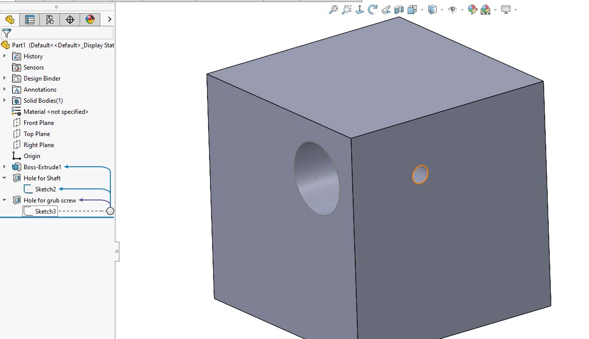
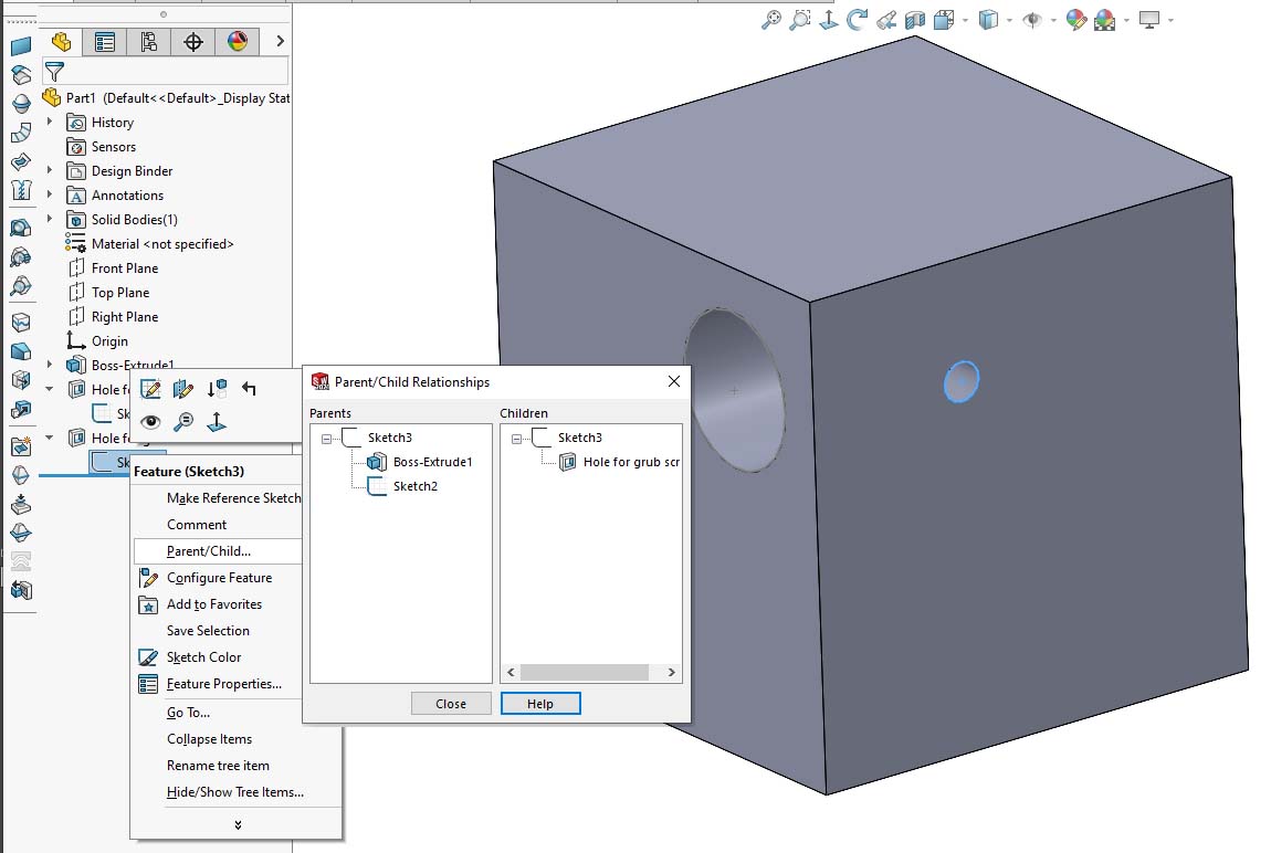
The same information can be viewed by right-clicking a feature and selecting Parent/Child. However, moving around the tree and seeing all the relationships dynamically is far more intuitive and builds up a much better understanding of all the different relationships in the model.
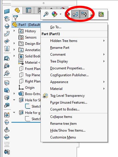
Dynamic reference visualization is turned on by right-clicking the top level of the feature manager tree and selecting the two icons to view parents and children, as shown in the following image.
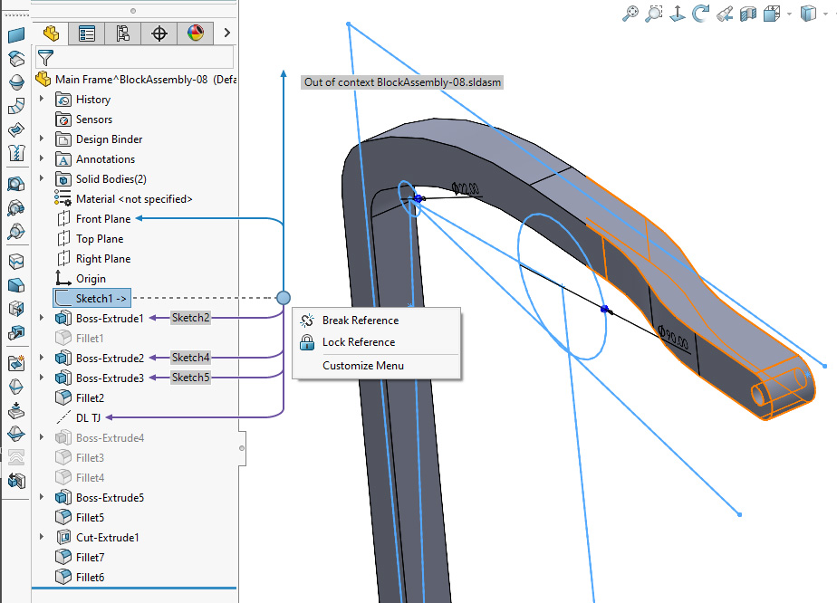
Where features reference other parts or assemblies, relationships between different files can be viewed with the assembly tree. When a part is viewed outside of the assembly where these references are defined, the arrow will point up past the top of the tree with a note saying, “Out of context FILENAME.” This doesn’t mean the reference is broken, it simply means the feature that is being referenced isn’t shown on the feature manager tree. The name of the file that is being referenced is conveniently given. These external references can also be broken, locked, or unlocked from within the feature manager tree.
NOTE: Once an external reference is broken, this cannot be undone — it can’t simply be reactivated.
Digging deeper into sketch relations
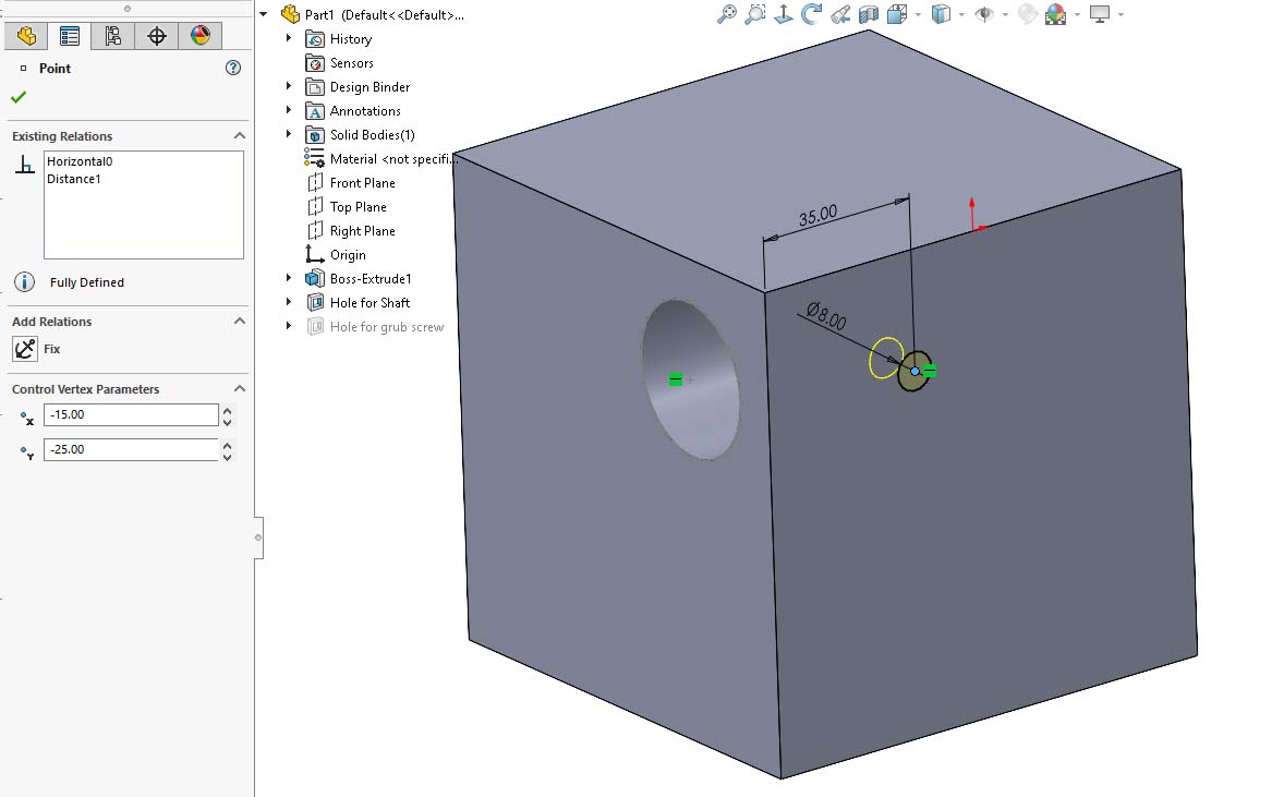
Dynamic reference visualization shows us which features contain relationships to a given sketch. However, it doesn’t allow us to see specifically which dimensions and geometric relations in the sketch reference the feature. Similarly, it doesn’t tell us which geometry in the parent feature is being referenced. The best way to get this kind of detailed information is by using the Display/Delete Relations PropertyManager. This powerful tool is viewed while editing the sketch. To open it, simply click the icon on the command manager (Sketch tab).
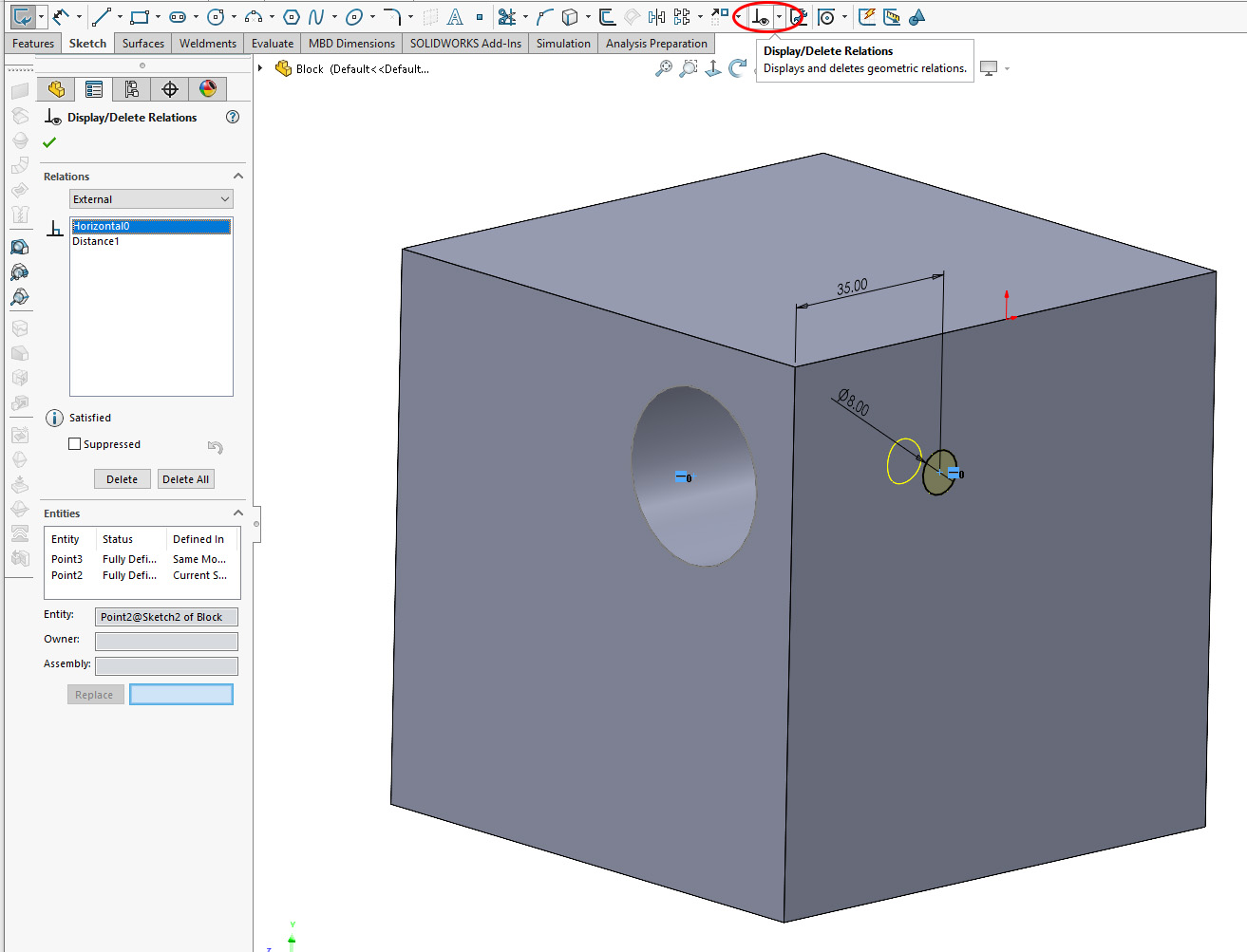
With the Display/Delete Relations PropertyManager open, you are presented with a list of all the relations in the sketch, including geometric relations and dimensions. Frustratingly, these are given different names than the ones you can assign to dimensions and use in equations. Instead, they are simply numbered according to the order they were created in the sketch. However, the tool allows you to identify which features are being referenced once you get used to it.
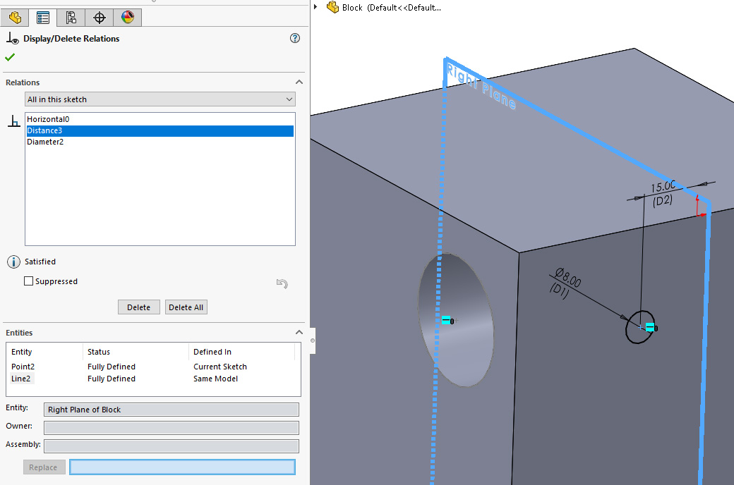
Firstly, you can filter the list of relations using the dropdown above the list or by clicking on a dimension or a feature. Selecting a relation from the list does two things. Firstly, it highlights the referenced entities, even if they were hidden. Secondly, it populates the Entities list within the PropertyManager. Although entities are given strange names within the list, when they are selected, their actual names appear under Entity, which is much more useful.
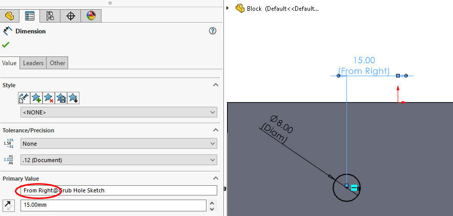
Naming dimensions and displaying their names
Dimensions are all given unique names with a sketch, which can be used within equations and help to identify relationships. These can be displayed while editing a sketch by turning on the option in the Hide/Show Items menu.
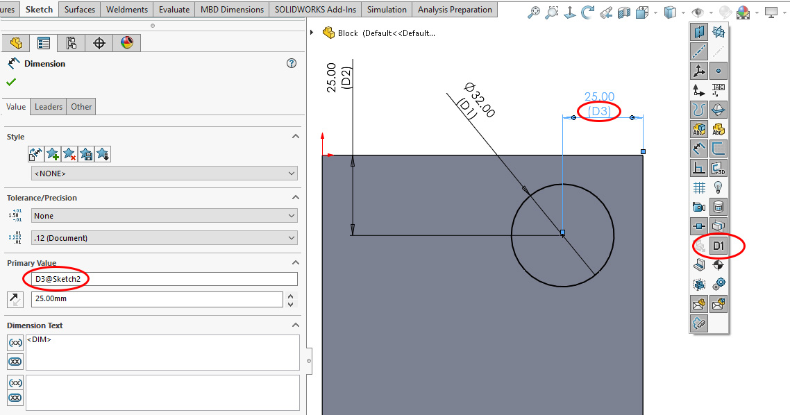
When sketches, features, and dimensions are given meaningful names, it becomes much easier to understand the intent of a model. For simple models, naming everything can be an unnecessary waste of time. However, if you’re getting confused about how the relationships in a model relate to each other, naming everything can really help to bring clarity and make tracing relationships much easier.
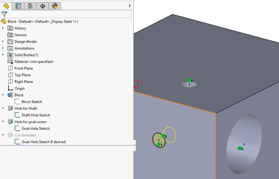
Using derived sketches
When parts and sub-assemblies need to reference each other within an assembly, things can quickly get very messy. Often the best way to handle this is to define all the shared geometry in layout sketches and then bring these into the parts that must reference them as derived sketches. Once the derived sketch is created in a part, all the individual references made to entities in this sketch can be traced within the part without needing to trace references between parts and assemblies. A derived sketch can reduce a large number of separate references between files to a single, easily understood one.
Derived sketches are an exact copy of a sketch that is dynamically linked to the original. It is not possible to change any dimensions or add any features to a derived sketch — it appears as fixed geometry that is driven by the original sketch used to define it. While the lengths of lines and their angle to each other within a derived sketch cannot be changed, the position and orientation of a derived sketch must be defined by adding a few relations.
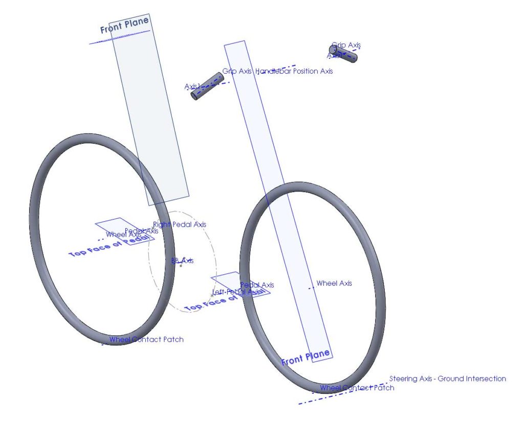
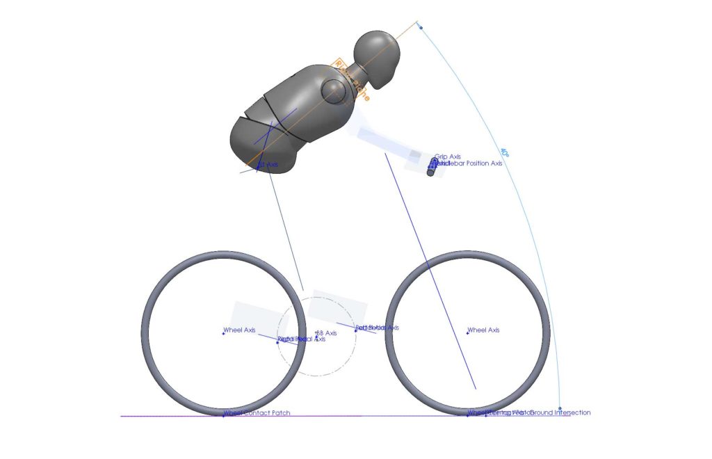
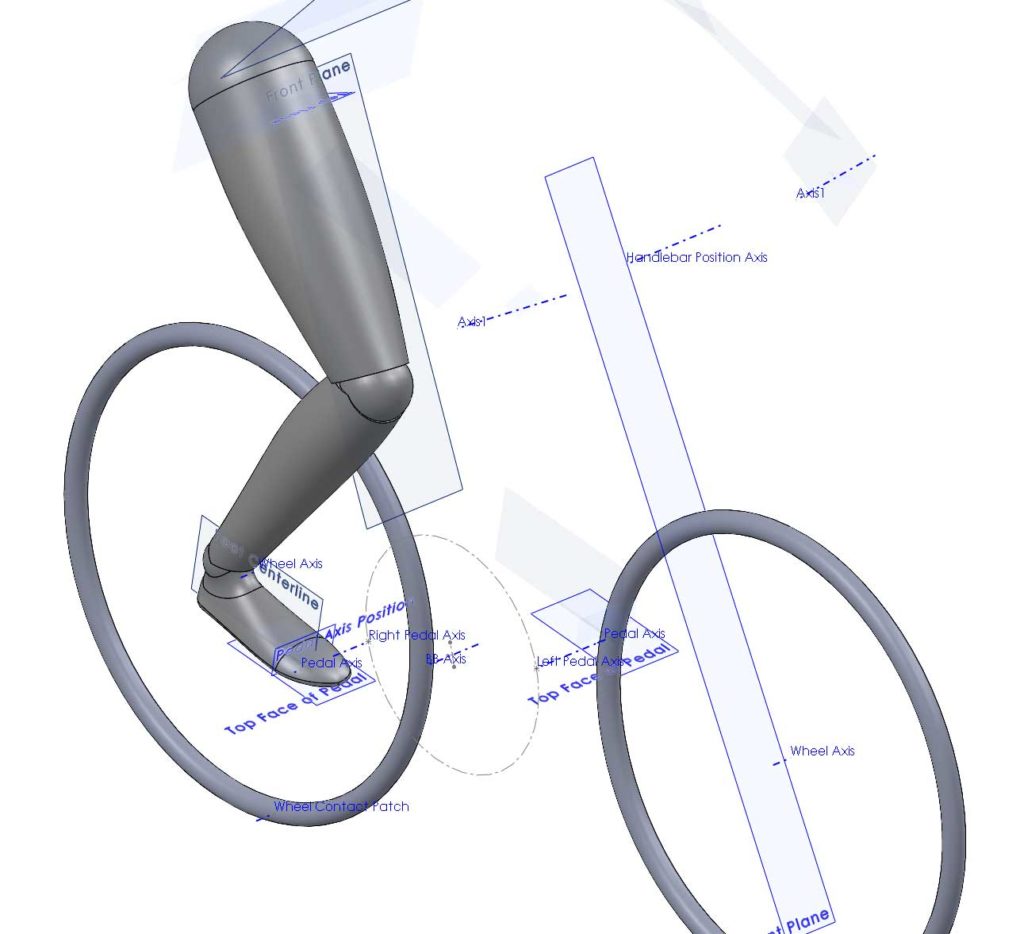
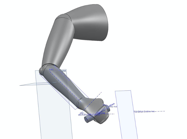
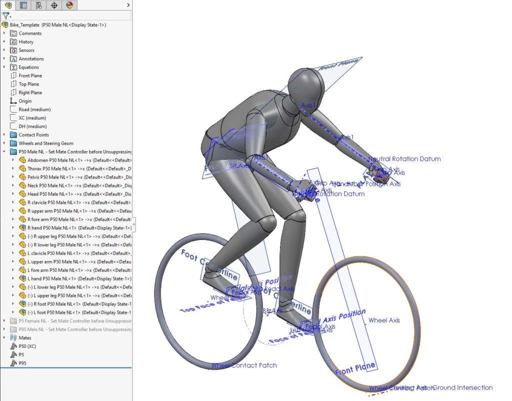
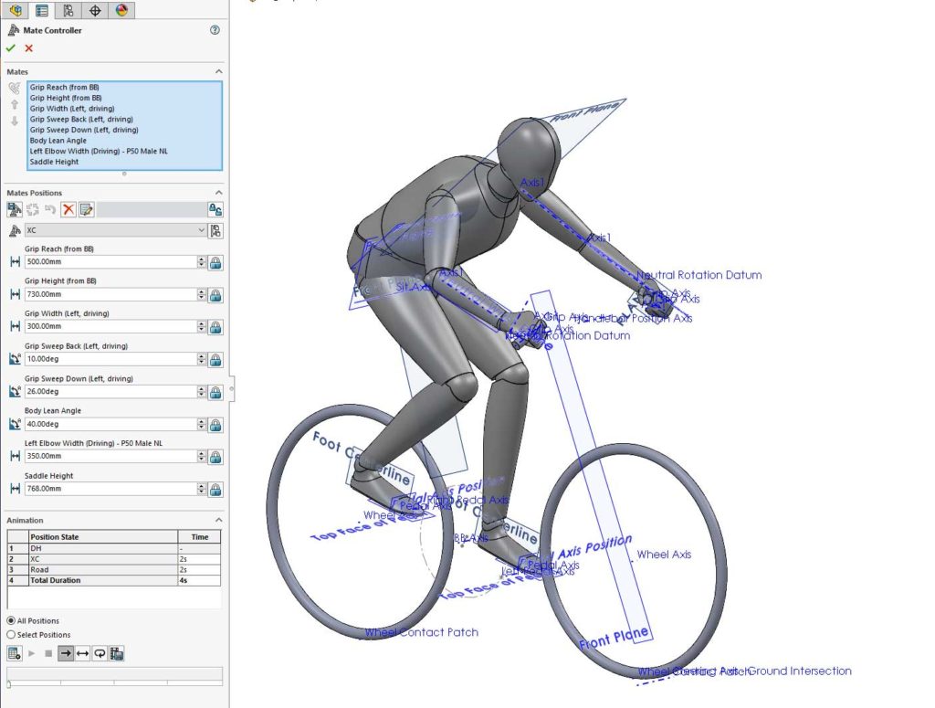
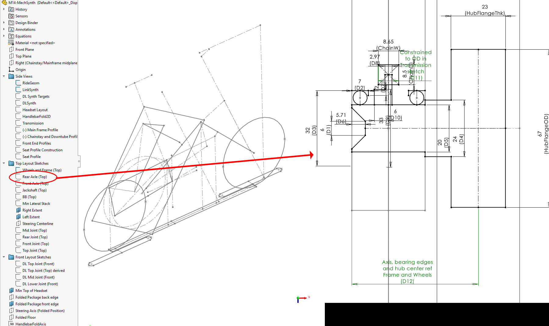
Layout sketches may be defined within the master assembly file or within a master part file. While the assembly may seem like the most logical place for the layouts, and placing them here can work, it can also be more convenient to use a master part. Using a master part for all the layout sketches means it’s possible to work on the top-level definition of the assembly without having the assembly open. This means model updates happen much faster, and if changes are going to make parts fail, you can deal with this later once the assembly-level changes have been worked out. In my recent article about mechanism synthesis for a folding bicycle, I defined the mechanism in a master part. This allowed an optimization script to loop through the part, solving thousands of different configurations efficiently. The assembly file for this bike includes the master part, allowing other parts to reference it. In this way, the link lengths and joint positions are driven by the master part file.
Derived sketches can be created within a single part, allowing a sketch to be effectively copied from one position and orientation to another. Most often, however, a derived sketch will be created by referencing a sketch in another part file, such as a master assembly or master part.
A derived sketch is created by selecting a sketch and a plane and then Insert > Derived Sketch. The selected sketch is the original sketch to be copied, and the plane is where the new sketch is to be located.
To create a derived sketch that references a sketch in a different part of an assembly, both the original sketch and the location for the new sketch must be in the same assembly. The part that is to contain the new sketch must be editable, which generally means selecting Edit in Context before selecting the sketch and plane and then creating the derived sketch.
It is a very good idea to maintain consistent names for derived sketches. The master part or assembly containing all the original sketches defines how they are named. Where these serve as the basis for derived sketches in other parts, the exact same name should be given. Where this would result in multiple sketches with the same name, simple as B, C, D, etc., onto the end of the name. SolidWorks will always add “derived” onto the end of the name for any derived sketch when displaying it in the feature manager tree. It can also be useful to have a naming convention for layout sketches which includes the plane on which they are sketched. For the folding e-bike I’ve been designing, the master part contains lots of derived sketches defining the bicycle geometry, folding mechanism linkages, transmission, and bearing arrangements. I grouped these by sketches on the Right plane, Top plane and Front plane.
Keeping control of complex parametric models involves using a combination of dynamic reference visualization, sketch reference manager, naming conventions for sketches and dimensions, and derived sketches.