Rendering software is increasingly being put to use by design engineers to create downstream product collateral used to support, maintain and sell products–often before the product even exists in physical form. Rendered 3D models are also created and used early in the design process to speed the process of obtaining customer or management approval.
Rendering vendors are working hard to make it easier for users to import 3D models and have incorporated features specific to the the way engineers work. After all, the engineering workflow is quite different from those of users in the arts and entertainment markets.
Read more on rendering software in the Design World feature A Picture’s Worth a Thousand Words: Why Rendering is Increasingly Important to Product Development.
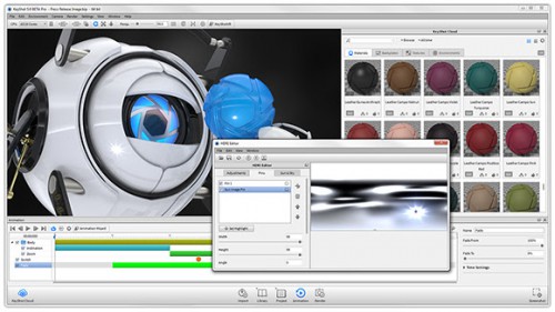
KeyShot 5 for rendering and animation
Luxion has recently released the latest version of its KeyShot rendering software, touted to be the first real-time ray tracing and global illumination software. By providing faster rendering speed and capabilities, users can create images, animations and interactive visuals throughout the product development process quickly and easily.
KeyShot 5 introduces enhanced usability and pro-level features that allow engineers, designers and 3D professionals to make their workflow more efficient and take their visuals to the next level. The software’s new streamlined interface offers new features for a faster rendering and animation workflow, the ability to work with materials faster and more powerful new animation features.
What’s new?
KeyShot Cloud. Online library where users can download new resources and share their own custom assets. Opening the KeyShot Cloud enables easy drag-and-drop downloading of new resources into their local KeyShot Library, and quick search features and filters to find the perfect resources for a scene. All resources remain on a user’s computer with a copy of the resource uploaded to the KeyShot Cloud and no scene or personal info stored online. The KeyShot Cloud is accessible directly from inside KeyShot and online here.
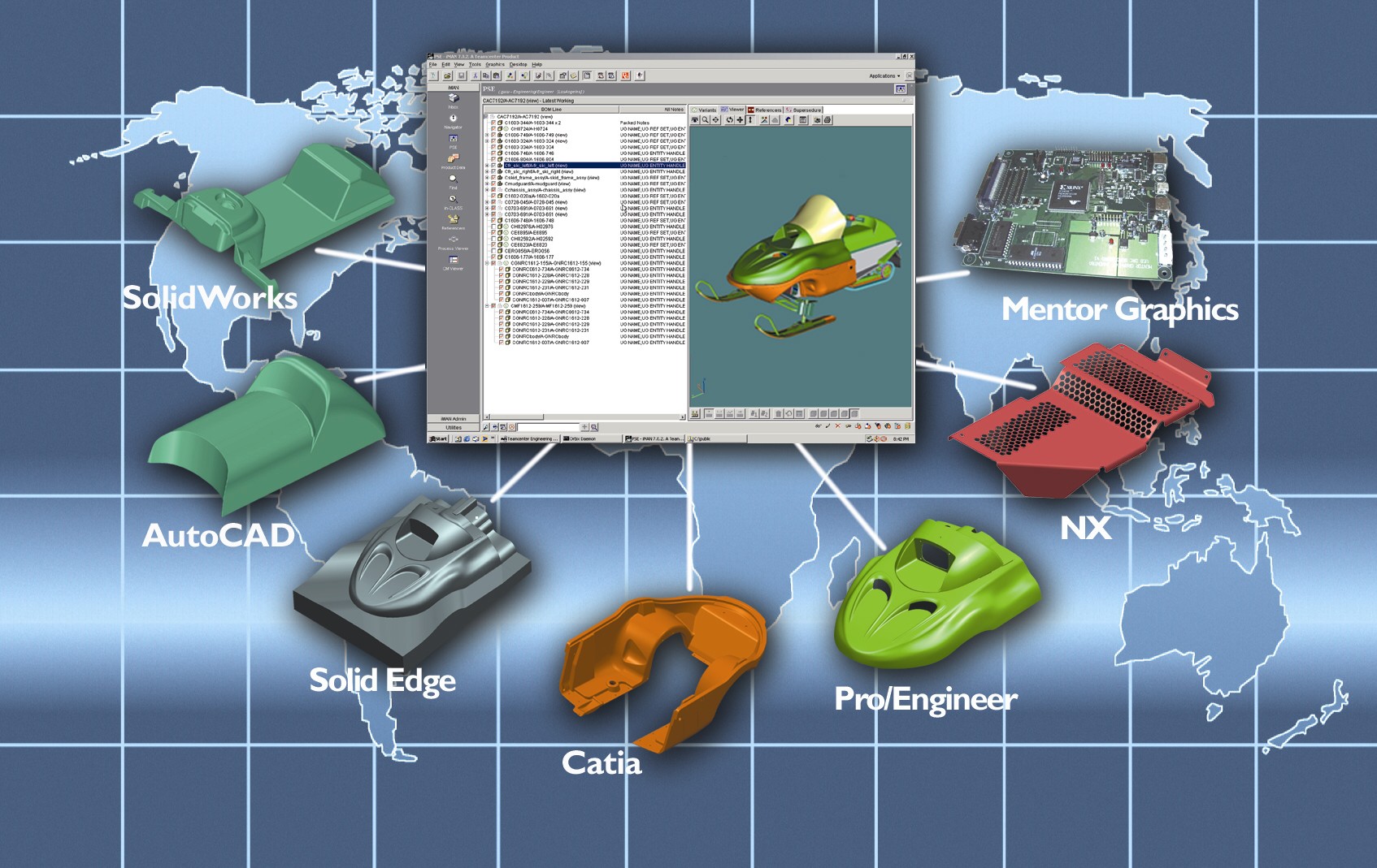
NURBS Ray-tracing. NURBS ray-tracing delivers more accurate geometry with smoother edges. This new import feature gives users the option to import and render NURBS geometry from their favorite 3D modeling application. The advantage is crisper visuals and smaller file sizes over data imported as triangle that can display edges and gaps on close detail shots. NURBS import is currently available for all geometry formats, including Creo, CATIA, Inventor, NX, Rhino, SolidWorks, Solid Edge, STEP, IGES, Parasolid and ALIAS. Available with KeyShot Pro versions.
Instancing. Instancing allows users to duplicate parts in KeyShot and on import without increasing file size. Instancing of parts is available within KeyShot as a Pattern tool and completely automated in select KeyShot plugins. All instances can be treated separately for quick appearance studies or linked to apply materials quickly, but will all update when LiveLinking or update geometry is used.
Fade Animation. The new Fade animation allows users to quickly apply an animation that fades parts from one opacity level to another. Through KeyShot Animation users add individual transforms that add animations with a click of a button instead of managing keyframes. Just as simple, Fade animations can be applied while adjusting the opacity of parts and groups on-the-fly which allows users to see the update in real-time as animations are created. Available with the KeyShot Animation Add-on.
Sun & Sky System. KeyShot 5 introduces a new Sun & Sky system for automatic creation of physically accurate geographic lighting. Preset resolutions and locations together with day selection, time and turbidity sliders allow the creation of unlimited daylight scenarios. Custom Sun & Sky environments can be created by users as well and combined with other lighting options available in the KeyShot HDRI Editor. Available with KeyShot Pro versions.
KeyShot 5 is available now. Pricing starts at $995. The entire list of features in KeyShot 5 can be seen and downloaded in a What’s New guide that includes information on how each feature works.

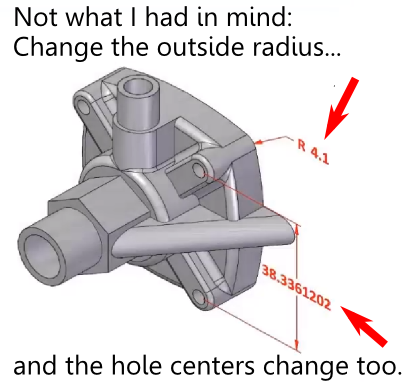 What is the failed promise of parametric CAD? In short, model reuse.
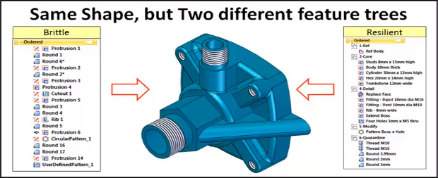
 The model brittleness problem inherent with parametric feature-based modeling is a really big deal. And it’s something, honestly, that I don’t have a great answer for. I’ve even asked a few power users who I know, and their answers seemed to involve a bit of hand-waving, and a reference to having lots of experience.
 Direct modeling—a syncretic melding of concepts pioneered by CoCreate, Trispectives, Kubotek (and many others)–has shown the most promise to cure the parametric curse.