• Skip to primary navigation
  • Skip to main content
  • Skip to primary sidebar
  • Skip to footer

3D CAD World

Over 50,000 3D CAD Tips & Tutorials. 3D CAD News by applications and CAD industry news.

  • 3D CAD Package Tips
    • Alibre
    • Autodesk
    • Catia
    • Creo
    • Inventor
    • Onshape
    • Pro/Engineer
    • Siemens PLM
    • SolidWorks
    • SpaceClaim
  • CAD Hardware
  • CAD Industry News
    • Company News
      • Autodesk News
      • Catia News & Events
      • PTC News
      • Siemens PLM & Events
      • SolidWorks News & Events
      • SpaceClaim News
    • Rapid Prototyping
    • Simulation Software
  • Prototype Parts
  • User Forums
    • MCAD Central
    • 3D CAD Forums
    • Engineering Exchange
  • CAD Resources
    • 3D CAD Models
  • Videos

Inventor

Solving the CAD concurrency problem

June 15, 2012 By Evan Yares 12 Comments

Earlier this week, I was doing some software testing on my lab machine. It’s a really nice Z1, on loan to me from HP. It has an 8-core high-end Intel processor. I brought up the process monitor as I worked, and watched, somewhat amused, as Autodesk Inventor pegged one core at 100% for several minutes, while the other cores sat there, doing almost nothing.
Really Big Sketch
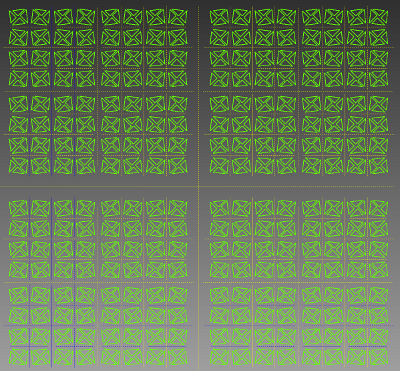
This is a really big sketch. CAD programs don't like these.

It wasn’t Inventor’s fault. Well, not really. The particular test I was doing was designed to push the 2D sketcher in Inventor to its limit. It contained 1024 triangles, connected with over 3072 constraints (I didn’t count exactly.) That sketcher uses a component called 2D DCM (Dimensional Constraint Manager), part of the D-Cubed group of software components, developed and sold by Siemens PLM Software.

Many well-known CAD programs use D-Cubed software. It’s the stuff that, when you push and pull on a sketch (or a CAD model) figures out what you’re trying to do, and calculates the resulting shape. 2D DCM is often called a “constraint manager,” or a “solver.” Built into its heart are a bunch of very complicated algorithms for solving systems of linear equations. It’s PhD level stuff.

In the case of my testing, it was 2D DCM that used all the power of one core, but ignored the other cores in my computer – essentially, leaving 7/8 of the power that HP built into the computer untapped.

So, here’s the question: Why doesn’t Siemens PLM just tell their programmers to fix 2D DCM, so it can use multiple cores? Why not rewrite it to support concurrency? If they did that, it’d solve a lot of other problems at the same time—for example, it would make creating cloud based CAD systems, that run across multiple processors and servers, a lot easier to implement.

As a start, 2D DCM has been thread-safe since 2009. A CAD system can run multiple instances of the program on parallel processors, without any significant performance hit.

So it does run on multiple cores. Problem solved?

Hardly.

In my test, I’d created a 2D sketch in Inventor. where moving any one node or edge required the system to recalculate all of the lines in all of the triangles.  All 1024 of them.  There were no independent constraints, where making a change would not affect other geometry. They were all interlinked.

Suppose Autodesk’s programmers had set up Inventor to use multiple instances of 2D DCM on multiple cores. How could a problem such as mine be partitioned to use those multiple instances?

The answer is: it couldn’t. Running 2D DCM on multiple cores allows those multiple instances to solve independent constraints. Not interlinked constraints.

Let me see if I can paint a picture of the problem. When I was a kid, I used to play a game called pick-up sticks. The idea was to dump out a bunch of long sticks on the floor (or table), creating a tangled pile. Each player, in turn, would remove a stick from the pile without disturbing the remaining ones.

Pick-up Sticks

Imagine several people playing pick-up sticks, but instead of waiting in turn, all of them trying to remove sticks at the same time. Concurrently. That’s pretty analogous to the problem of partitioning the data in a sketch in a way that it’s possible to use parallel solvers. There’s no easy way of partitioning the equations representing the system of constraints in such a way that they can be solved in parallel.

2D DCM has been around for quite a long time, as CAD component software goes. When it was designed, the programmers likely looked at the issue of parallel computing, shuddered, and decided to focus on making the software actually work right in the first place. It probably made sense at the time: Multicore processors, and even parallel computers, were rare.

Over the years, some things have changed. Multicore, parallel processors, clusters, and cloud computing are now commonplace. And there have been advances in math. Do a search on Google Scholar for “parallel solutions of linear systems” and you’ll get a lot of results. Still, adding parallel support into a tool like 2D DCM isn’t just a matter of writing some lines of code. It might involve tearing it down to the ground, and rebuilding it with a completely new architecture.

Is Siemens willing to invest what would likely be a princely sum in rebuilding their D-Cubed products from the ground up? I can’t answer that question. If I asked the folks at Siemens, and they told me, I’d not be able to tell anyone else. Trade secrets, you know. But I can say that I hope they are looking at this problem, because it’s one of the key limitations that get in the way of developing next-generation high-performance CAD software.  The kind that can run on multiple cores, multiple processors, clusters, or the cloud.

I wrote this post in response to a commenter, who was raising the issue of the lack of multicore support in current CAD systems. I think his concern is valid, but I wanted to make the point that this is not a simple problem to fix, whether in geometric constraint managers, or geometric modeling kernels. It’s like the pick-up sticks problem: Really difficult, even if you throw big piles full of money at it, and wave fat paychecks at PhD mathematicians.

Still, there are people working on these problems. Next week, I’ll be writing a bit about Cloud Invent, a tiny company that may have made a breakthrough in geometric constraint modeling.


Pick-up sticks image courtesy David Namaksy, boardgamegeek.com

Filed Under: Evan Yares, Featured, Inventor, News, Siemens PLM Tagged With: Autodesk, cloud, Cloud-Invent, Concurrency, D-Cubed, DCM, Inventor, Multicore, Siemens PLM

Autodesk provides real-time DFM for plastic part design

April 3, 2012 By Evan Yares 1 Comment

There’s a lot of benefit to be had by doing manufacturability analysis (DFM, Design for Manufacturing) early in the design process, rather than waiting until later, when design changes are far more expensive.

A couple of years ago, Autodesk Labs previewed a product, Project Krypton, which ran inside of 3D CAD programs (including Autodesk Inventor, DS SolidWorks, and PTC Pro/E), and gave real-time feedback on manufacturability, cost, and sustainability of plastic injection molded parts.


Project Krypton has now reappeared, in commercial form, as Autodesk Simulation DFM (Design For Manufacturing.) It works as a plug-in, running in a number of versions of Inventor, Inventor LT, Wildfire, Creo, and SolidWorks. It is available as a subscription benefit for Autodesk Simulation Moldflow Adviser 2013 subscribers, or as a stand-alone product, at US$2,000 for a license to run on any of the supported CAD platforms.

It’s reasonable to argue that engineers who are designing plastic parts should know enough to be able to recognize manufacturability, cost, or sustainability problems. And, if they don’t, they should take the time to learn (for example, by taking a few hours to read any of the many freely available books on the subject, such as General Design Principles for DuPont Engineering Polymers.) Even though that argument is reasonable, it doesn’t recognize human nature. People, even engineers who should know better, don’t always take the time to “read the manual.” Often, it makes sense to build the “manual” into the tools that engineers use every day. Simulation DFM does that, and quite a bit more.

For inexperienced designers, Simulation DFM provides quick feedback to help them avoid rookie mistakes. It’s sort of like an “idiot light” on a car’s dash, that warns you when something is wrong. And while old-hands might say they prefer gauges to idiot lights, experience has shown that idiot lights are useful to experts (even F1 drivers and fighter pilots) for catching their attention, and getting them to actually look at the gauges.
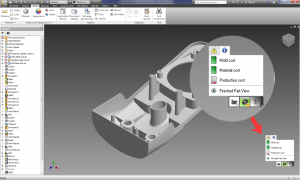
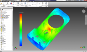
Simulation DFM doesn’t require that users have any background in molding simulation. It uses “green is good, yellow is not so good, and red is bad” indicators to identify potential manufacturing, cost and sustainability issues, showing the source and location of the problem. Any issues that pop-up can be expanded upon, to provide more detail on the exact source of the problem, even showing, for example, mold filling analyses.  The software requires no additional training, and doesn’t require much user input.

The open question with Simulation DFM is “how good is it?” Since it’s based on the Autodesk Moldflow simulation engine, it should be quite good, even for relatively complex parts (though it doesn’t support multi-body parts.) Yet, even if its capabilities were modest, it would still be of value, in either helping beginning designers to learn good design practice, or helping old-hands catch mistakes they might have otherwise missed.

As an engineer, I’ve long had the habit of using the “anything I can see” test to evaluate the usefulness of software. I look around the room, looking at anything I see, and ask myself “would this software have helped the engineers who designed these things?” In this case, as I sit in my office, I can see at least 20 items (without even turning to look behind me), each with multiple injection molded parts, that would have been quicker, easier, and less-expensive to design, had their engineers had access to up-front DFM software, such as Autodesk Simulation DFM.

The most significant benefit of Autodesk Simulation DFM comes not from its detailed capabilities, but rather from its clean integration into the design workflow. A user need not press a button, or take any specific action when designing a plastic part to benefit from it. All they need to do is notice, as they design, whether the software has picked up any obvious red-flags.

That Autodesk decided to make Simulation DFM available for Pro/E, Creo, and SolidWorks (as well as Inventor) shows that rational minds sometimes do prevail: There are untold thousands of PTC and SolidWorks customers who design plastic injection molded parts, and who are unlikely to switch primary CAD tools any time soon. The challenge Autodesk is going to face is in getting Simulation DFM in front of those users (since PTC and SolidWorks sales reps and dealers are not likely to recommend it.) Maybe not so much of a challenge: Many of Autodesk’s existing Moldflow customers are Pro/E and SolidWorks users.

There’s a certain charm to software that does something of great value, but does not impose any extra demands on its users. Autodesk Simulation DFM looks like it may be that kind of product.

Autodesk www.autodesk.com

Autodesk SimSquad simsquad@autodesk.com

Filed Under: Autodesk, Autodesk News, Creo, Evan Yares, Featured, Inventor, News, Pro/Engineer, Simulation Software, SolidWorks Tagged With: Autodesk, CAE, Creo, DFM, Inventor, Moldflow, Pro/E, simulation, SolidWorks

High-tech tools for a cool ride

January 23, 2012 By Laura Carrabine Leave a Comment

When Marcus Hays first heard about an electric bike, he was less than enthusiastic. Why load a bike with battery weight, turning the human motor into passenger in the process? That was 1995 and Hays was working with Lee Iococca to develop electric cars and bikes.

Electric bikes use less than 1,000 watts of total power and can be used on bike paths. When Hays first encountered these hybrid vehicles, most models were imported from a variety of countries. They relied on an injection molding manufacturing process which produced parts made of a variety of thermoplastics. While initially pleasing in appearance, the plastic parts raised questions of reliability and tended toward unsightly discolorations and dangerous cracks. “As an advocate for electric bikes,” said Hays, “I felt these problems had to be solved.”

To efficiently produce a more reliable and environmentally friendly electric bike, Hays’ company Pi Mobility took a minimalist approach. For Hays and his team, the longer a product will last is a key factor in making it more sustainable. Rather than rely on brittle plastics for a multitude of parts, Pi Mobility used an elegant, solitary arch of recycled aluminum for its bikes’ iconic frame. The recycled aluminum lasts longer than plastic and the batteries and electronic components reside safely within the aluminum tube rather than an injection molded plastic battery enclosure.

Recycled aluminum requires one-thirteenth the amount of electricity to produce compared to virgin aluminum. And, a Pi Mobility bikes produces 300 lbs of carbon dioxide per 12,000 miles of travel, making it 20-30 times more efficient than a motorcycle or cart. The single tube used in the PiCycle and PiMoto models’ battery agnostic design means they can conceivably handle any battery or chemical process that produces electricity, allowing for easy upgrades in the future.

Thanks to the less labor-intensive design of the single tube, Pi Mobility has been able to maintain production in the US and still be profitable. “We can form a tube in about 30 seconds,” said Hays. “With the help of Autodesk software, changes to the design can be embedded very quickly. Our manufacturing method offers very rapid scale at competitive prices, but it also reduces the required labor to a fraction of more traditional electric bikes. By producing our bikes locally, much of the transportation carbon that often affects even environmentally sustainable good can be eliminated.

The company’s testing program makes durability and sustainability its top priorities, before appearance. Pi Mobility seeks to combine all three elements at every opportunity. The Autodesk solution for Digital Prototyping helped the company to optimize its design and bring new products to market faster.

Hays said,” We use Inventor, Vault, Alias Design, and Showcase. Our design team took to the software immediately. After just three weeks the team produced a 3D digital prototype using Inventor. It proved that by increasing the diameter of our tube by a half inch, we could save $335,000.”

Pi Mobility

www.picycle.com

Autodesk, Inc.

www.autodesk.com


Filed Under: 3D CAD Package Tips, Autodesk, Autodesk News, CAD Blogs, Inventor Tagged With: 3D CAD, Alias prototyping, Autodesk, electric bikes Vault, Inventor, Marcus Hays, Pi Mobility, Showcase

Printer shifts from 2D to 3D

December 22, 2011 By Laura Carrabine Leave a Comment

Voith Paper decided to improve its design process across its centers of competencies around the world. Each center specializes in particular parts of a paper machine: due to its massive size and complexity, a finished machine requires design input from several design centers. Voith knew that speeding up its design and manufacturing processes would mean aligning its dispersed design teams.

Moving its designers onto a standard platform worldwide meant integrating the Autodesk manufacturing technology with other key enterprise systems. As a result, Voith has synchronized its design teams and achieved new heights in speed and efficiency levels. “By integrating our 3D models into our SAP ERP system, we can make design changes more quickly. Every engineer has access to the same information, said Voith’s Olaf Spitzer. “This allows us to respond to our customers’ needs faster.”

Frederich Spitzer, PDM Support Manager, IT Solutions for Voith, “We are organized into centers of competencies, so every location with manufacturing capabilities has competencies for a certain product in the finished machine. By installing a common Inventor SAP ERP system with help from Autodesk Consulting, we bring all the information that is generated by these different locations together in one system.”

Voith is also gaining efficiencies associated with the enterprise parts management system built by Cadenas GmbH. The PART system reduces design time by providing access to components and assemblies. Design and development engineers are able to see relevant part information such as price, delivery time, and release status in one user interface.

With a common database, Voith’s design team now uses the same items with the same information. By streamlining parts numbers, Voith facilitates procurement, inventory, and maintenance.

Today, Voith is creating more accurate designs faster. Each machine is designed by several of Voith’s centers of competencies and then assembled at the customer site. Since adopting Inventor, Voith has reduced assembly problems.

“By integrating Inventor with our ERP system, we can respond quicker to our customer needs,” said Olaf Spitzer. “We are able to show them designs before we build a machine. For one project in China, a company ordered parts of a paper machine. We showed them the design and they had changes which we were able to make overnight. We then presented the new design to the customer the next day and secured an order.”

Autodesk

www.autodesk.com

Filed Under: Autodesk, Autodesk News, Inventor Tagged With: 2D, 3D, Autodesk, Cadenas, ERP, Inventor, SAP, Voith Paper

Racing team relies on suite of software products

November 2, 2011 By Laura Carrabine Leave a Comment

Australia-based racing team, Kelly Racing, has been using Autodesk products for a range of uses – from precision design to validating new car components — all without hitting the track for physical testing. Given that the period between races is often a window of less than three weeks, Autodesk Inventor Professional, Autodesk Simulation CFD, Autodesk Simulation Multiphysics, and Autodesk Vault Professional software are crucial to enabling Kelly Racing to turn around new components in a timely manner and secure wins in half the time of most racing teams. “It is critical for us to be fast and efficient in every facet of our business,” said Rick Kelly, team racer and co-owner.

“Autodesk provides the technology and expertise to streamline our entire design process, so we can beat our competition on the track and in the marketplace. Now that we have incorporated Autodesk Product Design Suite, it has enabled us to further enhance our workflow.”

Following a race weekend, the drivers brief Kelly Racing’s in-house design and engineering team on what precisely went right and wrong during the race. The designers then set to work with Inventor Professional software to make modifications to the existing car parts that can enhance performance and save the team time. For example, improvements to the front end of the car, in particular the suspension assembly, has increased traction and grip by 8%, leading to faster lap times or shaving 1% of total car weight through design and material optimization.

Even the most minor modifications play a vital role in a sport where a fraction of a second can be the difference between first and 21st place. Engineers then test revised designs with Autodesk Simulation CFD to optimize aerodynamic performance and ensure the components are able to perform at speeds of up to 300 kilometers (188 miles) per hour. Autodesk Simulation Multiphysics software is also used to predict and validate the mechanical performance of the new components. Autodesk Vault Professional data management software helps manage the design process from initial concept to final release, providing the engineering team with greater control over the design process right up until the component or part is manufactured, released to the race department and put on the car.

Embracing Digital Prototyping has been a winning strategy for Kelly Racing. A new racing team typically takes six or more years to register its first win, but just barely into its third season, Kelly Racing has already scored two victories along with nine podium finishes.

Autodesk, Inc.

www.autodesk.com

Filed Under: 3D CAD Package Tips, Autocad Blogs, Autodesk, Autodesk News, CAD Package, Inventor, Simulation Software Tagged With: Autodesk, CFD, digital prototyping, Inventor, Kelly Racing, Multiphysics, vault

Analysis linked to CAD

October 25, 2011 By Laura Carrabine Leave a Comment

Comsol’s latest update to its flagship multiphysics software Comsol 4.2a includes enhanced LiveLink capability. The new associativity to between Comsol and Creo packages means any changes to a feature in the Creo CAD model automatically updates the geometry in Comsol Multiphysics while retaining physics settings.

All parameters specified in Creo can be interactively linked with your simulation geometry which enables multiphysics simulations involving parametric sweeps and design optimization to sync up with the CAD program. The LiveLink for Creo includes all the capabilities of the Comsol CAD Import module and enables import and defeaturing of CAD files from all major CAD packages.

In addition, the Parasolid geometry kernel from Siemens PLM Software is now the default geometry kernel for those who use the CAD Import module and the LiveLink products for CAD. Parasolid enables the handling of more advanced geometry objects for any of the LiveLiink products, including versions for AutoCAD, Inventor, Creo Parametric, Pro/E, SolidWorks, and SpaceClaim.

Comsol

www.comsol.com

Filed Under: Autodesk, Creo, Inventor, Pro/Engineer, Siemens PLM, Simulation Software, SolidWorks Tagged With: AutoCAD, CFD, COMSOL, Creo, FEA, Inventor, LiveLink, Multiphysics, parametric CAD, Parasolid, PTC, Siemens, SolidWorks, SpaceClaim

Colossal 400-ft truck completely designed in CAD

October 17, 2011 By Laura Carrabine Leave a Comment

Perkins Specialized Transportation Contracting (Perkins) provides highway transportation services for long, heavy, and oversized objects. Its engineers recently used Autodesk Simulation software for the custom design of a 400-ft long truck specifically created to transport nuclear generators.

The truck took almost three years to design and gives a safe and efficient way to transport enormous and often radioactive components that were once considered immovable. The truck successfully carried four steam generators from the San Onofre Nuclear Generating Station in southern California to a disposal site in Clive, Utah.

The vehicle is longer than a football field, has 192 wheels and 48 axles, each of which can be turned independently. The truck can effectively navigate sharp turns and different road grades. Autodesk Digital Prototyping software helped Perkins engineers use a 100% digital approach to create a truck capable of carrying a 400-ton payload over 750 miles.

The engineering team started with 2D sketches of the transporter created in AutoCAD. Then, they imported the files into Inventor to model them in 3D. The software helped Perkins engineers perform motion analysis and check for interferences throughout a full range of motion as the various axles turned and rotated.

The team also used Autodesk Simulation software to optimize its designs, ensuring that the transporter had only the support beams necessary to successfully distribute weight among the various axles. The stress analysis ensured that no axles were overloaded and that the truck was as strong and light as possible.

Autodesk, Inc.

www.autodesk.com

Filed Under: Autocad Blogs, Autodesk, Autodesk News, Inventor Tagged With: 3D CAD, AutoCAD, Autodesk, Inventor, nuclear, Perkins, simulation

3D Mice can now be used with any application

March 31, 2011 By Laura Carrabine Leave a Comment

3Dconnexion today announced 3DxWare 10, a breakthrough driver platform that extends the usage of 3D mice to any application, from Microsoft® Office® to internet browsers and from media players to games. With over a million units sold, 3Dconnexion 3D mice are the tool of choice for engineering and design professionals working in sophisticated 3D environments. And now with 3DxWare 10, 3Dconnexion 3D mice can also handle everyday applications with ease. Beta versions of 3DxWare 10 for PC and Mac can be downloaded for free from www.3dconnexion.com/anywhere.

Previously, only users of specialist 3D applications benefited from the intuitive, six degrees-of-freedom 3D navigation delivered by a 3Dconnexion 3D mouse. Now, the simple 3DxWare 10 interface allows users to assign keyboard strokes and traditional mouse or joystick movements in any combination to the 3D mouse. Tilt the controller cap to scroll a Web page, twist the cap to adjust the volume in iTunes, or use all six axes to pilot a helicopter in Battlefield Bad Company 2. The choice of application and assignment of the six axes and up to 31 function keys (depending on the 3D mouse model) is entirely up to the user.

3DxWare 10 offers limitless possibilities for incorporating 3D mice into everyday use, including:

Documents and Browsers: 3D mice now offer a compelling alternative to traditional mouse wheel navigation in documents, spreadsheets and Web pages. Gently tilt the 3D mouse cap to scroll the view up or down or twist the cap to zoom in and out.

Games: Most PC gamers rely on a combination of a traditional mouse and keyboard to control their character or camera view, but with 3DxWare 10 a 3D mouse can be used to deliver intuitive and comfortable control in games like The Sims™ 3. It’s also possible for the 3D mouse to emulate a joystick or gamepad for a rich 3D experience in games such as Microsoft Flight Simulator, Wings of Prey and Need for Speed.

Media Players: Controlling the volume, track selection or position is typically handled by the traditional mouse and keyboard shortcuts. With a 3D mouse, you can twist the cap to adjust the volume, tilt the cap sideways to fast forward and rewind, and tilt the cap forward or backward to move between tracks in your playlist. And if the user prefers other controls, they can easily customize the 3D mouse to best suit their needs.

3D Collaboration: 3DxWare 10 also provides a new feature for professional users by allowing multiple 3D mice to be used on one workstation. This innovative development enables easier viewing of 3D models in group design reviews or client presentations.

The 3DxWare 10 beta platform for PC and Mac is available for download at www.3dconnexion.com/anywhere and is compatible with 3Dconnexion’s current line of 3D mice, including the SpacePilot PRO (MSRP $399), SpaceExplorer™ (MSRP $299), SpaceNavigator (MSRP $99) and SpaceNavigator for Notebooks (MSRP $129).

3Dconnexion
www.3Dconnexion.com

Filed Under: 3D CAD Package Tips, Autodesk, CAD Blogs, CAD Industry News, Catia, Featured, Inventor, Pro/Engineer, Siemens PLM, SolidWorks Tagged With: 3D 3Dconnexion, 3Dx Ware, Microsoft

Autodesk unveils 2012 Manufacturing software portfolio

March 23, 2011 By Laura Carrabine Leave a Comment

Autodesk, Inc. introduced its new 3D design and engineering software portfolio for manufacturers, including the new Autodesk Product Design Suite that makes design, visualization, and simulation software easier to adopt, use, and maintain. The complete Autodesk Digital Prototyping software portfolio helps manufacturers to design and build better, more sustainable products, reduce development costs and get to market faster.

Autodesk offers three editions of the Product Design Suite:

Product Design Suite Standard ¾ Foundational product design tools for conceptual design,  intuitive 3D surface and solid modeling, drafting and presentations, featuring AutoCAD Mechanical with Inventor Fusion, Autodesk Showcase, Autodesk SketchBook Designer, Autodesk Vault and Autodesk Mudbox software.

Product Design Suite Premium ¾ Optimized Digital Prototyping and visualization tools for maximum performance that features Standard edition tools along with Autodesk Inventor and Autodesk 3ds Max Designsoftware.

Product Design Suite Ultimate ¾ Advanced surfacing, simulation and tooling for unbeatable design quality, featuring the same tools as the Premium edition along with Autodesk Inventor Professional and Autodesk Alias Design software.

Launched in 2010 and updated this year, Autodesk Factory Design Suite 2012 is a factory layout and optimization solution that helps manufacturers make better layout decisions through the creation of a digital factory model, helping save time and money. It offers factory specific functionality in both AutoCAD Architecture and Autodesk Inventor, combined with Autodesk Navisworks’ visualization and analysis and Autodesk Vault to improve collaboration. New additions to the suite in 2012 include AutoCAD Mechanical for automating mechanical CAD tasks and 3ds Max Design and Showcase for enhancing communication and bids.


As a result of the strategic partnership announced in Oct. 2010, Autodesk and Granta Design Ltd. have built new design methods into Autodesk Inventor 2012 software that help designers estimate a product’s environmental impact and make more sustainable design decisions. The new Eco Materials Adviser in Inventor 2012 addresses sustainable design requirements early in the design process — when it matters most — enabling manufacturers to choose materials that minimize environmental impact without compromising on cost and performance. Powered by Granta’s expert materials database and proven sustainable design methodology, Eco Materials Adviser helps guide material selection and generates eco-impact reports so engineers can record and communicate the benefits of their sustainable design decisions.

Autodesk Inventor Fusion makes its commercial debut following its popular technology preview on Autodesk Labs. It is now included at no extra cost as a companion application to Autodesk Alias Design and Alias Automotive, Autodesk Inventor, Autodesk Moldflow, Autodesk Simulation and AutoCAD products. Inventor Fusion provide robust 3D modeling ease-of-use and direct modeling for rapid design changes. It also unites direct and parametric workflows within a single digital model created in Autodesk Inventor.

Along with the Autodesk Product Design Suite, each product in the Autodesk Manufacturing portfolio offers  new capabilities, spanning conceptual design, engineering, manufacturing, and technical documentation.

AutoCAD Electrical 2012 software expands its support for international standards and     now allows electrical controls designers to view, edit and share their DWG files on web browsers or mobile devices through AutoCAD WS .

AutoCAD Mechanical 2012 software now enables editing 3D models from any source with   Inventor Fusion and intelligent drawing view creation with a new model documentation feature. Also new is mobile and web viewing and editing through AutoCAD WS, so mechanical engineers can spend more time innovating.


Autodesk 3ds Max Design 2012 visualization software enables you to demonstrate the operation of designs in real-world settings, providing seamless aggregation of CAD data and transforming digital prototypes into high-quality visuals with “push-button” rendering, cinematic-quality animation and effects and an extensive material and texture library.

Autodesk Alias 2012 products ― Alias Design, Alias Surface and Alias Automotive software ― make it easier to create accurate 3D models with Class-A surfaces and feature improvements to the technical surfacing process with modeling tools that are dramatically easier to use.

Autodesk Inventor 2012 software provides easier ways to interact with 3D mechanical design data; new opportunities for sharing, accepting and updating CAD data regardless of source and complexity; and high-impact performance and productivity improvements for both users and IT departments.

Autodesk Inventor Publisher 2012 software makes it easy to create highly visual and interactive assembly instructions, operating procedures and technical documentation from 2D and 3D CAD data. Users can publish interactive, 3D instructions in multiple formats directly to iPhone, iPad, and iPod touch mobile devices.

Autodesk Moldflow 2012 software introduces new real-time injection-molding simulation functionality, enabling dynamic evaluation of a range of plastic part design alternatives in a fraction of the time it takes to perform a standard simulation, helping to pinpoint the best design more quickly.


Autodesk Showcase 2012 visualization software is a key element of the Product Design Suite, transforming CAD data into compelling imagery, movies, and interactive presentations to improve the design review process, secure internal buy-in and win competitive bids.

Autodesk Simulation 2012 software, previously known as Autodesk Algor Simulation, offers an all-new user interface as well as Autodesk Vault integration, introducing new revision management capabilities for easier management of design and engineering information.

Autodesk SketchBook Designer 2012 software provides digital sketching and illustration to enhance the creative process. Design professionals can export vector artwork from SketchBook Designer and bring it into Alias as curve data, transforming 2D concept sketches directly into 3D product designs.

Autodesk Vault 2012 product data management software gives workgroups across multiple locations more control over engineering data and documents from design through manufacturing, expanding its integration to additional Autodesk applications, including Navisworks, Inventor Publisher and Autodesk Simulation.

Autodesk, Inc.

www.autodesk.com

Filed Under: 3D CAD Package Tips, Autocad Blogs, Autodesk, Autodesk News, CAD Industry News, CAD Package, Featured, Inventor Tagged With: Alias, AutoCAD, Autodesk, digital prototyping, Inventor, Mechanical, Moldflow, Product Design

3Dconnexion achieves 1,000,000 3D mouse milestone

March 2, 2011 By Laura Carrabine Leave a Comment

3Dconnexion today announced it has shipped more than one million 3D mice, supporting today’s 3D software solutions from companies including Autodesk, Dassault Systèmes,  Siemens, PTC, Google, Microsoft, and Adobe across CAD, digital content creation, architecture and construction, and geographic information systems.

The devices unlock the power of 3D design applications by allowing you to interact naturally with 3D content as if they are holding the model or camera in their hand. Many of the world’s leading companies in industries from aerospace to automotive, consumer goods to electronics, and machine tools to game development, use 3Dconnexion 3D mice to boost productivity, efficiency and the comfort of their design teams.

To mark its “One Millionth 3D Mouse Milestone,” 3Dconnexion will host several activities throughout the next month, offering users the opportunity to win a 3D mouse. For more information, visit 3Dconnexion’s website, Facebook and Twitter.

The core technology inside all of 3Dconnexion’s 3D mice originates from the field of robotics and space exploration. In 1993, a 3D controller was used on the space shuttle Columbia, manipulating the first robotic arm in space, and was the launching point for a family of 3D mice that now help 3D professionals in hundreds of thousands of organizations to design, innovate and create some of the most well known products in the world.

3Dconnexion

www.3dconnexion.com

Filed Under: 3D CAD Package Tips, Autodesk, CAD Blogs, Catia, Inventor, Pro/Engineer, Siemens PLM, SolidWorks Tagged With: 3Dconnexion, Adobe, Autodesk, cad, Dassault, Google, Microsoft, PTC, Siemens

  • « Go to Previous Page
  • Go to page 1
  • Go to page 2
  • Go to page 3
  • Go to page 4
  • Go to Next Page »

Primary Sidebar

3D CAD NEWSLETTERS

MakePartsFast

Follow us on Twitter

Tweets by 3DCADWorld

Footer

3D CAD World logo

DESIGN WORLD NETWORK

Design World Online
The Robot Report
Coupling Tips
Motion Control Tips
Linear Motion Tips
Bearing Tips

3D CAD WORLD

  • Subscribe to our newsletter
  • Advertise with us
  • Contact us
Follow us on Twitter Add us on Facebook Add us on LinkedIn Add us on Instagram Add us on YouTube

3D CAD World - Copyright © 2021 · WTWH Media LLC and its licensors. All rights reserved.
The material on this site may not be reproduced, distributed, transmitted, cached or otherwise used, except with the prior written permission of WTWH Media.

Privacy Policy