• Skip to primary navigation
  • Skip to main content
  • Skip to primary sidebar
  • Skip to footer

3D CAD World

Over 50,000 3D CAD Tips & Tutorials. 3D CAD News by applications and CAD industry news.

  • 3D CAD Package Tips
    • Alibre
    • Autodesk
    • Catia
    • Creo
    • Inventor
    • Onshape
    • Pro/Engineer
    • Siemens PLM
    • SolidWorks
    • SpaceClaim
  • CAD Hardware
  • CAD Industry News
    • Company News
      • Autodesk News
      • Catia News & Events
      • PTC News
      • Siemens PLM & Events
      • SolidWorks News & Events
      • SpaceClaim News
    • Rapid Prototyping
    • Simulation Software
  • Prototype Parts
  • User Forums
    • MCAD Central
    • 3D CAD Forums
    • Engineering Exchange
  • CAD Resources
    • 3D CAD Models
  • Videos

Siemens PLM

Collaboration works to improve CAD simulation

February 21, 2018 By Leslie Langnau Leave a Comment

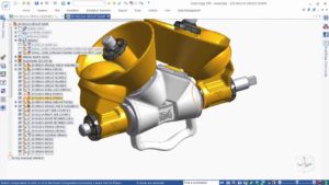
SimScale GmbH (“SimScale”), a provider of the full-cloud engineering simulation platform, announced a collaboration with Siemens PLM Software and Tech Soft 3D to optimize the simulation workflow through better CAD model handling. SimScale will bring the benefits of Siemens’ Parasolid software and HOOPS Exchange to a browser-based CAE.

simulation of electronic enclosure

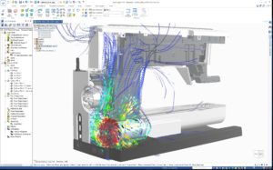
The latest release of SimScale, available shortly, will integrate Parasolid and HOOPS Exchange for a more convenient and seamless simulation workflow, while at the same time increasing simulation result accuracy—both in FEA and CFD.

“Our vision at SimScale is to enable every designer and engineer to take full advantage of engineering simulation—independent of budget, hardware and know-how. This includes seamless interoperability with the customer’s CAD system as well as fast, robust and accurate preparation of CAD data to achieve reliable simulation results quickly. Integrating Parasolid and HOOPS Exchange will help us achieve just that.” said David Heiny, CEO and co-founder of SimScale.

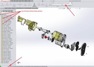
Parasolid is a 3D geometric modeling component for computer-aided design, manufacturing and engineering analysis (CAD/CAM/CAE) solutions, while HOOPS Exchange is a CAD translation software development kit (SDK).

“This latest implementation of Parasolid in a cloud-based application will enable engineers to simulate, test and modify 3D models using only a web browser,” says Jim Rusk, chief technology officer, Siemens PLM Software. “In selecting Parasolid, Simscale also obtains translation-free interoperability with hundreds of other applications that integrate Parasolid to design, edit and exchange high-precision 3D models based on the Parasolid XT data format.”

SimScale
www.simscale.com

Tech Soft 3D
www.techsoft3d.com

Filed Under: CAD Industry News, News, Siemens PLM, Simulation Software Tagged With: simscale

CAD modeling program lets you create on an iPad Pro

December 13, 2017 By Leslie Langnau Leave a Comment

Now you can develop CAD designs on any iPad Pro thanks to a CAD system developed by Shapr3D, a mobile 3D CAD modeling company, and Siemens PLM Software and Tech Soft 3D. The CAD system runs Siemens’ Parasolid software and HOOPS Exchange natively on iOS, and specifically the iPad Pro.

“The barrier to entry with CAD software is high in the case of traditional CAD tools that are complicated and expensive. We want to make 3D CAD modeling available for all creative professionals, and now, all you need is an iPad Pro, an Apple Pencil and some inspiration,” said István Csanady, Founder and CEO of Shapr3D. “We are creating 3D modeling for the 21st century, enabling 3D modeling anytime, anywhere in a new way that is much easier and much more affordable.”


The newest release of Shapr3D integrates Parasolid and HOOPS Exchange to allow solid modeling and data translation locally within the app. Siemens’ Parasolid is a leading 3D geometric modeling component, while HOOPS Exchange is a CAD translation software development kit (SDK). By integrating these two technologies with Shapr3D’s precision touch screen interface, engineering and design professionals now have the power of desktop modeling on a tablet, the iPad Pro.

“After years of research, we found that touch screens are not optimal for precise engineering. Detailed 3D CAD design on tablets only became a reality after Apple released the iPad Pro line in early 2016, which uses a pressure sensitive, active stylus. The key to success was to integrate the Apple Pencil’s pixel perfect precision and the touch-based user interface. We were the first company to do this successfully,” added Csanady.

“Finding a way to do professional-grade 3D modeling natively on a mobile app has been the something that so many in the industry have been striving for,” said Gavin Bridgeman, CTO at Tech Soft 3D. “The team at Shapr3D has taken mobile 3D CAD modeling to a new level, and the feedback we’ve seen from users so far is indicative of just how powerful this new app will be. We are thrilled to be a part of this pioneering journey to bring industrial 3D modeling and data conversion to mobile devices – a move that will have a lasting impact on the engineering world.”

“Siemens PLM Software has a proven track record of making Parasolid openly available to other software vendors, so that designers and engineers working in different domains can design, edit and share Parasolid models, regardless of their choice of application,” said Jim Rusk, CTO, Siemens PLM Software. “Working closely with Shapr3D accelerated our release of Parasolid on iOS, which has enabled us for the first time, to make Parasolid available to users and developers of apps for the iPad Pro.”

First launched in March 2016, Shapr3D is a direct modeling tool with an intuitive 3D modeling user interface on a tablet device. It is easy to learn and easy to use, but built with professionals in mind.

One of the big differences between Shapr3D and other mobile CAD tools is that everything runs locally on the iPad Pro. There is no pushing files or rendering jobs up to cloud, and it also runs offline without an internet connection. There is no cloud storage, all data is stored and secure on your iPad Pro. Shapr3D is compatible with all major CAD software and is ideal for 3D printing.

“While most of our users have been professionals such as product designers, engineers, architects, jewelry designers and 3D printing hobbyists, we also have users from MIT, Harvard, Stanford, Berkeley, Duke, Columbia, Cambridge, University of Tokyo, Singapore Polytechnic and many other schools worldwide,” added Csanady. “We see this as an opportunity to empower as many students as possible, all over the world, to fuel their creativity and design aspirations. To help them, we are offering the Educational license for free.”

The Basic version is free to all users. The PRO version of the software is free of charge for individual students, teachers and faculty members from any accredited educational institution. Getting the PRO version license only takes three easy steps after downloading the app to the iPad Pro.

Shapr3D
Shapr3D.com

Filed Under: News, Siemens PLM Tagged With: shapr3d

Siemens and IDS partner offer electromagnetic engineering design capabilities in Simcenter

September 28, 2017 By Leslie Langnau Leave a Comment

Siemens entered into a strategic partnership with Ingegneria Dei Sistemi (IDS), an independent engineering and systems technologies company based in Italy, to provide high-frequency electromagnetic (EM) engineering solutions to the market. As such, the Simcenter portfolio will have a more complete offering, with the additional ability to engineer the electromagnetic performance of systems with regard to antenna design and installation, EM Compatibility (EMC), EM Interference (EMI), EM hazards and more.

This strategic partnership fits into Siemens’ goal to address the engineering needs of smart systems with convergence of product lifecycle management (PLM) and electronic design automation (EDA) software. By further complementing solutions from Mentor, the partnership reinforces Siemens’ offerings in autonomous driving (AD) and the Internet of Things (IoT).

The performance of electronic devices and smart systems depends largely on electromagnetic behavior. With the increasing integration of electronics into everyday products and increased connection to IoT, engineers need a fast, accurate representation of how products will perform in real-life situations to ensure design success. This large increase of electronics, specifically wireless devices, creates a likelihood of EM interference and potential system malfunctions, but also allows the opportunity for new product functionalities if properly managed in the design stage.

Electro-Magnetic Compatibility (EMC) Analysis of the front part of an aircraft (Courtesy of Piaggio Aerospace & HIRF-SE Project)

In automotive, autonomous driving presents a higher stakes circumstance where reliability and safety require high-quality EM sensor behavior for obstacle detection and collision avoidance, both long and short range, but also V2X. IDS solutions provide realistic predictive engineering, on scalable virtual models ranging from individual sensors through full systems integrated into virtual cars. By integrating such highly physical EM radar and communication systems simulations into driving scenarios, car manufacturers will be able to increase the safety and performance of autonomous vehicles.

Detailed performance simulation in context of Vehicle to Vehicle communication.

Siemens PLM Software
www.siemens.com/plm

Filed Under: Siemens PLM Tagged With: Siemens PLM

TASS International acquisition propels Siemens to forefront of automated driving solutions engineering

September 5, 2017 By Leslie Langnau Leave a Comment

Bruce Jenkins, Ora Research

Siemens announced an agreement to acquire TASS International, a global provider of simulation software and related engineering and test services primarily to the automotive industry focused on autonomous driving, integrated safety, advanced driver assistance systems (ADAS) and tire modeling. Based in Helmond, The Netherlands, TASS has developed what Siemens terms “a rich family of solutions that will further strengthen Siemens’ product lifecycle management (PLM) software portfolio, and add to its position as the leading supplier of systems-driven product development offerings for the global automotive industry.” The combined offerings, Siemens says, will provide “a fully integrated solution to frontload verification and validation of automated driving systems.”

This move puts Siemens PLM Software squarely in the vanguard of the industry’s accelerating trend of deep investment in technology platforms for engineering modeling and simulation of autonomous and semi-autonomous vehicles, especially their onboard sensing and decision-making systems. See for example our VIRES acquisition by MSC Software accelerates Hexagon’s simulation portfolio and autonomous X strategy, and ESI Pro-SiVIC 2016 models how sensors perceive scenes and smart products make decisions.

TASS PreScan model of autonomous emergency braking system in Euro NCAP (European New Car Assessment Programme) test scenario.

“The automotive industry is a core focus for Siemens, and our acquisition of TASS International is another example of our commitment to offer a complete Digital Enterprise solutions portfolio, enabling automotive companies to realize their digital transformation and fully benefit from all opportunities of digitalization,” said Dr. Jan Mrosik, CEO of Siemens’ Digital Factory Division. “TASS International is a proven leader in both integrated safety and autonomous driving, two fields of engineering that are increasingly important for the industry. By combining its strengths with Siemens’ PLM offerings, we are able to respond even better to today’s challenges in the automotive industry.”

Goal: “Integrated toolchain for verification and validation of complex automotive functions” to benefit automotive industry and government organizations worldwide

With active safety and ADAS features increasingly becoming the norm in the automotive industry, Siemens observes, “the compelling trends of connected and autonomous driving vehicles set new requirements for virtual and physical validation and verification of automotive vehicles.”

TASS MADYMO human model.

“The Siemens PLM Software portfolio offers a significant opportunity for TASS International and its customers to accelerate the development of safety-critical applications in the field of automated and connected driving,” said TASS International CEO Jan van den Oetelaar. “Our engineering and test services will reach a larger audience through the extensive Siemens global footprint. The integration of TASS International into the Siemens organization is expected to create a stable long-term environment and allow access to a vast knowledge base. This can help to build an integrated toolchain for verification and validation of complex automotive functions that should benefit both the automotive industry as well as government organizations worldwide.”

Products: PreScan traffic scenario modeling, virtual validation of driving systems; MADYMO occupant safety modeling; Delft-Tyre tire modeling for vehicle dynamics/ride/handling simulations

TASS International is focused on automated driving solutions and integrated (active/passive) safety, primarily for the automotive industry. With its PreScan software, car manufacturers, suppliers and government agencies can simulate complex traffic scenarios and virtually validate automated driving solutions and advanced driver assistance systems. With its leading MADYMO software for occupant safety modeling, TASS International can simulate the impact of a car crash on the human body. TASS International’s Delft-Tyre software provides highly accurate tire models for vehicle dynamics and ride and handling simulations.

Tire model creation in TASS Delft-Tyre.

TASS International’s simulation software will be combined with Siemens’ Simcenter portfolio of advanced simulation offerings, and its electronic design automation (EDA) solutions from the recently acquired Mentor Graphics organization. See our Mentor Graphics acquisition positions Siemens to become mechatronics engineering powerhouse. The combination, says Siemens, “will provide a unique, fully integrated solution to frontload the verification and validation of ADAS and autonomous driving systems, providing Siemens with the world’s most complete systems-driven product development offering for autonomous vehicles.”

Siemens will acquire 100 percent of the share capital of TASS International and integrate the business into its PLM Software Business Unit, part of Siemens’ Digital Factory Division. TASS International has some 200 employees and annual revenue of €27 million. Financial terms were not disclosed. Closing is expected early this month.

TASS International

Simcenter

Siemens PLM Software

Euro NCAP

Filed Under: Siemens PLM Tagged With: Siemens PLM Software

Siemens unveils Integrated Software Engineering solution for automotive embedded software

July 31, 2017 By Leslie Langnau Leave a Comment

Bruce Jenkins, Ora Research

The first fruits of Siemens’ 2015 acquisition of application lifecycle management (ALM) tool developer Polarion came to bear in a new Integrated Software Engineering solution for the automotive industry intended to address critical product development challenges stemming from the explosive growth of embedded software in today’s increasingly smart, connected, self-aware and situationally aware vehicles. For background on the acquisition, see our ALM-PLM integration challenges and opportunities.

By integrating ALM software with product lifecycle management (PLM) software, Siemens’ aim is to deliver a solution to help automakers seamlessly manage the inherently different engineering lifecycles of electromechanical systems and of the software used to control them. Key benefits:

  • Unites ALM with PLM.
  • Integrates embedded software and physical systems development.
  • Improves automotive product quality, software robustness and traceability.
  • Quality improvement aims to significantly reduce software-related recalls.

The goal is to help automotive engineering organizations enhance software functionality and traceability, and at the same time improve overall product quality and reduce automotive recalls associated with embedded software. Siemens said this will be the first in a series of announcements about the family of Digital Enterprise Industry Solutions developed by Siemens’ PLM Software business.

“As cars get more sophisticated—with features like collision avoidance, automatic parallel parking, and the advent of self-driving, autonomous vehicles—the need for software to control these functions will continue to accelerate, resulting in increased challenges for product development,” said Siemens PLM Software vice president of automotive and transportation Dave Lauzun. “By integrating ALM and its ability to manage the embedded software development process with PLM’s capacity to manage physical systems, Siemens is providing a way for automotive companies to more rapidly, efficiently and accurately develop the robust and high-quality mechatronic systems that will power the future of transportation.”

Challenges of synchronizing ALM and PLM

Managing embedded software development in close synchronization with the development of physical systems is a big challenge for automotive companies, Siemens observes. Due to their respective natures, product engineering and software engineering follow inherently different development lifecycles. Software development is managed separately, and interface validation with hardware is done only at predefined checkpoints.

Most automotive programs are managed on a three- to five-year cycle, Siemens explains. They follow a gate-based development paradigm with strict checkpoints and certifications. Software development, on the other hand, is incredibly fast-paced, as it follows agile processes where collaboration and rapid innovation are key. Typically, development of mechanical, electrical and electronic systems is managed within product lifecycle management (PLM) tools, while software development is managed with application lifecycle management (ALM) tools. The challenge is to combine these two inherently different product development methodologies. Software and hardware engineers working on their respective ALM and PLM applications must be able to access information across all lifecycle-related processes.

Spiraling vehicle complexity “exposing deficiencies of current processes, tools and methods”

“In an era of smart-connected cars, the interactions between software and physical systems are increasingly becoming more complex, exposing deficiencies of current processes, tools and methods,” Siemens pointedly, and correctly, observes. “A Digital Twin of vehicle systems capable of representing the complete physical and digital behavior of today’s IoT-connected cars is necessary to realize innovations.”

The company says its Integrated Software Engineering solution for the automotive industry “finally moves embedded software development into its proper place as an integral part of the full product lifecycle. This move is essential for automotive companies to thrive in the face of rapidly changing technologies, providing a new level of agility in automotive product development.”

Over the next several months, Siemens PLM Software says it will be launching a series of announcements about its Digital Enterprise Industry Solutions aimed at addressing pressing business needs for a wide variety of industries.

Siemens Integrated Software Engineering solution: https://www.plm.automation.siemens.com/en/automotive-transportation/automotive-software-development/index.cfm

Filed Under: Siemens PLM Tagged With: Siemens PLM

Changes in CAD—what you need to know

June 26, 2017 By Leslie Langnau Leave a Comment

With the March release of Inventor 2018 and AutoCAD 2018, it’s a good time to review several of the recently released major CAD programs. Here’s a look at some of the biggest enhancements and key features of these programs.

Jean Thilmany, Contributing Editor

CAD packages are updated with the same regularity as other major software systems, often annually, with smaller releases to fix bugs or for minor updates happening throughout the year. Sometimes, the annual updates include major enhancements or completely new features. Other times, they include new subscription models, as is the case with Inventor, or offer new ways to access the software, such as through the cloud, which Solid Edge announced with its ST 9 version.

Autodesk Inventor

Here’s what designers will see in the latest version of Autodesk’s flagship mechanical design package:

Large-assembly design has also been made easier in Inventor 2018 from Autodesk. The capability to pan and zoom in on both 3D and 2D designs is improved in this version. The image shows an example of a machine design by equipment-maker Mastenbroek using Inventor.

The big news with the March release of Autodesk Inventor is its subscription-based plan. Users can subscribe for $235 per month. Or, they can choose to pay upfront at $1,890 for one year, $3,590 for two years, and $5,105 for three years.

These type of short-term subscription plans are good for companies that may bring on extra designers, and need more software seats, or during certain times of the year, or for companies that have landed a large project and need more help carrying it out, says Luke Mihelcic, an Autodesk product marketing manager.

Autodesk also has plans to roll out new functions for Inventor every few months rather than within one big, annual update. That is to say, Inventor will see new versions, or major releases, followed by incremental updates that build upon them, Mihelcic adds.

–Model-based definition

This year’s annual update includes model-based design (MBD) tools that users can use to annotate models with product manufacturing information (PMI) like tolerances, dimensions, and manufacturing notes. The tools help projects move from the modeling to the manufacturing stage faster than without the notes, Mihelcic says.

While annotating 3D models already saves time formerly spent creating 2D manufacturing drawings, this new release saves engineers who design in Inventor even more time because they don’t need a special authoring application for 3D annotation. Many engineers who use MBD to annotate models with 3D PMI still have to learn the separate, special application.

–Collaboration tools and ease of use

Inventor has also upped the tool’s interoperability, Mihelcic says. With the 2018 version, users can output 3D PDF files so design information can be shared with others—whether they’re part of the company or not–including manufacturers, customers, suppliers, and marketing managers.

Also in Inventor 2018, the “measure” tool has been simplified and improved to make it easier to use, and bill of materials and parts list sort orders have been made easier to organize because they’re now based on the commands users add themselves, he says.

AutoCAD 2018

The other big system from Autodesk, AutoCAD turns 35 this year. The CAD software and its cousin, AutoCAD LT–which stands for “light” and doesn’t include the full roster of features seen in the main version–also saw a March update, to version 2018, says Heidi Hewett, AutoCAD technical marketing manager.

Autodesk released its AutoCAD 2018 design tool in March.

The newest version is built on a modern code base, which means it runs smoother and faster on current hardware than past versions. In fact, AutoCAD 2018 now supports 4K high-resolution monitors and screens. A 4K display is comprised of 3,840 or higher pixels of horizontal resolution and 2,160 pixels of vertical resolution.

–DWG 2018

The updated CAD system also includes the 2018 DWG (short for drawing) file format, which is the data-file-format AutoCAD uses to create and save designs. This format will improve the efficiency of open and save operations, especially for drawings that contain many annotative objects and viewports, according to Hewett.

This is the first DWG update since 2013. That’s important to know because, while designs created with AutoCAD 2018 will be saved to the 2018 DWG file format, older versions of AutoCAD cannot read the 2018 format. Designers sharing with users on systems that don’t support the 2018 DWG format will need to save their files using an older version of DWG, likely the 2013 version.

–Navigation and Reference Improvements

Version 2018 also introduces tools to fix broken paths for externally referenced files, which helps reduce problems created by broken reference paths and saves the time spent on relinking paths. The upgrade allows users to replace external paths that have one or more missing references with a new path, according to Hewett.

The workflow for creating references is improved with this version. A relative path is automatically assigned to all new, external references.

Users can still choose to assign references as “full path” as was done automatically in previous versions. They can also specify a relative path before saving their drawing. In the past, they couldn’t specify a relative path until they were saving their drawings.

AutoCAD LT won’t see the 3D navigation performance enhancements included in AutoCAD 2018, which Autodesk said offers improvements when using zoom, pan and 3D orbit operations. For example, many larger drawings will no longer degrade as users navigate around the model, the company says. The performance for manipulating 3D models is approaching that of 2D drawings, Hewett adds.

–CAD Viewer update

Autodesk recently re-released the Design Review CAD viewer, which the CAD maker hadn’t updated since the 2013 version. The CAD viewer software lets users view, mark up, print, and track changes to 2D and 3D files for free—even if they don’t own or use AutoCAD. It works with a variety of file formats, including: DWF, DWFx, DWG, and DXF, Adobe PDF, as well as image file types such as.bmp, .jpg, .gif, .png, .tif, .cal and a host of others. The DXF, or drawing exchange format, from Autodesk allows data to be exchanged and read between AutoCAD and other programs.

Solid Edge

This CAD system is Siemens PLM’s main design and engineering offering, with release ST10 soon to come. ST stands for synchronous technology, the method Solid Edge uses for modeling rather than the usual constraint-driven or history-tree modeling. It gives designers the ability to edit models directly rather than making the changes within hierarchical and dependent feature trees, according to Siemens.

Built in data-manage tools included within Solid Edge ST9 are updated with the ST10 release.

–Manage information

Also, new built-in data management tools help manage revisions. In a new “revisions” dialogue box, users can see the entire revision history of a part. They can also comment on any revision in the revision tree and ask whether newer versions of a part are available.

–Sheet metal design and more

Users can design sheet metal parts with Solid Edge ST10 and can edit those parts directly, even if they’re bent. They can also reposition features on the parts, resize them, and change their form without having to go back through the feature tree to correct design errors.

Siemens PLM continues to integrate new capabilities into its Solid Edge CAD system through recent acquisitions including Polarion, for development of software embedded within products, and CD-adapco, for design simulation.

–Additional features

A design manager feature has been added to simplify detecting and replacing duplicate files. After launching the tool, users can see if any of the parts in an assembly have geometric matches with different names and replace them with the preferred part. They’re also able to see tell if a part has a drawing, making it easier to determine the value of one component over another.

The automatic routing path feature in ST10 means users can create routing paths automatically between points within an assembly, part, or sheet-metal design. In earlier versions of the tool, they needed to create routing paths manually. This is a boon for users who design pipelines or create designs that include wiring or hoses, for example, notes a spokesman at Siemens.

Solid Edge ST10 will be the last Solid Edge release to support Windows 7.

SolidWorks

SolidWorks 2017, released earlier this year, offers support for virtual and augmented reality devices such as HTC Vive, Oculus, Google Cardboard, and Samsung devices.

Large assembly capabilities have been improved in SolidWorks 2017, which was released in the fall of 2016 and is the latest version of the system from Dassault Systemes.

This version includes a new user interface, though the change isn’t as dramatic as seen in the previous release. The update now makes the order of configurations sortable, rather than existing only in the order they were created. Also, shortcut menus are streamlined and standardized.

–Interconnection

Users can also open proprietary 3D CAD data in SolidWorks 2017. Systems supported include Creo, CATIA V5, Solid Edge, NX, and Inventor. Associativity is maintained with the original file, meaning updates made within supported systems are automatically reflected in the SolidWorks file.

–Other features

The CAD maker has also expanded capabilities for model-based definition. With this version, users can compare geometry and 3D product and manufacturing information between two revisions, and attached multiple files to a 3D PDF to create technical data packages.

The company’s “visualize boost” feature makes for faster rendering speeds.

New features include a reliability tab that provides access to information such as how the previous session ended and the version of SolidWorks running.

The upgrade also introduces a new feature called “offset on surface,” which allows users to use existing 3D edge and face entities to create new sketches.

Other Updates

 Of course a number of other CAD packages such as TurboCad Deluxe 2017 and NX, also from Siemens PLM, have seen recent updates as well. And we expect to see new features included in future Creo Parametric (formerly Pro/e) versions. In CAD software, as in life, nothing stays the same forever—or even for very long.

Autodesk
Autodesk.com

Siemens PLM
plm.automation.siemens.com

SolidWorks
solidworks.com

Filed Under: 3D CAD Package Tips, Autodesk, Featured, Siemens PLM, SolidWorks

Solid Edge ST10 offers robust enhancements for design, simulation and collaboration

May 8, 2017 By Leslie Langnau Leave a Comment

The latest release of Siemens’ Solid Edge software (Solid Edge ST10) brings every aspect of product development to the next level with new design technology, enhanced fluid flow and heat transfer analysis and cloud-based collaboration tools. Improved publishing tools enable the creation of interactive technical documents and the ability to share designs in the cloud.

Solid Edge ST10 now makes it much easier to optimize parts for additive manufacturing (AM) and obtain quotes, material selection and delivery schedules from AM service providers. Newly integrated topology optimization technology, combined with Siemens’ exclusive Convergent Modeling technology, enables designers to dramatically improve product design efficiency and streamlines the ability to work with imported geometry.

“We import many 3D models for components like lamps and cushions in a faceted format,” said Ricardo Espinosa, R&D Engineering Manager at Kimball International. “The new Convergent Modeling technology that underlies Solid Edge ST10 will enable us to work faster and more flexibly with this data.”

Expanding beyond traditional CAD capabilities, Solid Edge ST10 offers a portfolio of tools to improve product development and design. New topology optimization technology, a subset of automated generative design, quickly optimizes the strength to weight ratio of individual part designs. Convergent Modeling simplifies the ability to work with geometry consisting of a combination of facets, surfaces, and solids – such as those created by importing third-party CAD files or through topology optimization. New simulation capabilities such as fully-integrated fluid flow analysis eliminate the need to transfer data between different applications, giving designers the ability to achieve accurate and fast fluid flow and heat transfer analysis directly in Solid Edge.

Enhancements to integrated computer-aided manufacturing (CAM) enables efficient programming of CNC machine tools, and the ability to define complex sheet metal components, optimized for manufacturing. New additive manufacturing tools enable users to 3D print parts in house or access a network of additive manufacturing services, optimizing material selection and delivery.

Solid Edge ST10 also includes enriched publication features to quickly create detailed illustrations of designs. Publishing interactive digital documents help communicate the correct manufacturing process and maintenance procedures for products. These documents are associative to the original design information, enabling rapid updates to the documentation when the design changes. New enhancements to built-in Solid Edge data management and improved integration with Siemens’ Teamcenter software delivers scalable product data management to help companies of all sizes become digital enterprises. Component classification and off-line working are now supported for Solid Edge using the embedded Teamcenter integration.

The Solid Edge portal will offer a cloud-based solution to collaborate with other users, suppliers and customers, simplifying communication in product development cycles. Offering a new way to work cooperatively, the portal allows users to upload and manage files in cloud-based folders, with multi-platform browser-based viewing of Solid Edge and many other popular CAD applications.

“Digitalization is leveling the playing field, providing unlimited opportunities for small-to medium-sized businesses to disrupt industry,” said John Miller, Senior Vice President and General Manager at Siemens PLM Software. “The release of Solid Edge ST10 provides a portfolio of next generation product development tools that will enable our manufacturing customers to fully collaborate in the digital economy.”

Solid Edge ST10 is scheduled to ship in summer 2017.

Siemens PLM Software
www.siemens.com/plm/st10.

Filed Under: Siemens PLM Tagged With: Siemens PLM Software

Siemens closes Mentor Graphics acquisition

March 30, 2017 By Leslie Langnau Leave a Comment

With the recent closing of its acquisition of electronic design automation (EDA) software leader, Mentor Graphics Corporation (Mentor), Siemens sets out to underscore what it envisions for both Electronic Systems and Integrated Circuit (IC) design tools.

Mentor is now part of Siemens’ product lifecycle management (PLM) software business, making the combined organization the world’s leading supplier of industrial software used for product design, simulation, verification, testing and manufacturing. As today’s products – from smart phones and household appliances, to automobiles, aircraft and machinery – continue to increase the use of sophisticated embedded electronics, Siemens has positioned itself to provide a seamless and comprehensive software solution to the companies that develop these products.

 “The entire suite of EDA offerings from Mentor are critically important to our vision of growing our customer base and delivering the world’s most comprehensive portfolio of software solutions to build the Digital Enterprise,” said Tony Hemmelgarn, President and CEO, Siemens PLM Software. “Software tools such as Electrical & Wire Harness Design and Electronic Systems Design, perfectly complement our existing solutions, while tools for IC Design, Verification, Test and Manufacturing expand our offerings and expertise into adjacent segments to bring value to a new set of clients.

“Siemens is now the leading company providing a complete set of integrated software solutions across the entire value chain. We are proud to welcome the outstanding Mentor team and all of their excellent technology into our organization.”

With approximately $10 billion in investments in multiple software companies since 2007, Siemens has made a significant push into the software space with acquisitions including UGS, LMS, Camstar, Polarion, and CD-adapco. Now, with the acquisition of Mentor, Siemens will continue its proven track record of effectively merging new organizations and technology into the industry’s leading Digital Enterprise Suite. This comprehensive suite helps customers create the industry’s most holistic and precise digital twins of their products and production lines.

“Joining the Siemens family presents tremendous opportunity, not only for the Mentor Graphics team, but also for existing, new and future customers,” said Walden C. Rhines, CEO, Mentor Graphics. “Siemens’ desire to leverage all of Mentor’s technologies – from our IC offerings to our systems solutions – was an important part of this transaction. We are proud to become part of an organization with such an excellent reputation and successful track record over the years.”

Siemens PLM Software
www.siemens.com/plm

Filed Under: Siemens PLM Tagged With: Siemens PLM Software

A look at Parasolid version 29.1

March 16, 2017 By Leslie Langnau Leave a Comment

Parasolid v29.1 from Siemens PLM delivers enhancements to both B-rep modeling and Convergent Modeling technology. B-rep enhancements focus on high-value workflow automation enabling application developers to deliver functionality more effectively. Convergent Modeling enhancements focus on working with imported facet data and the architectural foundations to support fully integrated Convergent Modeling in future where all Parasolid operations will support models containing arbitrary combinations of classic B-rep geometry and facet B-rep geometry.

Modeling

Enhancements have been made to tapering and sweeping to remove potential workflow bottlenecks to deliver successful operations on more complex configurations and provide better diagnostic information when an operation is not possible on a specific configuration:

  • Improved quality surfaces are produced when mitering tangent to faces in a body and provide miter-specific failure information if a body taper fails during a mitering operation.
  • Added support for tapering a body with a negative taper angle.
  • Added option to use a law curve to untwist a twisted sweep along a closed path to ensure alignment at start and end of sweep.
Untwisting a rotation in the path to ensure a successful sweep along the 3D closed path

Blending

Several enhancements have been made to handle operations on complex configurations to improve the success rate of automated workflows, removing the need for application developers to handle these case in their code:

  • Optimized results when blends of very similar but different radius interact.
  • Improved robustness and surface quality when blending on the inside of tightly curved surfaces, and when repairing self-intersecting blend surfaces.
  • Improved handling of partial notches when deleting notch blends.
Improved quality when blending on the inside of tightly curved surfaces


Convergent Modeling

In addition to extensive, on-going architectural work to support full Convergent Modeling functionality, a number of enhancements have been delivered to help application developers work with facet data not created by Parasolid:

  • Added functionality to detect and fix common facet mesh issues such as: corrupt meshes, non-manifold meshes, mesh vertex with bad normal, degenerate mesh facet, self-intersecting meshes, meshes with slits, disjoint meshes.
  • Added functions to enquire mesh data include: ask the convexity of an edge on a mesh, find sharp mesh vertices in a mesh, ask the normal of a mesh vertex.
  • Added option to request principal directions and curvatures when faceting both classic and facet b-rep bodies.
Facet data imported into Parasolid, such as STL, may require analysis and repair


Siemens PLM
community.plm.automation.siemens.com

Filed Under: Siemens PLM Tagged With: Siemens PLM Software

Siemens PLM Software releases version 5.0 of Kineo software

March 2, 2017 By Leslie Langnau Leave a Comment

Version 5.0 of  Kineo software components is for path planning, collision detection and cable simulation. It includes:

  • Kineo Flexible Cables – for modeling deformable cables during motion simulation
  • KineoWorks Interact – a graphical user interface for developing Kineo-enabled applications quickly and easily
  • KineoWorks and Kineo Collision Detector – a capabilities and implementation enhancements

Kineo Flexible Cables

This software component has been developed for applications in robotics. The cables that power articulated robot systems are prone to failure from repeated stress and collisions in the operating environment.  Kineo Flexible Cables enables you to model collision-free cable behavior in motion simulation applications.

KineoWorks Interact

This software component enables users to simulate cable path planning and collision detection.  It helps users customize a rich graphical user interface for developing complex applications.

KineoWorks Interact is for OEMs and System Integrators with limited software development resources, who recognize the value in developing state-of-the-art software solutions for robot simulation, digital mock-up, accessibility studies and related applications.

KineoWorks and Kineo Collision Detector

KineoWorks offers an integrated tool for computing an envelope around static and moving parts. In the case of static parts or assemblies, this “wrapping” capability generates light-weight data representations. User-defined levels of tessellation enable users to represent space allocation, without exposing confidential product detail. In the case of moving parts, a comprehensive “swept volume” helps users determine space allocation for moving parts.

Kineo Collision Detector offers direct support for collision and clearance analysis on point clouds, with no need to convert the point cloud data.

Both components also benefit from a new C# interface, support Visual Studio 2015 as well as compatibility with KineoWorks Interact product for developing rich applications quickly and easily.

Siemens PLM Software
www.plm.automation.siemens.com

Filed Under: Siemens PLM Tagged With: Siemens PLM Software

  • « Go to Previous Page
  • Go to page 1
  • Go to page 2
  • Go to page 3
  • Go to page 4
  • Interim pages omitted …
  • Go to page 8
  • Go to Next Page »

Primary Sidebar

3D CAD NEWSLETTERS

MakePartsFast

Follow us on Twitter

Tweets by 3DCADWorld

Footer

3D CAD World logo

DESIGN WORLD NETWORK

Design World Online
The Robot Report
Coupling Tips
Motion Control Tips
Linear Motion Tips
Bearing Tips

3D CAD WORLD

  • Subscribe to our newsletter
  • Advertise with us
  • Contact us
Follow us on Twitter Add us on Facebook Add us on LinkedIn Add us on Instagram Add us on YouTube

3D CAD World - Copyright © 2022 · WTWH Media LLC and its licensors. All rights reserved.
The material on this site may not be reproduced, distributed, transmitted, cached or otherwise used, except with the prior written permission of WTWH Media.

Privacy Policy