Dassault Systèmes announced at CES its Global Entrepreneur Program to accelerate the development of breakthrough innovations by startups, entrepreneurs and makers. The program, which leverages Dassault Systèmes’ 3DEXPERIENCE platform, applications, expertise, and community of mentors and services, delivers a full portfolio of tailored solutions and different types of engagement to accompany innovators at every step of their development, from seed to late stage.
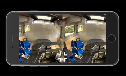
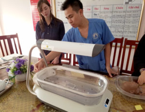
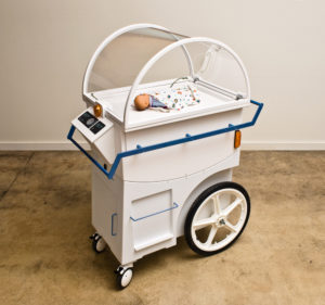
More than 1,000 startups, entrepreneurs and makers have already embarked with Dassault Systèmes on digitally developing real-world products and experiences. With the Global Entrepreneur Program, they can use virtual worlds, collaboration, collective intelligence and communities to facilitate innovation, creativity, and to bring ideas to fruition. Innovators can advance projects integrating internet of things and other technologies, design and test products, access online prototyping services using the latest 3D printing methods, and share knowledge and knowhow with a qualified network of professionals, experts and peers from many industries.
Startups have different needs at each phase of their lifecycle. A one-size-fits-all technological, mentoring and marketing approach falls short of providing the diverse levels of support required to help them get products to market faster while, in parallel, addressing business challenges inherent to the startup world such as funding, staffing, IT infrastructure or sales.
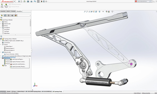
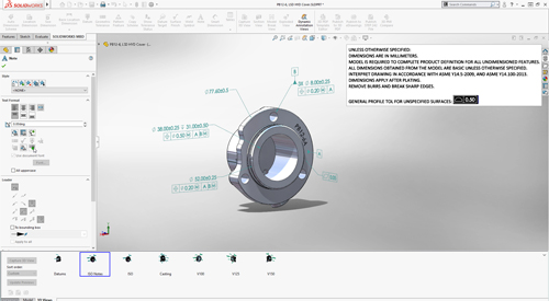
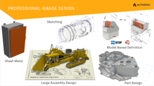
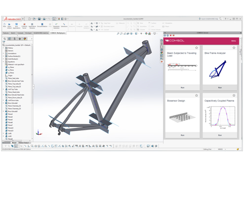
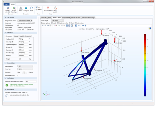
The Global Entrepreneur Program’s tracks include design applications and training from SOLIDWORKS for Entrepreneurs for projects focused on mechanical innovation, as well as immersive acceleration in the 3DEXPERIENCE Lab for disruptive startups transforming society that require mentoring, prototyping and marketing support through a network of incubator, accelerator and Fab lab partners across the U.S. and Europe.
The Global Entrepreneur Program also includes the cloud-based 3DEXPERIENCE platform, community management, support and services that bring speed, agility, flexibility, experimentation and collaboration to projects that require more than just a new product engineering activity.
“Entrepreneurs have told us that they value the social community of an incubator above all else, and we listened,” said Frédéric Vacher, Director, Corporate Strategy Innovation, Dassault Systèmes. “Dassault Systèmes loves startups, and our Global Entrepreneur Program supports their innovation processes by providing cloud applications and online communities and services, whatever their industry, product, needs or maturity level. Gone are the days when only large companies had the myriad of skills, resources and capabilities to yield breakthroughs. We are a catalyst and enabler for large companies and startups alike to create concepts, bring virtual and real worlds together, and empower a renaissance of innovation.”
Dassault Systèmes
www.3ds.com