• Skip to primary navigation
  • Skip to main content
  • Skip to primary sidebar
  • Skip to footer

3D CAD World

Over 50,000 3D CAD Tips & Tutorials. 3D CAD News by applications and CAD industry news.

  • 3D CAD Package Tips
    • Alibre
    • Autodesk
    • Catia
    • Creo
    • Inventor
    • Onshape
    • Pro/Engineer
    • Siemens PLM
    • SolidWorks
    • SpaceClaim
  • CAD Hardware
  • CAD Industry News
    • Company News
      • Autodesk News
      • Catia News & Events
      • PTC News
      • Siemens PLM & Events
      • SolidWorks News & Events
      • SpaceClaim News
    • Rapid Prototyping
    • Simulation Software
  • Prototype Parts
  • User Forums
    • MCAD Central
    • 3D CAD Forums
    • Engineering Exchange
  • CAD Resources
    • 3D CAD Models
  • Videos

SolidWorks

What is saving 90% in engineering time worth?

April 17, 2012 By Evan Yares Leave a Comment

Engineer-to-order (ETO) software has been around for a long time, with roots reaching back to knowledge management systems developed in the 1980s.
The biggest reason more companies don’t use engineer-to-order software is that the front-end configuration, to set up an ETO system, has often been too much work, requiring lots of training and expensive consultants.

Tacton makes a SolidWorks-based tool for ETO: TactonWorks. They just issued a press release reporting that one of their customers, Mitsubishi Heavy Industries, has seen a 90% time savings in engineering work for custom orders. This after only having used the software for about 3 months.

The press release gives no clue as to how much work it was to configure TactonWorks with their SolidWorks models. While I suspect it was fairly easy, the fact that they’re saving 90% time within 3 months of starting suggests that it wasn’t all that hard, and that buying TactonWorks was a home-run for Mitsubishi.

Here is the press release:

Mitsubishi Heavy Industries Compressor (MCO) Chooses TactonWorks for Customization of Large Scale Compressors and Turbines

Stockholm, Sweden – April 16, 2012- Mitsubishi Heavy Industries Compressor Corporation, (MCO) began using TactonWorks in 2011 and has already seen drastic time savings for detailed engineering work of up to 90% per quote.

MCO, a 100% owned subsidiary of Mitsubishi Heavy Industries, Ldt. (MHI) is a leading global supplier of large scale compressors and turbines used at petrochemical plants, natural gas processing plants, LNG Plants, FPSD, etc. in more than 60 countries.

TactonWorks, an add-in to SolidWorks, is Tacton’s tool for Design Automation. It automates the customization of complex products, which helps you save time and money. It also ensures correctly updated models and drawings.

Not long ago, MCO saw a need to automate the customization of their products in order to reduce delivery time and engineering costs. Their reseller, Hiroshima Daia Systems HDS learned about Tacton and TactonWorks at SolidWorks World Japan in 2010. MCO implemented TactonWorks for the first section of their assembly three months ago and have already experienced detailed design time savings of approximately 90% per customization.

“We are amazed at the amount of time we’ve saved since starting to use TactonWorks—and this after implementing it in only one part of our product assembly. We really believe in this solution and are eager to start using it for our other models as well”, says Mr.Yasuhiko Omi, Director of Plant Engineering Division at Technology Management Center, MCO.

MCO plans to continue to implement TactonWorks for the other parts of their assembly with a final goal of having the complete assembly implemented.

“We are very happy to see a customer get such fantastic return after using our solution for only a short period of time. We look forward to seeing how much more time they will save in the coming phases of the project”, says Christer Wallberg, CEO Tacton Systems.

The sale was made together with Tacton’s Japanese partners, Hiroshima Daia Systems (HDS), who implemented the solution and Kozo Keikaku Engineering (KKE), who sold the software licenses.

For more information contact:

Christer Wallberg, CEO, Tacton Systems AB
Telephone: +46 8 690 07 50
E-mail: christer.wallberg@tacton.com

About Mitsubishi Heavy Industries

Mitsubishi Heavy Industries Compressor Corporation (MCO) is a wholly-owned subsidiary of Mitsubishi Heavy Industries, Ltd. (MHI) specializing in the compressor business. We were formed by integrating the compressor business of the Industrial Machinery Business, Technology & Solutions Division with MHI Turbo-Techno Co., Ltd. (MTT, a company which is responsible for after-sales services.

About Tacton Systems

Tacton Systems is the world leader in advanced configuration. Tacton develops and sells embeddable software for sales and design configuration. This software simplifies the sale of customized, complex products offline as well as online. Tacton’s solutions integrate easily with surrounding systems and have standard integrations for many leading e-commerce, ERP, CRM, PDM, PLM, and CAD systems. Customers currently using Tacton’s solutions include GE, Siemens, Tetra Pak, ABB, Scania, Toshiba, Aker, and Alfa Laval. www.tacton.com.


Filed Under: Evan Yares, Featured, News, SolidWorks Tagged With: Mitsubishi Heavy Industries, SolidWorks, Tacton, TactonWorks

SolidWorks Plastics

April 5, 2012 By Evan Yares 3 Comments

Mr. McGuire: “I want to say one word to you. Just one word.”

Benjamin: “Yes, sir.”

Mr. McGuire: “Are you listening?”

Benjamin: “Yes, I am.”

Mr. McGuire: “Plastics.”

– The Graduate, 1967


Dassault Systemes SolidWorks Corp this week announced a new product: SolidWork Plastics.

Actually, it’s not strictly new, and it’s not just one product. SolidWorks Plastics was developed and originally sold by Simpoe, a provider of plastics injection molding simulation software. Dassault entered into an agreement whereby SolidWorks will now sell the software under their banner.

There are two versions of SolidWorks Plastics. The Professional version (US$4,995.00) is for people who design plastic injection molded parts. The Premium version (US$14,995.00) is for mold designers.

If you’ve been using SolidWorks for a few years, you might remember that the 2007 version came with MoldflowXpress, a limited function molding simulation tool that included a generic materials database, part-only analysis, single gate location, and a go/no go result, showing whether a part would fill. MoldflowXpress was what you might call a “good enough to be useful, not good enough to take sales from our more expensive products” tool. Still, it was pretty useful, and nicely integrated into SolidWorks. It became unavailable about the same time SolidWorks’ arch-competitor Autodesk purchased Moldflow. (Imagine that!)

After MoldflowXpress went away, Simpoe was one of the companies that stepped up to the plate, to offer a “gold” partner product for plastics simulation running embedded in SolidWorks.

I’m guessing that users were happy enough with the Simpoe products that Dassault decided to bring them into the fold.

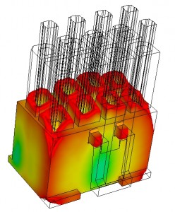
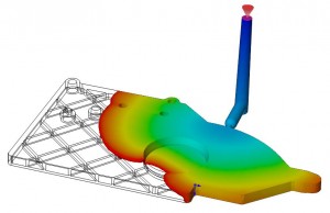
SolidWorks Plastics Professional is quite a bit more capable than MoldflowXpress ever was. It allows parts designers to verify uniform wall thickness (a fundamental best practice of plastics part design), optimize the thickness of features such as reinforcing ribs to avoid sink marks, and predict (and either minimize or eliminate) weld lines. It includes a material database with around 5,000 grades of commercial plastic. It has a very useful set of capabilities for people who design plastic injection molded parts. (And SolidWorks is probably the leading CAD tool for this purpose.) The important thing about SolidWorks Plastics Professional is that it lets parts designers verify manufacturability early in the design process, long before cutting any tool steel. It’s not trivially inexpensive, but compared to the cost of a few trashed molds it’s a bargain.

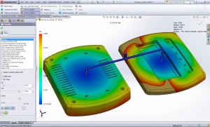
SolidWorks Plastics Premium is for mold designers. It’s a big-time full-function mold analysis tool, supporting analysis of single-cavity, multi-cavity and family mold layouts, runner balance analysis, and providing a wide range of report plot types for identifying and rectifying problems. It comes with automated report generation capabilities, for sharing results with others. A significant benefit of SolidWorks Plastics Premium, when compared to standalone analysis solutions, is that runs embedded inside of SolidWorks, and uses familiar workflows. Its learning curve should be comparatively easy for experienced SolidWorks users. It should go without saying (but probably doesn’t) that learning curve and usability are exceedingly important, even for people who are domain experts.

While SolidWorks Plastics isn’t technically an entirely new product, now that it’s part of the SolidWorks family, it’ll probably get more attention from resellers, and more awareness among users.  All told, a good thing.

DS SolidWorks Corp. www.solidworks.com/sw/products/plastics-injection-molding.htm

Filed Under: Evan Yares, Featured, Simulation Software, SolidWorks, SolidWorks News & Events Tagged With: Dassault Systemes, Moldflow, Plastics, SolidWorks

Autodesk provides real-time DFM for plastic part design

April 3, 2012 By Evan Yares 1 Comment

There’s a lot of benefit to be had by doing manufacturability analysis (DFM, Design for Manufacturing) early in the design process, rather than waiting until later, when design changes are far more expensive.

A couple of years ago, Autodesk Labs previewed a product, Project Krypton, which ran inside of 3D CAD programs (including Autodesk Inventor, DS SolidWorks, and PTC Pro/E), and gave real-time feedback on manufacturability, cost, and sustainability of plastic injection molded parts.


Project Krypton has now reappeared, in commercial form, as Autodesk Simulation DFM (Design For Manufacturing.) It works as a plug-in, running in a number of versions of Inventor, Inventor LT, Wildfire, Creo, and SolidWorks. It is available as a subscription benefit for Autodesk Simulation Moldflow Adviser 2013 subscribers, or as a stand-alone product, at US$2,000 for a license to run on any of the supported CAD platforms.

It’s reasonable to argue that engineers who are designing plastic parts should know enough to be able to recognize manufacturability, cost, or sustainability problems. And, if they don’t, they should take the time to learn (for example, by taking a few hours to read any of the many freely available books on the subject, such as General Design Principles for DuPont Engineering Polymers.) Even though that argument is reasonable, it doesn’t recognize human nature. People, even engineers who should know better, don’t always take the time to “read the manual.” Often, it makes sense to build the “manual” into the tools that engineers use every day. Simulation DFM does that, and quite a bit more.

For inexperienced designers, Simulation DFM provides quick feedback to help them avoid rookie mistakes. It’s sort of like an “idiot light” on a car’s dash, that warns you when something is wrong. And while old-hands might say they prefer gauges to idiot lights, experience has shown that idiot lights are useful to experts (even F1 drivers and fighter pilots) for catching their attention, and getting them to actually look at the gauges.
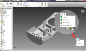
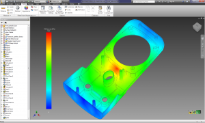
Simulation DFM doesn’t require that users have any background in molding simulation. It uses “green is good, yellow is not so good, and red is bad” indicators to identify potential manufacturing, cost and sustainability issues, showing the source and location of the problem. Any issues that pop-up can be expanded upon, to provide more detail on the exact source of the problem, even showing, for example, mold filling analyses.  The software requires no additional training, and doesn’t require much user input.

The open question with Simulation DFM is “how good is it?” Since it’s based on the Autodesk Moldflow simulation engine, it should be quite good, even for relatively complex parts (though it doesn’t support multi-body parts.) Yet, even if its capabilities were modest, it would still be of value, in either helping beginning designers to learn good design practice, or helping old-hands catch mistakes they might have otherwise missed.

As an engineer, I’ve long had the habit of using the “anything I can see” test to evaluate the usefulness of software. I look around the room, looking at anything I see, and ask myself “would this software have helped the engineers who designed these things?” In this case, as I sit in my office, I can see at least 20 items (without even turning to look behind me), each with multiple injection molded parts, that would have been quicker, easier, and less-expensive to design, had their engineers had access to up-front DFM software, such as Autodesk Simulation DFM.

The most significant benefit of Autodesk Simulation DFM comes not from its detailed capabilities, but rather from its clean integration into the design workflow. A user need not press a button, or take any specific action when designing a plastic part to benefit from it. All they need to do is notice, as they design, whether the software has picked up any obvious red-flags.

That Autodesk decided to make Simulation DFM available for Pro/E, Creo, and SolidWorks (as well as Inventor) shows that rational minds sometimes do prevail: There are untold thousands of PTC and SolidWorks customers who design plastic injection molded parts, and who are unlikely to switch primary CAD tools any time soon. The challenge Autodesk is going to face is in getting Simulation DFM in front of those users (since PTC and SolidWorks sales reps and dealers are not likely to recommend it.) Maybe not so much of a challenge: Many of Autodesk’s existing Moldflow customers are Pro/E and SolidWorks users.

There’s a certain charm to software that does something of great value, but does not impose any extra demands on its users. Autodesk Simulation DFM looks like it may be that kind of product.

Autodesk www.autodesk.com

Autodesk SimSquad simsquad@autodesk.com

Filed Under: Autodesk, Autodesk News, Creo, Evan Yares, Featured, Inventor, News, Pro/Engineer, Simulation Software, SolidWorks Tagged With: Autodesk, CAE, Creo, DFM, Inventor, Moldflow, Pro/E, simulation, SolidWorks

SolidWorks V6 is not SolidWorks

February 22, 2012 By Evan Yares 12 Comments

Two years ago, at SolidWorks World (the show) SolidWorks (the company) showed what appeared to be the next generation of SolidWorks (the software): SolidWorks V6 (also software.)

SolidWorks (the company) got major flak from bloggers concerned that SolidWorks V6 (the software) would replace SolidWorks (the software.)

This year, at SolidWorks World (the show), Dassault Systèmes SolidWorks (as the company is now known) didn’t talk much about SolidWorks V6 (the product), other than to say that they’d talk about it in 2013.

Now that we’ve got that all clear, let’s talk about what matters: SolidWorks V6 is confusing branding. It confuses not only users, but even pundits who write about CAD software.

My understanding, after talking to company representatives at SolidWorks World, is that SolidWorks V6 is the name for not just one product, but a future series of products. Those products may incorporate some existing SolidWorks technology, but they’ll be based largely upon CATIA and ENOVIA V6 technology. Because they’ll use the CGM modeling kernel (which was originally written for CATIA V5), they’ll likely be more compatible with CATIA than with today’s SolidWorks.

It makes sense that Dassault Systèmes would want to leverage the strength of the SolidWorks brand for this upcoming series of products. The SolidWorks brand is one of the strongest in the MCAD world. If SolidWorks V6 were actually based on, and entirely compatible with, SolidWorks—the name might fit. But it’s not, and it doesn’t.

The SolidWorks V6 name creates unnecessary fear, uncertainty, and doubt among SolidWorks users who are concerned that they’ll be forced to transition from a CAD program they know and (sometimes) love to this new technology, whether they want to or not.

What’s particularly unfortunate is that, if Dassault Systèmes had originally used a code name for the technology instead of calling it SolidWorks V6, they never would have created this whirlwind of FUD among their users. People might have seen it as just what it is: A really interesting future product, that they might want to add to their portfolio of CAD tools some day (when it’s ready.)

The bottom line is that the new technology called SolidWorks V6 isn’t SolidWorks, and won’t replace SolidWorks. According to Fielder Hiss, SolidWorks VP of Product Management, the development team working on SolidWorks 2013 is even larger than the teams that worked on previous versions.

The real SolidWorks—the CAD program now used by about 1.7 million people—is going to be around for a long time.

Filed Under: Evan Yares, Featured, SolidWorks, SolidWorks News & Events Tagged With: Catia, Dassault Systemes, ENOVIA, Evan Yares, SolidWorks, V6

Guitar maker speeds design process

January 19, 2012 By Laura Carrabine Leave a Comment

Fender Musical Instruments Corporation is a leading manufacturer of stringed instruments, including electric, acoustic, and bass guitars as well as guitar amplifiers. While the company handcrafted guitars and used 2D AutoCAD design tools for many years, the 2002 acquisition of the JACKSON guitar brand brought more complex geometry challenges that required 3D design technology to drive manufacturing.

Fender chose SolidWorks CAD software – first deployed on the JACKSON and FENDER STRATOCASTER lines and now used companywide – because it is easy to use, includes advanced surfacing capabilities, and integrates well with CAM applications. By deploying SolidWorks, Fender cut production time by 20% across the board, reduced the time required to shape guitar necks by 30%, eliminated many secondary operations, and increased production throughput with improved tooling.


SolidWorks

www.solidworks.com

Filed Under: 3D CAD Package Tips, CAD Blogs, CAD Package, SolidWorks, SolidWorks Blogs, SolidWorks News & Events Tagged With: 2D, 3D CAD, AutoCAD, Fender Guitar, SolidWorks

New software slated to change the workplace

January 3, 2012 By Laura Carrabine Leave a Comment

CAD software vendors have touted product usability for a long time. However, they haven’t really delivered on that promise until recently. There were a few software debuts in 2011 that changed that premise. True user usability could lead to a broader CAD audience and a bigger market share.

The product development team at PTC came up with the idea of a creating single program that does everything versus offering diverse programs with no connectedness. The strategy addresses its customer base and the trend toward solid modeling for the masses. Creo 1.0 is the result of that concept. The software currently has nine applications including Creo Parametric, Direct, Illustrate, Schematics, View MCAD, View ECAD, Sketch, and Layout.

The company focused on a group of traditional user problems and applied a core of technologies against them, specific roles having options for modeling modes with the click of an app. Simplifying a process that has plagued engineers and designers for decades makes using the software and being productive all the difference. The Creo GUI is much cleaner than the Pro/E GUI. According to those who have used the new product, the GUI strategy is most evident in Creo Parametric and Creo Direct. PTC leveraged the best features from CoCreate and made it easier to use. The company added features to Creo Parametric that will make Pro/E seem like ancient technology. Creo proves that a feature can live in a history-based and history-free environment keeping the parametric relation to features within each if needed.

Another 2011 debut was SolidWorks 2012 that also sports new features to help a more diverse audience. The software has improvements in assembly and drawing capabilities, built-in simulation, design costing, routing, image and animation creation, and product data management. Dassault Systemes says SolidWorks 2012 will help automate design functions, change product development processes, and extend support for collaboration and connectivity. This technology could change how the software is marketed and sold. The product helps users streamline design processes by removing traditional steps.

Autodesk’s AutoCAD 2012 and Design Suite 2012 series are available in a range of offerings including web and mobile applications. Thus more users have access to the technology and can stay connected to their work no matter where they are.  In addition, AutoCAD 2012 and Design Suite 201212 are directly connected to the free AutoCAD WS web and mobility application.

With CAD pretty much saturating the engineering and manufacturing arena, CAD vendors are realizing that pumping out a redressed version of what went out the door at the last launch is not going to work much longer. They have to offer tools that appeal to other audiences. We have seen that starting to happen in the retail, hobby, and jewelry industries where non-engineering types are using 3D programs to crank out new products.

PTC
www.ptc.com

Dassault Systemes
www.3ds.com

Autodesk
www.autodesk.com

Filed Under: Autocad Blogs, Autodesk, Autodesk News, Catia, Catia Blogs, Catia News & Events, PTC News, SolidWorks, SolidWorks Blogs, SolidWorks News & Events Tagged With: 3D CAD, AutoCAD, Autodesk, Catia, Design Suite, PTC Creo, SolidWorks

Recreated USS Missouri

December 13, 2011 By Laura Carrabine Leave a Comment

SolidWorks user Donn McKinney’s dream is to construct a Hollywood-quality fleet of battleships for museums and ports. He is part of a team engaged in producing operational replicas of the Iowa Class Battleships USS Iowa, USS New Jersey, USS Missouri, and USS Wisconsin. The goal of the project is tto put these ships on display for education and enjoyment of the general public in various venues.

“Battleships like the Missouri bring waves of emotion to people. Seeing tese floating parts of history conjures memories of sadness, joy, and wonder, “ said McKinney. “My goal is to bring living history to those people and cities who feel connected to these now almost mythical ships.”

Through advancements in SolidWorks software, McKinney has seen his project evolve from an 18-ft wooden ship, to an 18-ft steel ship. More recently, the latest rendition of the project is a 28-ft replica that features the ship’s complete functionality including radar and fully operational scaled weapons. McKinney is also adding a system that will allow presenters to give full military orders to the vessel and receive an immediate response.

“When these ships were first built, they were termed as “the most complicated moving man-made objects on Earth. Indeed, they were and continue to stand as great feats of engineering, said McKinney. “Thanks to SolidWorks, I am creating complex ships with ease and ensuring the replicas are truly authentic by using the state-of-the-art technology.”

He is adamant that any ship can be created using this methodology including the USS Arizona, the French Battleship Richlieu, and the British Battleship HMS Hood among others.

SolidWorks

www.solidworks.com

Filed Under: 3D CAD Package Tips, SolidWorks, SolidWorks Blogs, SolidWorks News & Events Tagged With: 3D CAD, Dassault, SolidWorks, USS Missouri

AAC Engineered Systems

December 7, 2011 By Laura Carrabine Leave a Comment

The company focuses on heavy-duty applications and advanced material handling. The company was using a 2D design package and decided to move to a 3D CAD system to gain greater flexibility in designing equipment to meet customer requirements.

AAC’s engineers attended the Chicago Machine Design Show and reviewed every CAD system being demonstrated. They were most impressed with SolidWorks because it is based on mechanical design

According to a company spokesperson, “SolidWorks software has revolutionized our engineering department. Configuration Management enables us to reuse existing designs in creating custom-made equipment. We try out different “what-if” configurations, checking for interferences and fit-on-screen, not on the production floor. Smart Part Technology knows which fasteners go into which holes and puts them there. We can design sheet-metal parts accurately without first machining them, saving time and reducing scrap. Our designers create the models, and SolidWorks makes the drawings, allowing us to conserve technical resources. And, eDrawings helps us market to and communicate with customers.”

SolidWorks

www.solidworks.com

Filed Under: 3D CAD Package Tips, CAD Industry News, SolidWorks, SolidWorks Blogs, SolidWorks News & Events Tagged With: 2D, 3D, AAC Engineered Systems, cad, Configuration Management, eDrawings, Smart Part Technology, SolidWorks

Analysis linked to CAD

October 25, 2011 By Laura Carrabine Leave a Comment

Comsol’s latest update to its flagship multiphysics software Comsol 4.2a includes enhanced LiveLink capability. The new associativity to between Comsol and Creo packages means any changes to a feature in the Creo CAD model automatically updates the geometry in Comsol Multiphysics while retaining physics settings.

All parameters specified in Creo can be interactively linked with your simulation geometry which enables multiphysics simulations involving parametric sweeps and design optimization to sync up with the CAD program. The LiveLink for Creo includes all the capabilities of the Comsol CAD Import module and enables import and defeaturing of CAD files from all major CAD packages.

In addition, the Parasolid geometry kernel from Siemens PLM Software is now the default geometry kernel for those who use the CAD Import module and the LiveLink products for CAD. Parasolid enables the handling of more advanced geometry objects for any of the LiveLiink products, including versions for AutoCAD, Inventor, Creo Parametric, Pro/E, SolidWorks, and SpaceClaim.

Comsol

www.comsol.com

Filed Under: Autodesk, Creo, Inventor, Pro/Engineer, Siemens PLM, Simulation Software, SolidWorks Tagged With: AutoCAD, CFD, COMSOL, Creo, FEA, Inventor, LiveLink, Multiphysics, parametric CAD, Parasolid, PTC, Siemens, SolidWorks, SpaceClaim

Orange County Choppers

September 29, 2011 By Laura Carrabine 1 Comment

Orange County Choppers (OCC) started designing and building custom motorcycles in 1999. The company selected SolidWorks Premium software as its standard design platform because it is easy to use, includes visualization and surfacing tools, and integrates well with MasterCAM software which automates machining on the company’s HAAS CNC production systems.


“Every bike we build is a 100% custom design,” said OCC senior designer Jason Pohl. “With SolidWorks, we can refine the design and then control the production of parts with a high degree of precision. SolidWorks has become the backbone of our development effort because everything revolves around the SolidWorks model.”

Instead of trying out different concepts in the shop using actual prototypes, the company now iterates on designs in the SolidWorks design environment, which is more efficient and cost-effective. Since implementing the software, OCC has accelerated its time-to-market by 100%, cut design cycles by 75%, and eliminated several rounds of prototyping.

OCC can now efficiently handle the increased volume of orders it now receives, both in development and during production. SolidWorks support for automated machining boosts throughput and because manufacturing from a solid model is more accurate, OCC is able to keep its costs down. Since implementing SolidWorks, the custom motorcycle manufacturer has cut development costs by 50%.

Pohl added, “Whether we’re working with an outside vendor or in our own machine shop, SolidWorks makes it easier to efficiently create usable parts. In my experience, 2D techniques hide flaws. 3D design reveals flaws. When it’s time to manufacture a part, the software enables us to have confidence that the model is right. That makes our lives a whole lot easier.” 

SolidWorks also helps OCC interact more efficiently with customers, who often want to see how the motorcycle will look before placing an order, especially for a growing number of corporate bikes. Using the software’s visualization and communication tools such as PhotoView 360, OCC can show high-quality renderings of custom motorcycle designs to clients.

SolidWorks

www.solidworks.com

Orange County Choppers

www.orangecountychoppers.com

Filed Under: 3D CAD Package Tips, CAD Industry News, SolidWorks, SolidWorks Blogs Tagged With: 3D CAD, CNC, Orange County Choppers, PhotoView 360, SolidWorks

  • « Go to Previous Page
  • Go to page 1
  • Interim pages omitted …
  • Go to page 3
  • Go to page 4
  • Go to page 5
  • Go to page 6
  • Go to page 7
  • Go to page 8
  • Go to Next Page »

Primary Sidebar

3D CAD NEWSLETTERS

MakePartsFast

Follow us on Twitter

Tweets by 3DCADWorld

Footer

3D CAD World logo

DESIGN WORLD NETWORK

Design World Online
The Robot Report
Coupling Tips
Motion Control Tips
Linear Motion Tips
Bearing Tips

3D CAD WORLD

  • Subscribe to our newsletter
  • Advertise with us
  • Contact us
Follow us on Twitter Add us on Facebook Add us on LinkedIn Add us on Instagram Add us on YouTube

3D CAD World - Copyright © 2021 · WTWH Media LLC and its licensors. All rights reserved.
The material on this site may not be reproduced, distributed, transmitted, cached or otherwise used, except with the prior written permission of WTWH Media.

Privacy Policy