The rising popularity of autonomous vehicles has spurred significant research interest in the maritime industry, particularly for the development of maritime autonomous surface ships (MASS). An essential requirement of MASS is the ability to follow a pre-determined path at sea, considering factors such as obstacles, water depth, and ship maneuverability. Any deviation from this path, say, due to adverse weather conditions, poses serious risks like collision, contact, or grounding incidents. It is thus desirable for autonomous ships to have a mechanism in place for effectively resisting deviations.
Current methods for assessing the path-following performance of autonomous ships, however, rely on simplified mathematical ship models. Unfortunately, these models are unable to capture the complicated interactions between the hull, propeller, rudder, and external loads of ships, leading to inaccurate estimates of path-following performance.
Furthermore, in response to the International Maritime Organization’s Energy Efficiency Design Index to reduce greenhouse gas emissions, the Marine Environment Protection Committee has provided guidelines to determine the minimum propulsion power required to maintain ship maneuverability in adverse weather conditions.
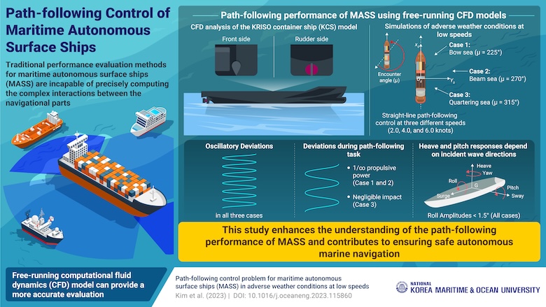
In light of these guidelines and the need for assessing path-following performance, a multinational team of researchers, led by Assistant Professor Daejeong Kim from the Division of Navigation Convergence Studies at the National Korea Maritime & Ocean University, has recently studied the path-following performance of MASS using a free-running computational fluid dynamics (CFD) model combined with the line-of-sight (LOS) guidance system, at low speeds under adverse weather conditions.
“We employed a CFD model based on a fully nonlinear unsteady Reynolds-Averaged Navier-Stokes solver that can incorporate viscous and turbulent effects and the free surface resolution critical to path-following problems, enabling a better prediction of path-following performance,” elaborates Dr. Kim. Their findings were made available online on September 25, 2023, and published in Volume 287, Part 2 of the journal Ocean Engineering on November 01, 2023.
The team employed the CFD-based analysis on the popular KRISO container ship model equipped with the autonomous LOS guidance system. The adverse weather conditions were modeled as disturbances from the bow, beam, and quartering sea waves, and these three cases were studied at three different speeds to identify the effect of forward speeds on the path-following performance.
Simulations revealed that the ship experienced oscillatory deviations in all the three cases. In the case of the bow and beam waves, these deviations decreased with an increase in propulsion power. Interestingly, in the case of quartering waves, there was a negligible effect of propulsion power on the deviations. Additionally, the heave and pitch responses of the ship were heavily influenced by the direction of the incident waves. Furthermore, in all three cases, the roll amplitudes were consistently below 1.5°. However, the team could not ascertain the effectiveness of increasing speed in improving path-following performance.
Elaborating on the implications of these findings, Dr. Kim said, “The proposed CFD-based model can provide a valuable contribution to enhancing the safety of autonomous marine navigation. Moreover, it can also offer low-cost alternatives to model-scale free-running experiments or full-scale sea trials.”
In summary, this study establishes a foundation for analyzing the path-following performance of MASS at low speeds in adverse weather conditions and could help in ensuring safer autonomous marine navigation.


 Mentor Graphics Corporation