• Skip to primary navigation
  • Skip to main content
  • Skip to primary sidebar
  • Skip to footer

3D CAD World

Over 50,000 3D CAD Tips & Tutorials. 3D CAD News by applications and CAD industry news.

  • 3D CAD Package Tips
    • Alibre
    • Autodesk
    • Catia
    • Creo
    • Inventor
    • Onshape
    • Pro/Engineer
    • Siemens PLM
    • SolidWorks
    • SpaceClaim
  • CAD Hardware
  • CAD Industry News
    • Company News
      • Autodesk News
      • Catia News & Events
      • PTC News
      • Siemens PLM & Events
      • SolidWorks News & Events
      • SpaceClaim News
    • Rapid Prototyping
    • Simulation Software
  • Prototype Parts
  • User Forums
    • MCAD Central
    • 3D CAD Forums
    • Engineering Exchange
  • CAD Resources
    • 3D CAD Models
  • Videos

Evan Yares

CAD in the pursuit of art: Shane McKenna

March 28, 2013 By Evan Yares 2 Comments

As an engineer, I often think about CAD as a tool for the engineering and design of technological products. But, every once in a while, I’m reminded that CAD can can be used in ways its makers never anticipated.

Shane McKenna is an engineer, designer, craftsman, and artist. I recently talked to Shane about how he uses CAD/CAM in his work, and he, as an aside, shared some of his art. Here’s what he said:

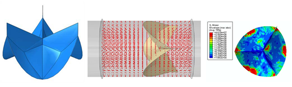
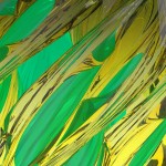
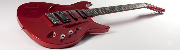
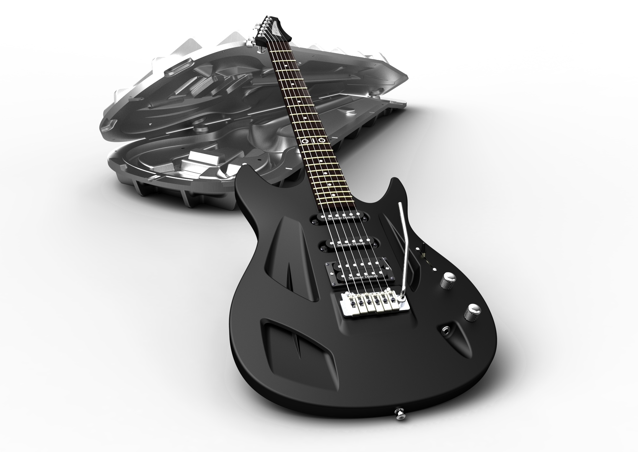
I always turn my tools to artistic endeavors sooner or later. It occurred to me that I could create abstract art by modeling shapes and then playing with the lighting, rendering and camera angles. I have not had a much time to play with these ideas lately, but would like to get them into a gallery at some point. I am open to doing commissioned pieces until I have created a large enough body of work to approach some galleries. These are all done in Solidworks.

Beneath the Waves
Black and Red
Planet
Summer Horizon
Textured Glass
With a Twist 1
With a Twist 2

If you like Shane’s work, you can contact him by email, at twoartistic@gmail.com.

Tomorrow, I’ll be following up, and posting an article about how Shane uses CAD, CAM, and 3D scanning in his (more conventional) work.


Filed Under: Evan Yares, Featured, News, SolidWorks Tagged With: SolidWorks

How would you design an electric motorcycle?

March 26, 2013 By Evan Yares 1 Comment

I often find myself looking at manufactured products, and wondering “how would you go about designing something like that?”

For some things, the sheer scale of the problem is so large that it’s hard to wrap your head around it.  But, there are many things that are more human scale, in complexity and difficulty. A good example is an electric motorcycle.

Some time back, I was having a conversation with some folks from  a company that does crowd-sourced engineering projects, about ideas for interesting projects. I suggested an electric motorcycle.  My thinking was that, with the availability of standard motors, control electronics, battery packs, and lots of OEM parts (forks, wheels, brakes, and even frames), it would be an interesting exercise, with relatively simple engineering, and an emphasis on industrial design.

I was reminded of this conversation when I learned I’d be hosting a webinar with industrial designer and engineer, Nout Van Heumen. Nout has become somewhat of a rock star in the Dutch industrial design scene. While his regular job is pretty much standard engineering work, his side job is a lot more fun: doing industrial design of some very cool projects. One project of particular note is the Orphiro electric motorcycle.

orphiro5

Nout will be talking about his approach to designing the Orphiro during our webinar this morning, at 8AM PST (11AM EST). You can register for it at http://www.designworldonline.com/webinar-how-to-deliver-real-time-concept-design-with-ptc-creo-2-0/

UPDATE: We just finished the webinar.  Here are a few of my takeaways:

Here are some  of my take-aways:

  • Think, from the beginning, in terms of what the manufacturer needs to make the part. In the examples Nout showed, his deliverable included both the parts and the molds to make them.
  • Don’t be afraid to start over, if the structure of your model isn’t working out right.
  • You don’t need to be a CAD genius to do impressive work, but you do need to master your tools.
  • Creo 2.0 seems at home modeling beautiful aesthetic parts.

We recorded the webinar, and after it is edited, it will be available for replay, at the link shown above.


Filed Under: Creo, Evan Yares, Featured Tagged With: Creo, Industrial Design, PTC

Rock and Roll industrial design

March 25, 2013 By Evan Yares Leave a Comment

I’m always interested in how people use CAD software to do interesting projects.

Nout Van Heumen is an industrial designer and engineer whose day job, so to speak, is in the packaging and insulation business. But Hout has developed a name for himself by taking on some really interesting freelance jobs.

One of his projects that I particularly like is the Aristedes OIO guitar. If you check out the picture of this guitar, you can see that it’s pretty cool looking. It’s also pretty innovative.

aristides-OIO-redmetallic-20133m

Tuesday morning, from 11:00 to 11:30 AM, Eastern time, I’ll be hosting a webinar with Nout, where he talks about his approach. Though PTC is sponsoring this webinar, it’s not going to a big sales pitch. It’s going to be a person talking about how he designs cool stuff.

My sense is that this webinar is going to be really interesting for anyone who is interested in conceptual design. Even people who don’t use Creo (which happens to be Nout’s tool of choice.)

So, please join Nout and myself tomorrow. You can register for the webinar here:

http://www.designworldonline.com/webinar-how-to-deliver-real-time-concept-design-with-ptc-creo-2-0/

o1o-mould


UPDATE:  Webinar is over.  Nout showed the new Aristedes 020 guitar, as well as the mold used to make it.  Interesting how he planned out the mold parting line, right from the beginning.

We will have a recording of the webinar available for replay, as soon as it is edited.

Filed Under: Creo, Evan Yares, Featured Tagged With: Creo, PTC

NVIDIA Kepler GPUs are finally here

March 8, 2013 By Evan Yares 4 Comments

nvidia-quadro-kepler
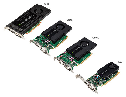
It’s taken awhile, but the new generation of NVIDIA GPU graphics cards are out.

Why does it matter? Well, short of performance issues—and these cards are fast indeed—the Kepler GPU represents a product inflection point for NVIDIA. It’s the “new model” – the presumptive choice among NVIDIA graphics cards for CAD workstations.

Up until now, NVIDIA has been shipping justs a few models of Kepler-based cards. The Lenovo W530 notebook that I’m using to write this post has a Quadro K2000M (the “K” means Kepler, the “M” means mobile), which is their fastest card for 15” class mobile workstations. The high-end K5000 has been out since October.

Here’s a table, listing the range of Kepler-based cards for desktop workstations:

QUADRO
KELPER DESKTOP WORKSTATION SPECIFICATIONS
BOARD FEATURES K5000 K4000 K2000 K2000D K600
Memory
Size
4GB
GDDR5
3GB
GDDR5
2GB
GDDR5
2GB
GDDR5
1GB
DDR3
Max
Power
122W 80W 51W 51W 41W
Power
Connector
1x
6-pin
1x
6-pin
Number
of slots
2 1 1 1 1
Simultaneous
Displays
4 4 4 4 2
Display
Connectors
DVI-I
(1)DVI-D (1)

DP 1.2 (2)

DVI-I
(1)DP 1.2 (2)
DVI-I
(1)DP 1.2 (2)
DVI-I
(1)DVI-D (1)

mDP 1.2 (1)

DVI-I
(1)DP 1.2 (1)
Single
Precision Performance (GFLOPS)
2168 1244 732 732 336
Price
(MSRP)
$2,249.00 $1,269.00 $599.00 $599.00 $199.00

You probably want to know which card you should choose, don’t you?

Let me tell you about the extensive comparative benchmark test I ran on the full line of NVIDIA cards. Or not. Instead, of doing that, I called my old friend David Cohn, and asked him what he thought. David regularly does full-on tests and reviews of graphics cards. For example, he reviewed the Quadro K5000 in the January issue of Desktop Engineering, and was duly impressed. Even though it’s the top of the Kepler line, it provides a lot of bang for the buck.

His observations confirmed my experience, which is that most CAD users should choose the mid-range card. In this case, the K2000 (or the K2000D, which comes with different display connectors.)

While the K600 is a perfectly competent card, it is noticeably less responsive in run-of-the-mill CAD use than the K2000. The difference in performance is more than worth the $400 difference in price.

And, while both the K4000 and K5000 are smoking hot cards, you only experience their power when running visualization type applications. The simple shaded models used in day-to-day CAD work just don’t require the capabilities of a high-end GPU.

Of course, all this is a big fat generalization. There are plenty of exceptions—cases where software developers have specifically tuned applications to use GPUs to their full potential.

Here’s how I’d put it: If I were to get a phone call from the brother-in-law of a friend, and he wanted to know what GPU card to buy for his CAD system, I’d tell him to get a  K2000. But, between you and me, when it comes to which card I’d get for my own workstation, the answer is different.  I choose the K5000.  I’ll tell you why in an upcoming post.

NVIDIA www.nvidia.com

Filed Under: CAD Hardware, Evan Yares, Featured Tagged With: NVIDIA

The new Autodesk

February 27, 2013 By Evan Yares 3 Comments

I received an excited email from Autodesk last week, offering to share some news under embargo.

What was the news? A new Autodesk logo.

autodesk_logo_screen_color_black_med


I wondered, why does this matter? What does it have to do with delivering value to customers. Here’s what Autodesk’s Chris Bradshaw has to say on the corporate blog:

“The new Autodesk is not just a surface change, but a reflection of how we are evolving our business.”

He does have a point there.  The Autodesk of a few years back was primarily a desktop applications company. With their moves in cloud and mobile, today’s Autodesk is quite a bit different. Add their new markets, such as personal fabrication and digital art, and you see a picture of a different company.

Personally, the changes I’d like to see are closer to home. The coolness of cloud and mobile don’t overshadow the fact that Autodesk is a tool supplier. Their products are used as tools by engineers and designers, to solve difficult problems.

Am I excited by the potential of Fusion 360? Absolutely. But hundreds of thousands of engineers and designers count on Autodesk Inventor. Just because Autodesk has new products, doesn’t let it off the hook to fix the problems in their old products. AutoCAD itself, at over 30 years old, still has weaknesses that should have been dealt with long ago.

I want to see more investment in bringing existing products up to the standard that users expect. That would be a new Autodesk I could get really excited about. New logo or not.


Filed Under: Autodesk News, Evan Yares, Featured Tagged With: Autodesk

Simulation for medical devices

February 15, 2013 By Evan Yares 1 Comment

This example of modeling and simulation of a medical device shows an aortic valve geometry (left), a model of the effect of blood flow on the valve in a blood vessel (middle), and an Abaqus finite element analysis (FEA) of the stress on the valve leaflets during the diastolic phase (right). This work was performed by Dassault Systèmes SIMULIA in conjunction with the FDA’s Center for Devices and Radiological Health (CDRH).

It’s no surprise that simulation is becoming more mainstream. Advances in technology, plus better integration with CAD software make that a foregone conclusion.

The United States Food and Drug Administration (FDA) has been seeing an increased number of submissions accompanied by simulation data. That sounds good on its face, but what if the simulation data is faulty, or unreliable?

The FDA is tacking that problem now, by reaching out to both the medical and software industries to establish guidelines for simulation, and by building a publicly available “Virtual Physological Patient.”

Cheryl Liu, a life sciences specialist with Dassault Systemes SIMULIA group, worked with the FDA to develop the following  article about the FDA’s efforts. I don’t often merely reprint articles here, but I think this one has a special value, in helping to put context to the importance of simulation for medical devices.  My thanks to Dassault Systemes for sharing it with me, so I could share it with you.

Simulation Now Recognized by FDA
as Essential to Medical Device Evaluation

by Cheryl Liu, Life Sciences Senior Product Experience Technical Specialist,
Dassault Systèmes SIMULIA

One of the toughest design engineering challenges is making a medical device that works flawlessly with the human body. The unique anatomy and physiology of every patient create physical complexities, and ever-shifting functional parameters, that must be thoroughly accounted for when producing a therapeutic product that may need to last a lifetime.

Domestic inpatient procedures involving medical devices—stents, heart valves, dental implants, spine and joint implants, surgical tools, blood pump, endovascular grafts, drug-eluting devices and more—totaled 46 million in the U.S. alone in 2006, according to the Centers for Disease Control (CDC). It’s a global market that is growing along with aging populations everywhere.

Computer simulation, already widely accepted in many industries, is increasingly being viewed as an important tool by medical device companies and their designers. It helps them visualize what they cannot see, explore the design space more fully, refine their ideas faster and more accurately—and reduce expensive prototyping and testing.

Solid mechanics simulations can help determine proper implant size, evaluate manufacturing tolerances, compare design geometries or consider next-gen devices. Fluid dynamics can be employed to identify high-shear stresses on blood vessels, regions of low flow, and potential for blood damage. And simulation-based product development processes can be linked in automated workflows, optimizing huge quantities of design data to provide exquisitely fine-tuned results that are of particular value for creating patient-specific medical devices.

FDA sees increasing numbers of applications that include simulation

As Life Sciences engineers embrace simulation, they are achieving increasingly accurate levels of precision when evaluating device function, including the ability to evaluate aspects of device performance not possible with bench tests alone. As a result, the Food and Drug Administration’s (FDA) Center for Device and Radiological Health (CDRH) is seeing a growing number of submissions for medical devices that include a simulation-data component.

The CDRH is responsible for regulating firms that manufacture, repackage, re-label, and/or import medical devices sold in the U.S. The submissions for these therapeutic devices typically contain data from four types of evaluation models—animal, bench, computational and human—to demonstrate a reasonable assurance of safety and effectiveness. When a company submits simulation metrics that supplement bench testing, this can help promote approval by demonstrating both the integrity of the proposed device and the required realistic device failure analysis. As the ultimate safety-and-effectiveness regulatory body between medical device manufacturers and patients, the FDA recognizes the value of such advancing technologies—and its own need to stay abreast of them—and has now begun actively encouraging the use of simulation in device evaluation.

However, the FDA has also put the industry on notice that verification and validation must go hand-in-hand with the use of simulation in applications. The CDRH is looking to quantify when a computational model is credible enough, and what its intended purpose is appropriate for a regulatory submission. Unclear reporting standards, insufficient data about geometries and boundary conditions, lack of validation metrics, incomplete understanding of physiological loads in the body, and variations in patient populations—any and all of these uncertainties can impact the relevance of simulation outputs.

SIMULIA contributes to advancement of knowledge

Noticing that a significant proportion of the applications they have seen in recent years have included simulations with Abaqus finite element analysis (FEA) from Dassault Systèmes SIMULIA, the CDRH reached out to us in 2010 for support in developing their own internal framework, and in-house expertise, for validating and regulating industry-submitted simulations.

SIMULIA presented at the FDA’s 3rd workshop on Computational Modeling of Medical Devices the same year. We continue to deliver on-site training courses to FDA reviewers about best practices in modeling and simulation and to partner with the FDA on aortic valve model development (Image 1). The FDA has also presented at our SIMULIA Community Conference and Regional User Meetings. Realizing the importance of model verification and validation (V&V), in early 2011, ASME and FDA launched the V&V 40 subcommittee to develop V&V guidelines for the medical device industry specifically; we are actively participating, along with others in the industry and software communities.

As one outcome of these efforts, the FDA will publish a guidance document titled “Reporting Computational Modeling Studies in Medical Device Regulatory Submissions” in 2013. Appendices will cover fluid and mass transport, solid mechanics, electromagnetism, control loops, thermal transport, and ultrasound. Publication date updates can be found on the CDRH website at http://www.fda.gov/MedicalDevices/DeviceRegulationandGuidance/GuidanceDocuments/default.htm

The ‘Virtual Patient’ idea is born

As knowledge about the importance of simulation grows, another priority for the FDA is the creation of a publicly available ‘Virtual Physiological Patient’ of human body computer models in different disease states (Image 2). This is not intended to be a single model encompassing every function and disease at once. Rather, the project will comprise a library of verified and validated submodels and data based on the combined expertise of those groups in the relevant disciplines, i.e., cardiology, orthopedics, software and so forth.

Broad cross-industry collaboration between medical device manufacturers, academia and software companies is being harnessed for the FDA’s Virtual Physiological Patient project.

The goal of the Virtual Physiological Patient project is a shared point of reference that will improve understanding of model attributes and limitations, and provide discrete models, data and simulations validated for regulatory evaluation. Peer review by experts in academic, government, and industry will ensure robust V&V and provide periodic assessment. SIMULIA is contributing expertise to a group that is developing a computational model for the evaluation of a diseased femoral artery for stent evaluation.

Newly Launched Public-Private Partnership will benefit all parties

Concurrent with the development of the Virtual Physiological Patient concept, the FDA is reaching outward to device manufacturers, software providers, and medical professionals to form a Regulatory Science Public-Private Partnership. Launched in December of 2012, the partnership is called the Medical Device Innovation Consortium (MDIC). Specific details are available at http://www.deviceconsortium.org/ .

The idea is to create an opportunity for information gathering in a pre-competitive state, i.e., not device-specific, but disease-specific.  For example, if the heart valve community were interested in a comprehensive evaluation of the structure and function of heart valves, costs could be minimized through non-profit group funding and participation in the development of tools and resources for modeling and simulating of a range of valves. All results would be shared. End-stage renal disease is another area recently identified by the FDA as a priority. Industry forums on this topic are already underway.

The medical device industry can only benefit from such endeavors. Individual device design copyrights certainly need to be protected, but the tradition of publishing evidence-based research results in order to move the entire body of medical knowledge forward has resonated in the Life Sciences throughout the history of medicine. A deep understanding of the function of the living body is critical to every medical-device developer, and sharing the data that lie at the core of that understanding can be accomplished without infringing on any one company’s patents.

The FDA views modeling and simulation as incentives to innovation that can reduce the time and cost of device design, assessment, and manufacturing. It is in all our interests—the medical device industry, the regulatory agency, and software companies—to collaborate to ensure that the power of simulation is increasingly utilized to solve the wide range of challenges in medical device development. We can all agree that the ultimate goal is the safety and effectiveness of medical devices for every physician who uses them, and every patient who needs them.

Special thanks to Dr. Tina Morrison, Dr. Nandini Duraiswamy and Dr. Donna Lochner of the FDA for their assistance in preparing this article.

For More Information: www.fda.gov

Read more about how the FDA is promoting innovation in “High Stakes Balancing Act” in COMPASS magazine www.compassmag.3ds.com.


Filed Under: CAD Industry News, CAE, Evan Yares, Simulation Software Tagged With: Dassault Systemes, FDA, Simulia

Cyber-Physical Systems: A call to action

February 13, 2013 By Evan Yares 1 Comment

Cyber-Physical SystemsNIST, the National Institute of Standards and Technology, has just published a trio of reports on Cyber-Physical Systems (CPS).

“CPS go well beyond today’s ’embedded systems,’ which are largely task-specific machines that operate under computer control. Anticipated CPS uses such as intelligent vehicles and highways and next-generation air transportation will be significantly more ambitious, diverse and integrated than those of today’s task-specialized embedded systems.”

The NIST reports include a call to action that points to the importance of CPS:

The future applications of CPS are more transformative than the IT revolution of the past three decades. Unparalleled analytical capabilities, real-time networked information, and pervasive sensing, actuating, and computation are creating powerful opportunities for systems integration. Next generation CPS will be able to execute extraordinary tasks that are barely imagined today. These new capabilities will require high-confi dence computing systems that can interact appropriately with humans and the physical world in dynamic environments and under unforeseen conditions. Achieving these capabilities presents a complex and multi-disciplinary engineering challenge.

Future CPS have many sophisticated, interconnected parts that must instantaneously exchange, parse, and act on detailed data in a highly coordinated manner. Continued advances in science and engineering will be necessary to enable advances in design and development of these complex systems. Multiscale, multi-layer, multi-domain, and multi-system integrated infrastructures will require new foundations in system science and engineering. Scientists with an understanding of otherwise physical systems will need to work in tandem with computer and information scientists to achieve eff ective, workable designs. Standards and protocols will be necessary to help ensure that all interfaces between components are both composable and interoperable, while behaving in a predictable, reliable way.

As a CAD user, you are going to be expected to create models that go beyond the normal fit and function requirements of today. They’ll need to actually represent the performance and behavior of the parts and assemblies they represent, as they are integrated into larger systems.

Here is a table, taken from the reports, that shows some of the applications of cyber-physical systems:

Cyber-Physical Systems

Take some time, and visit the NIST page on Cyber-Physical Systems, and read the reports.  If you have a chance, leave me a comment here, and let me know what you think.

Filed Under: CAE, Evan Yares, Featured, News, Simulation Software Tagged With: NIST

CATIA’s latest design win: The Iranian F-313 stealth fighter

February 5, 2013 By Evan Yares 31 Comments

A few days ago, Iran announced a new indigenous stealth fighter: the Qahar 313.

Theaviationist.com has covered the plane in quite a bit of depth. The prototype of the F-313 was presented to Iranian President Mahmoud Ahmadinejad, then displayed publicly. The FARS News Agency provided a large number of photos of the jet, showing many of its features.

Iranian television showed videos of the plane, both on display and flying. Starting at 1:48, some computer screens showing the software used to design the F-313 appear in this video.

Do you recognize the programs? The Iranian MEHR News Agency confirmed that the F-313 was designed with CATIA CAD software, and Fluent CFD software.

There are some talented CATIA engineers in Iran. You can check out some of their work at GrabCAD. Still, I’m pretty certain that neither Dassault Systemes nor ANSYS  supplied their software products to the Iranian Ministry of Defense—nor to anyone else in Iran—with the intention that it be used to develop military systems. (The U.S. and France are members of a variety of multilateral nonproliferation regimes which likely constrain the export of such software.)

Funny thing though: by all appearances, neither CATIA or Fluent were actually used by Iran to design a new stealth fighter. Rather, they were used to design a non-functional mock-up, and a radio-controlled scale model.

Look carefully at the pictures of the F-313. Even if you’re not an aeronautical engineer, you can see some problems. Size and proportions are wrong. Landing gear are wrong. Cockpit is wrong. Canopy is wrong. There are no service access plates. No nozzle on the jet engine. Too small air intakes, positioned wrong. And the entire plane appears to be made out of plastic (or fiberglass.)  In forums around the web, people have been pointing out undeniable signs that the plane shown in the pictures is a mock-up that, as designed, could never fly.

What of the videos showing the F-313 flying? Look carefully. Does it look like a real plane, or a scale model?

The thing that I get the biggest kick out of is this still, from the above video:

Q-F313

Notice that the model is made up mostly of flat non-aerospace surfaces? And notice that the feature tree is all in English?  Seems curious to me: Why would Iran design a plane in English and even cover it with English language signage? I don’t have a good answer, other than to guess that the entire project was an exercise to impress people who speak English.

While I am having a little bit of fun with Iran, I’m of the opinion that, if they wanted to actually design and build a jet fighter, CATIA and Fluent would be good tools to use. As a start. But they’d not be enough. Along with other software tools (and a lot of people and process), they’d need some manufacturing equipment that they don’t have, and can’t easily get. To learn more, read The Machines that made the Jet Age, by Tim Heffernan.


Filed Under: Evan Yares, Featured, News Tagged With: ANSYS, Dassault Systemes

SolidWorks 2014: No obvious surprises

January 28, 2013 By Evan Yares 5 Comments

Bernard Charles, explaining where SolidWorks fits in.

There was a time, years back, when SolidWorks users complained because the annual updates of the software included so many major new capabilities that it was hard to keep up.

SolidWorks is a mature product now, and the pace of adding major new capabilities has slowed down quite a bit.

Now the big emphases with new SolidWorks releases are performance, stability, and quality. New capabilities are slanted towards making making existing users happy, and seem, at least to me, to have the common characteristic that they can be added without creating stability problems or regressions. SolidWorks 2013, for example, had a fairly good number of enhancements, but few, if any, of them appeared to be the type of things that that would have required making deep changes to the core of the software.

SolidWorks 2014, due to ship later this year, is likely to continue the trend, with a variety of relatively small enhancements, designed to please existing users. The new version was previewed at SolidWorks World last week. Rather than listing the new features here, I recommend checking out Ricky Jordan’s Blog, where he did a nice job of covering them.

Still, there is one new feature that I find quite interesting: the style spline. SolidWorks splines are not particularly well suited to creating class-A surfaces. Whether it was intentional, or a mistake made long ago, it’s been a problem for users who need high quality surface continuity. I’ve wondered how this could be fixed—my guess was that if the SolidWorks programmers changed the behavior of splines to fix their continuity, they’d introduce incompatibilities with older parts files. It looks like their answer was a good one: introduce a new class of spline specifically designed to give better control and smoothness.

It’s probably risky to predict anything about SolidWorks 2014, since it’s not due to ship for quite a while. But my completely subjective impression is that this may be another good release.

Speaking of future releases: I continue to dig to find information on future plans for SolidWorks. You may know that there’s been uncertainty and concerns among some users about whether Dassault Systemes might eventually “retire” the current SolidWorks generation. Here’s my reading: It’s not going to happen for a very long time.

I figure DS is about as likely to retire SolidWorks as Autodesk is to retire AutoCAD. Neither company is run by people who are dumb enough to kill off products that make them hundreds of millions of dollars a year.


Update: Vajrang Parvate, Director of SolidWorks Product Development, recently made this comment on the SolidWorks forum:

“We invested several man-years in changing some of the core components of the SolidWorks source code in SW2013 – the compiler, the VBA engine that drives macros and equations, the .NET version we run on, support for Windows 8… to name just a few. This was done across the product line – Core SolidWorks, Simulation, eDrawings, Routing, CircuitWorks, etc. and we are continuing to do those kind of long-term investments in the SolidWorks source code. SW2014 development is going on right now and our Product Definition and Product Management teams have begun initial planning for SW2015.

“I hope this says something about the longevity and the future of the products from SolidWorks you know and use today. Bottom line: They are not going away.”

It’s a nice reassurance that SolidWorks is going to be around for a long time. But, it begs a question: Doesn’t this kind of investment qualify as “making deep changes to the core of the software?”

No.  This work was certainly tedious and time consuming, but not “difficult,” in the sense that making major functional changes to SolidWorks would have been. It it was likely necessary to insure compatibility with the new versions of Microsoft’s development tools.

It’s hard to give SolidWorks major brownie points for doing something that every software developer who wants to support Windows 8 has to do.

Had Vajrang said that they’d invested the time and effort to add support for DirectX (as an alternative to OpenGL), I would have been impressed.


Filed Under: Evan Yares, Featured, SolidWorks, SolidWorks News & Events Tagged With: Dassault, SolidWorks

The roots of CAD, part 2: The design process

January 28, 2013 By Evan Yares 2 Comments

Steven Coons
Steven Coons, in front of the MIT Lincoln Laboratory TX-2 computer

In 1959, Douglas Ross, Steven Coons, and John Ward, along with their colleagues, started the MIT Computer-Aided Design Project, and planted the seeds that grew to define modern CAD.

At the 1963 Spring Joint Computer Conference, Steven Coons delivered a seminal paper on CAD: An Outline for the Requirements for a Computer-Aided Design System. A few days ago, in part one of this article, I published an except from that paper, where Coons described the original thinking at MIT about CAD. Today, I’m going to except an even more interesting section on the design process.

The distinctions that Coons makes in this paper are still relevant and valuable 50 years later, and point to way to today’s model-based engineering and design methodologies.


The Design Process

The design process begins with a graphical description of a proposed device or system to satisfy a human need. To say that the description is graphical is to assert that at the very inception of an idea the designer’s understanding of his creation is almost visceral instead of intellectual. He perceives his idea at first not in the perfection of a well-turned English word description, nor in the precision of a mathematical formula, but in some nebulous assembly of building blocks of structure, vaguely beheld; he “feels” his creation. The sketch forms the natural bridge between these vague stirrings of the imagination and the subsequent precise statement of the refined details of the concept.

At this early stage, decisions to keep, to modify, or to discard part or all of the original concept are made in a qualitative way, based upon qualitative criteria. The modified concept leads to further qualitative decision making, and to further modification of the concept. While this is going on, the concept which was at first nebulous and incomplete begins to assume a more concrete solid character; it becomes better defined, until at some stage it is well enough defined to permit more precise analytical tools to be applied.

In the design process, the designer is concerned with a large set of variables, some continuous (like the weight of a part) some belonging to discrete “point sets” (like the material: steel, brass, lead, plastic.) Moreover, these variables are interrelated, or cross coupled, in a very complex way. Some of the cross couplings are weak, some are strong. If the relationships happen to be linear, the cross couplings are constant in strength, but usually the relationships are non-linear, and the mutual influences of the various variables change with their values.

The designer structures such relationships so that he can thread through them, taking advantage of the loose couplings where possible, to obtain hopefully an exact, but more usually a first, or second, or closer approximation to the values of the variables. It is not at all unusual for this structuring to be done graphically, in the form of block diagrams or linear graphs or information flow charts. Thus he uses a graphical form for both the topological and geometric description of the design, and also for its abstract description in terms of physical function.

At the conclusion of the design process, the final result must be carefully defined so that it can be built. This is the function of layout draftsmen and detail draftsmen. If automatically controlled machines are involved in the fabrication processes, programmers are also a part of the system.

When we look at such a design sequence we see a few engineers performing highly creative tasks at the beginning, coupled with a very large number of draftsmen and technicians who perform relatively uncreative tasks over a fairly long period of time. Some of these tasks require high degrees of intellectual effort, such as stress analysis or aerodynamic analysis, but they are none-the-less not in themselves of a creative nature (except in those cases where new mathematical techniques are designed and put to use). Other tasks are obviously of a purely mechanical nature; for example, a detail draftsman does nothing creative whatever. At the worst, he merely traces the outline of a part from the layout drawing, and adds the dimensions. Usually this drawing goes directly to some machinist or patternmaker in the shop, but sometimes it is used by a part programmer and converted by him into symbolic information for use by a computer to prepare punched tape for automatic fabricating machinery. These are all essentially mechanical operations, however, and it is quite clear that at least in principle, the computer can be made to deal with them all.


Excerpted from: Coons, Steven, “An Outline for the Requirements for a Computer-Aided Design System,” Proceedings of the Spring Joint Computer Conference, Detroit, Michigan, May 21-23, 1963.

Filed Under: Evan Yares, Featured, News Tagged With: cad

  • « Go to Previous Page
  • Go to page 1
  • Go to page 2
  • Go to page 3
  • Go to page 4
  • Go to page 5
  • Interim pages omitted …
  • Go to page 10
  • Go to Next Page »

Primary Sidebar

3D CAD NEWSLETTERS

MakePartsFast

Follow us on Twitter

Tweets by 3DCADWorld

Footer

3D CAD World logo

DESIGN WORLD NETWORK

Design World Online
The Robot Report
Coupling Tips
Motion Control Tips
Linear Motion Tips
Bearing Tips

3D CAD WORLD

  • Subscribe to our newsletter
  • Advertise with us
  • Contact us
Follow us on Twitter Add us on Facebook Add us on LinkedIn Add us on Instagram Add us on YouTube

3D CAD World - Copyright © 2022 · WTWH Media LLC and its licensors. All rights reserved.
The material on this site may not be reproduced, distributed, transmitted, cached or otherwise used, except with the prior written permission of WTWH Media.

Privacy Policy