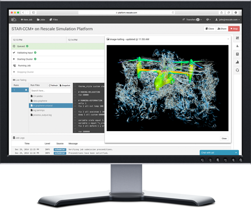
Additive manufacturing, the Internet of Things, and other technologies are smashing through the wall that used to separate design and manufacturing. A number of programs being launched this year promise to merge design and manufacturing into one function.
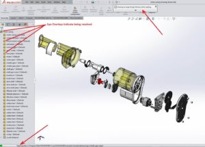
One of those programs is SOLIDWORKS 2018, which includes new tools and enhancements to help engineers get their designs to manufacturing faster. The user interface, for example, lets engineers use a pen or their finger on the touch screen rather than a mouse to design objects. This more natural approach can speed up design.
SOLIDWORKS CAM for CNC machining
CAMWorks, now part of SOLIDWORKS CAM, lets users seamlessly integrate design and manufacturing. It has rules-based machining and automatic feature recognition to streamline and even automate CNC manufacturing operations.
Tolerance Based Machining
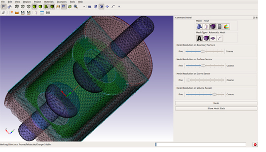
Mesh data
Engineers can work with mesh data similar to how they work with surface or solid geometry. Combine, intersect, split, move/copy, cut with surface, and check for interference. In addition, quickly fit surface bodies to regions of mesh models.
More flexibility with 3D Interconnect
Users can seamlessly work with such file formats as ACIS, STEP and IGES, and automatically update designs whenever new files are received. In addition, 3D Interconnect now supports internal file information like custom properties, materials properties and reference axes.
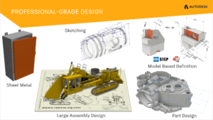
Refined sheet metal design tools
SOLIDWORKS 2018 includes tab and slot features for self-fixturing of parts for welding, a normal cut feature to ensure clearances are included for manufacturing, and tools to easily create or flatten corners that include three bends.
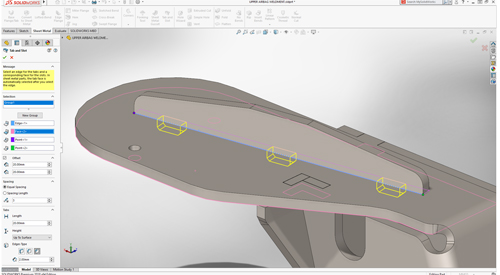
Tab and Slot-sheet metal
Efficient collaboration
Speed up design detailing while also streamlining and automating downstream manufacturing tasks, such as CNC programming and inspection, by importing 3D models along with PMI from all major CAD formats, as well as STEP 242.
Electrical routing
Routing is fast with greater detail. Users can drag and drop in-line connectors and support shrink-wraps and boots. Users can also flatten a route in drawing with support for clips and disjointed routes.
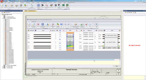
Elec-MultiLevel Terminal
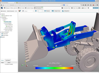
Generative design for better part geometry
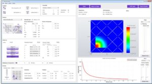
The SOLIDWORKS Simulation Topology Study tool can help users automatically optimize the shape of a design based on weight, function, and manufacturing criteria. This features takes into account simulation data and manufacturing constraints.
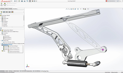
Topology Study MFG Controls
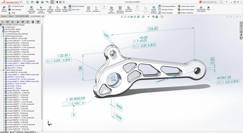
SOLIDWORKS inspection support for MBD
Users can create inspection documentation directly from 3D models with Production Manufacturing Information, as well as from 2D drawings, PDFs, and TIFFs. SOLIDWORKS Inspection is now integrated with SOLIDWORKS PDM, and supports SOLIDWORKS part and assembly files (*.sldprt, *.sldasm), as well as non-native 3D CAD formats.
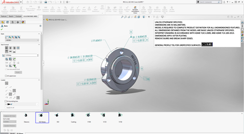
MBD default all-over profile tolerance
Project and process management
SOLIDWORKS Manage provides data management, project management, and process management all in one package. It adds powerful project, process, and item management capabilities to SOLIDWORKS PDM Professional.
Design branching and merging
Users can investigate different design approaches without affecting approved files with the new features in SOLIDWORKS PDM. The software also helps to streamline the process of working with external users.
Automated PDF creation for SOLIDWORKS drawings
SOLIDWORKS PDM Standard can automatically create PDFs from SOLIDWORKS drawings through workflow transitions. This feature eliminates the manual creation of PDFs.
Automatic revision table update
SOLIDWORKS PDM manages and automatically updates SOLIDWORKS revision tables.
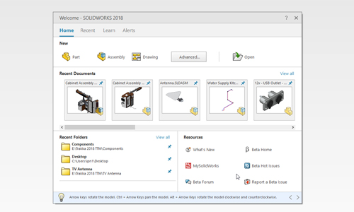
Cloud-connected SOLIDWORKS
Empower desktop computers with cloud convenience through online licensing. SOLIDWORKS Online Licensing makes using your license on multiple machines effortless. The SOLIDWORKS login moves custom content and settings to any machine on which SOLIDWORKS is installed. The SOLIDWORKS Admin Portal allows easier management of SOLIDWORKS products and services.
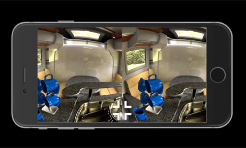
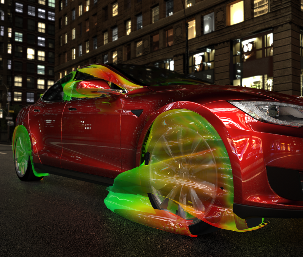
Visualize VR
Dassault Systemes
www.3ds.com