• Skip to primary navigation
  • Skip to main content
  • Skip to primary sidebar
  • Skip to footer

3D CAD World

Over 50,000 3D CAD Tips & Tutorials. 3D CAD News by applications and CAD industry news.

  • 3D CAD Package Tips
    • Alibre
    • Autodesk
    • Catia
    • Creo
    • Inventor
    • Onshape
    • Pro/Engineer
    • Siemens PLM
    • SolidWorks
    • SpaceClaim
  • CAD Hardware
  • CAD Industry News
    • Company News
      • Autodesk News
      • Catia News & Events
      • PTC News
      • Siemens PLM & Events
      • SolidWorks News & Events
      • SpaceClaim News
    • Rapid Prototyping
    • Simulation Software
  • Prototype Parts
  • User Forums
    • MCAD Central
    • 3D CAD Forums
    • Engineering Exchange
  • CAD Resources
    • 3D CAD Models
  • Videos

Simulation Software

Using FEA to Study a Fixture Assembly

January 22, 2009 By admin Leave a Comment

Ionut Ghionea, Lecturer, Faculty of Engineering, University Politehnica of Bucharest


The finite element method (FEM) has become  a widely used and  indispensable engineering tool  for critically analyzing new component and product designs.  Since its introduction, continuous updates by most suppliers have made the FEM technique even more accurate and easier to apply. To appreciate just how much FEM has improved recently, its capabilities are illustrated in an example of a fixture design for attaching a wedge to two principal bolts on planar surfaces.   The fixture contains a circular eccentric gear (cam) and a two-arm bridle which clearly shows that the  cam’s working profile is a circular arc.


The scope of the finite-element analysis for this device is to identify the zones with high stresses and their values. This does not consider the stresses that result from the technological processes when the piece is machined, or the rigidity of supports and tightening elements.
The assembly consists of a bedplate, abutment bolts, a holder with a spherical head, a cam, an attachment flange for gripping cams, and associated hardware, Fig.1.


3fig1.gif


Fig. 1. The fixture device in isometric view.


The holder actuates the cam and fixes the piece on the device while friction forces hold the  eccentric gear in place.  To simplify the FEM calculus and explanations, the coiled spring is not represented. Bending, tension or compression stresses are applied to the components as the device is actuated.


Setting constraints
This analysis uses the Generative Structural Analysis module from the CATIA software package. Also, the 3D modeling of the device and its assembly require two other modules: Part Design and Assembly Design. A very important step in the FEM analysis process addresses how the device’s components are assembled using numerous constraints of the following types: coincidence, surface contact, linear contact, offset and fix, Fig. 2.


3fig2.gif


Fig. 2. Fragment of the assembly constraints list.


In this example, these constraints apply:
Coincidence constraints between the axes of the swell pin and of the cam hole.


Coincidence constraints between the axes of the dowel screw and its corresponding nuts.


Linear-contact constraints between the active surface of the cam and the guide’s planar surface, and between the tightening curved surface from the bridle’s end and the piece’s planar surface.


Surface-contact constraint between the supporting surface of abutment bolts and the bedplate.


Each component is made of steel, with appropriate material properties applied: Young modulus (2 X 10¹¹ N/m2), Poisson ratio (0.266), density (7860 kg/m3), thermal expansion (1.17 X 10⁻⁵ K) and yield strength (2.5 X 10⁸ N/m2).


Using the module Generative Structural Analysis, a node network discretization is done for each component, establishing the dimension, the type of each finite element and the tolerance
between the real model and the discretized one, Fig. 3. The finite element type is chosen as Linear because a Parabolic element type could extend calculation time excessively.  (Later, the effect of this choice will be examined.)


3fig3.gif


Fig. 3. Node network discretization.


Using the assembly constraints, the next step involves setting the physical constraints, necessary in the simulation of the tensile stresses, generated by the application of a force on the holder. Thus, the physical constraints are chosen after the assembly constraints and they are of these following types: Fastened Connection Property, Pressure Fitting Connection Property and Contact Connection Property.  A small section of these physical constraints is shown, Fig 4, along with some of their symbols positioned on the respective components.


As an example, the coincidence assembly constraints between the swell pin axis and the axis of the cam hole become physical constraints of type Fastened Connection Property. The coincidence assembly constraints between the abutment bolt axes and the corresponding axes drilled in the bedplate become physical constraints of type Pressure Fitting Connection Property. Also, the surface contact assembly constraint between the guide and the bedplate become a physical constraint of type Contact Connection Property.


3fig4.gif


Fig. 4. Fragment of the physical constraints list and symbols.


The next step in this application consists of adding a fixing restraint (Clamp), positioned on the base surface of the bedplate. In this step we establish the applied load on the holder, a Distributed Force of 600 N value. This force has the device’s working direction (holder-cam-bridle), tightening the piece. The specification tree, positioned on the left side of the CATIA interface, will show the sub-elements “Clamp.1” and “Distributed Force.1”, Fig. 5.


3fig5.gif


Fig. 5. Application of the fixing restraint and the loading force.


Begin analysis
Launching of the finite-element analysis process can begin after these preliminary stages (choosing the discretization values and imposing constraints and loads)  The procedure is very specific to the CATIA software. Finally, the specification tree is completed with the sub-element Static Case Solution, which may contain different solutions depending on the instruments used: Deformation, Von Mises Stress, Displacement, Principal Stress and Precision.


To determine the tensions caused by the applied loading force, use the Von Mises Stress results. Use of the Image Extrema instrument allows highlighting (locating) the minimum and maximum tension values, at a global or local level. The specification tree, Fig. 6, presents the sub-elements “Von Mises Stress” and “Extrema” which shows on the device’s 3D assembly model some indicators of the extreme values. This figure also shows the node network discretization.


3fig6.gif


Fig. 6. Representation of the Von Mises results and the localization of the extreme tensions.


From the colors and values palette, which correspond to the Von Mises model representation, you can see the maximum tension in the assembly is 2.63 X 10⁷ N/m2, located on the holder, in the joint area between its end and the cam. The first analysis shows an error of 45.81%, but this result is too inaccurate, so an assembly-node network-discretization refinement is necessary, followed by another analysis process, applying the instrument New Adaptivity Entity.


3fig7.gif


Fig. 7. Tension representation and values for cam.


In this analysis, the user imposed a 20% error after three iterations, but in the second step of analysis, the error is decreased only to 26.57%. That eror reduction is accompanied by a maximum tension increase on the holder, in the same area of joint: 5.18 X 10⁷ N/m2.  If these values (error percent and tension) are not acecptable, another node-network discretization refinement will be required, using the finite element type Parabolic, which will further decrease the percentage of error.


Results of analysis
The CATIA facility shows tension for each component (Figs.  7, 8 and 9) indicating tensions in colors-and-values palettes for these three components.


3fig8.gif


Fig. 8. Tension representation and values for bridle.


3fig9.gif


Fig. 9. Tension representation and values for dowel screw.


• For the cam, the most stressed areas are: the assembly hole with the holder (3.11 X 10⁷ N/m2), the assembly hole with the swell pin (1.1 _ 107 N/m2) and the contact surface with the guide.


• For the bridle, the most stressed areas are: the surfaces of the assembly hole with the swell pin (2.25 _ 107 N/m2) and the planar contact surface with the conical pocket washer (3.35 _ 106 N/m2). On the contact area with the piece, the bridle presents tensions of 1.1 _ 105 N/m2.


• For the dowel screw, the most stressed areas are at the upper end, in the proximity of the assembling zone with the nuts (6.66 _ 106 N/m2).


• The assembly zone with the bedplate is stressed to a tension of 6.17 _ 106 N/m2. Thus, the tension distribution along the dowel screw indicates that it is loaded and bent.


: Design World :

Filed Under: Simulation Software

FEA Electromagnetic Simulation of Motors and Generators

January 22, 2009 By admin Leave a Comment

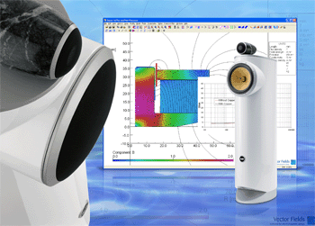
Vector Fields offers new capabilities for its design software for rotating electrical machinery. The software combines finite-element analysis (FEA) modeling with a design entry system that lets you create models of electric motors or generators in minutes.

The software is an application-specific version of the Opera package, providing a front-end to the electromagnetic simulator that speeds design entry by means of ‘fill in the blanks’ dialog boxes. You select the form of motor or generator you want to design from a list of common types including induction, brushless permanent magnet, switched reluctance motors, and synchronous motors or generators.  Then, you enter a list of parameters to define mechanical geometry, material properties and electrical data, and the model is automatically created. Parameters can include diameters of rotor, stator; and shaft, stator tooth width, and the number of stator slots.

New modeling features with this release include an extended range of cage geometries for induction motors. You can choose from six starting points including circular, bullet and square, plus variations and combinations of these shape elements. You can also define notch shapes on stator teeth as well as wedge geometries.  The choice of geometries for wound rotor synchronous motors has been expanded in a similar way.  These options give you the means to quickly arrive at a model, even for proprietary design techniques.

If you need to incorporate unusual features in a design, you have open access to scripting codes that generate models, and can modify them at will to create a proprietary automated design process. A library of material properties is also included and is selected by means of a drop-down menu. 

Using the scripts provided, you can generate motor or generator models in minutes. You can then simulate electromagnetic performance and view results such as the torque produced as a function of position, or the static analysis of flux linkage in the phases of the machine as a function of position and excitation. You can try design ideas easily by varying the values of model parameters.

An automatic optimization tool is optionally available.  It automatically selects and manages multiple goal-seeking algorithms to find the best design to a problem, even if you specify several or competing objectives.

Facilities include modeling the external circuit feed to the machine, as well as the mechanical load. ‘Multi-physics’ capabilities available in the package show you the effects of temperature rise, or the mechanical stresses that torque produced by the electric field will have on the machine’s component parts.

Vector Fields Inc.
www.vectorfields.com

:: Design World ::

Filed Under: Simulation Software

Handling more data

January 22, 2009 By admin Leave a Comment

FIELDVIEW 11.1, from Intelligent Light, delivers scalable post-processing to users of multi-core workstations, large shared memory systems, and cluster computing environments. As the size of data needing analysis has grown by 25 times, programs have increased the speeds of their processors. Fieldview offers a five times speed increase on 8 CPUs, necessary when post-processing realistic, multigrid CFD simulations on systems using AMD Opteron processors.

www.ilight.com

::DW::

Filed Under: Simulation Software

Students explore airflow in early aircraft flight

January 22, 2009 By admin Leave a Comment

One hundred years ago, Alberto Santos-Dumont flew one of the first heavier-than-air
machines in Europe. Recently, a team of Brazilian students used the ANSYS ICEM CFD
and CFX software to analyze and understand airflow around that plane’s surface.

new-mesh2.gif

For the CAD model of the 14-Bis students meshed surfaces using hexahedral elements
and represented volumes with a tetra/prism mesh. ANSYS ICEM CFD software created
both high-quality surface and volumetric meshes.

Santos-Dumont was an aircraft pioneer. On October 23, 1906, he flew his aircraft, named
the 14-Bis, almost 200 feet at Bagatelli Field in Paris, France, witnessed by officials from
what would become the Federation Aeronautique Internationale. The 14-Bis consisted of
a long neck at the front of the craft with wings in the rear. The pilot maneuvered the
plane from a standing position.

The students used modern engineering simulation to demonstrate the 14-Bis’ ability to
fly. By analyzing drag and lift as well as engine thrust, the team simulated the flight
speed of the aircraft, nearly matching the recorded values.

picture2.gif

Qualitative analysis of the pressure field was provided through the ANSYS CFX
computational fluid dynamics software.

The plane model was developed using historic pictures, plans and discussion. Due to
complex geometry, the team used ICEM CFD software to create both high-quality
surface and volumetric meshes. CFX computational fluid dynamics tools simulated the
airflow around the aircraft.

fea-image3.gif

The students also studied the influence of engine power on flight performance.

Santos-Dumont first flight attempt failed, but in his second attempt, he increased nominal
power to 50 hp. With simulated drag, lift, and engine thrust data, the students estimated
possible angle-of-attack of around 5 degrees and flight speed ranging from 12 to 14 mps.
The value of 11 mps is generally quoted as the ground-related speed. The discrepancy
could be due to the presence of wind or ground effects during the centennial flight, which
were not taken into account in the simulation.

“The CFD 14-Bis project was very much a forensic analysis for ANSYS, arming
engineers and designers with a better understanding of cause and effect of equipment
performance,” said Chris Reid, vice president, marketing at ANSYS, Inc. “It is
fascinating to see the validation of flight designs from 100 years ago with the cutting
edge simulation and modeling tools of today.”

Ansys, Inc.­
www.ansys.com


Filed Under: Simulation Software

Helping Small Hearts

January 22, 2009 By admin Leave a Comment

A normal active childhood can elude small children and infants with defective heart valves. Soon, however, that may change thanks to LaunchPoint Technologies, a venture-engineering firm specializing in incubating startups and developing new technology. This company is researching a Pediatric Ventricular Assist Device (Pediatric VAD) that, if successful, will aid infants and small children with congenital or acquired cardiac disease. Children receiving this device will be able to run and play like other children, yet obtain the ventricular assist they need. This device would be the first designed specifically to provide long-term cardiac support to these special patients.

medquest_prototype.gif 
This prototype of the Pediatric Ventricular Assist Device was developed using CFD software from Ansys Corp.

Thorough computational fluid analysis plays a critical role in the design of the PediaFlow. The researchers must analyze the complex blood flow field and find the right blood flow path through the pump that will maximize hydrodynamic performance while minimizing any induced damage to the blood.  

pvad_hand.gif
Each component was modeled to ensure maximum blood flow through the tiny heart valves with as little damage as possible.

The CFD program the researchers chose is ANSYS CFX. They have integrated it with their own internally developed design tools — geometric models, automatic mesh generators, and mathematical blood damage models.

pvad_quarter.gif
When
implanted, this device, which is a little larger than a 25-cent coin
will help infants and small children lead more normal lives.

The CFX program is intuitive to set up and delivers quick and accurate results, which are a few of the reasons why LaunchPoint chose the software for its Pediatric VAD.   

Ansys Corp.
www.ansys.com

:: Design World ::

Filed Under: Simulation Software

Brunel Selects Simulation Tools from MSC.Software

January 22, 2009 By admin Leave a Comment

SANTA ANA, Calif. – MSC.Software Corp., a leading global provider of enterprise simulation solutions and services announced that Brunel GmbH, a Germany-based provider of technology and management consulting, has selected SimXpert to deliver faster, more accurate, cost-efficient results to customers within the automotive and aerospace industry. With SimXpert, Brunel can leverage a fully integrated, multidisciplinary mechanical simulation environment for its automotive and aerospace customers.

Auto manufacturing is one of the most significant industries to the German economy, and German automakers face fierce global competition, making technical innovation and cost efficiency critical. To reduce development time and enable its engineers to test multiple variables simultaneously in a collaborative environment, Brunel selected SimXpert.

“Brunel has a long history of providing the most innovative technical consulting in the industry. We selected SimXpert because we want to bring our customers the greatest value and most advanced technology on the market,” said Carsten Siebeneich, general manager of Brunel in Germany. “MSC. Software is the leader in the multidiscipline simulation space, so choosing them made perfect sense for our growing practice.”

“The partnership between Brunel’s world-class domain expertise and MSC.Software’s multidiscipline simulation technology is the ultimate win for customers,” said Amir Mobayen, Senior Vice President, EMEA for MSC.Software. “We are proud to work with Brunel to deliver the best-of-breed solutions to customers within the German automotive industry.”

About SimXpert accelerates the speed and accuracy of simulation; automates simulation processes and tasks; captures knowledge; and radically improves the analysis process.  SimXpert provides the tools needed to extend global engineering processes to the enterprise and supply chain level through SimXpert’s Template Studio, SimTemplate.  Once created, SimTemplate can be managed by SimManager and be shared with a variety of role-based users.

About Brunel

Brunel specializes in the support of development and innovation projects for the industry, with an interdisciplinary team of engineering and management experts. One of the focal points of the globally active company is the processing of technology and management issues as a project. Depending on the customer’s requirements, the corresponding Brunel specialists become active and supplement the existing project team within the customer’s company with their expertise.

In Germany, Brunel offers engineering and management expertise of 1,650 experienced engineers from 50 locations. In so doing, the company is primarily active in the automotive, IT, electronics, telecommunications, aerospace, mechanical engineering and plant constructions, railway technology and shipbuilding sectors.

For more information, visit www.brunel.de/english.

About MSC.Software Corporation
MSC.Software is the global leader of enterprise simulation solutions, that help companies make money, save time and reduce costs associated with designing and testing manufactured products.  MSC.Software works with thousands of companies in hundreds of industries to develop better products faster by utilizing information technology, software, services and systems.  MSC.Software employs more than 1200 people in 23 countries.  

MSC Software Corporation
2 MacArthur Place
Santa Ana, CA 92707
USA Tel: (714) 540-8900
Fax: (714) 784-4056
For more information, visit www.mscsoftware.com.

:: Design World ::

Filed Under: Simulation Software

  • « Go to Previous Page
  • Go to page 1
  • Interim pages omitted …
  • Go to page 22
  • Go to page 23
  • Go to page 24

Primary Sidebar

3D CAD NEWSLETTERS

MakePartsFast

Follow us on Twitter

Tweets by 3DCADWorld

Footer

3D CAD World logo

DESIGN WORLD NETWORK

Design World Online
The Robot Report
Coupling Tips
Motion Control Tips
Linear Motion Tips
Bearing Tips

3D CAD WORLD

  • Subscribe to our newsletter
  • Advertise with us
  • Contact us
Follow us on Twitter Add us on Facebook Add us on LinkedIn Add us on Instagram Add us on YouTube

3D CAD World - Copyright © 2021 · WTWH Media LLC and its licensors. All rights reserved.
The material on this site may not be reproduced, distributed, transmitted, cached or otherwise used, except with the prior written permission of WTWH Media.

Privacy Policy