
In the early 90s, Ron Andrews, a senior product designer at Dephi’s Saginaw Steering Systems Division, became fed-up with the difficulties of editing parametric CAD models. So, he and a team of his colleagues, including Pravin Khurana, Kevin Marseilles, and Diane Landers, took on a challenge of trying to find a solution.
They came up with an interesting concept that they called horizontal modeling. Here’s a description of it from their patent abstract:
“Disclosed is a horizontal structure method of CAD/CAM manufacturing where a base feature is provided and one or more form features added to it to form a model. The form features are added in an associative relationship with the base feature, preferable a parent child relationship, but are added in a way as to have substantially no associative relationships with each other. The result is a horizontally-structured Master Process Model where any one form feature can be altered or deleted without affecting the rest of the model. Extracts are then made of the Master Process Model to show the construction of the model feature by feature over time. These extracts are then used to generate manufacturing instructions that are used to machine a real-world part from a blank shaped like the base feature.”
Here’s a picture that makes it clearer:
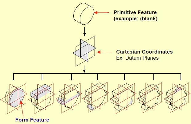
The simplest explanation I can give for it is this: You create a base feature, and bunch of datum (working) planes. You attach all the child features to those datum planes. Viola: no parent-child problems.
I admit that I’m not going to do justice to horizontal modeling in this conversation. There’s actually quite a bit to it, and it makes a lot of sense when coupled with computer-aided process planning (CAPP.)
Horizontal modeling has a handful of problems. First, it does a pretty good job of killing the possibility of having design intent expressed in the feature tree. Next, it works better with some CAD systems than others. (When horizontal modeling was in the news, SolidWorks had a problem managing the normals on datum planes, so it didn’t work too well.) The deadliest problem is that Delphi got a bunch of patents on the process, then licensed it to some training companies. From what I can see (and I may be wrong), none of these training centers offer horizontal modeling classes any more.
While, technically, you can’t use horizontal modeling without a patent license from Delphi, the concepts at its core are fairly similar to things that CAD users have been doing for years. A few years ago, Josh Mings posted on a couple of online forums that “Horizontal Modeling is just one word for it, you may also know it as Skeleton Modeling, Tier modeling, Sketch Assembly modeling, CAD
Neutral Modeling, or Body Modeling.” (It’s actually two words for it, but I get his point.)
Horizontal modeling is not a silver bullet solution for the problems inherent in parametric feature-based CAD. It’s just a best practice—a strategy for getting around the problems. It seems to be headed in the right direction, but it suffers from the complexity that comes from trying to fix too many problems at once.
Next: A Resilient Modeling Strategy
I was also thinking that horizontal modeling could be reduced to “reference everything to the main model datum planes”, but wouldn’t this make the model absolutely “dumb”? I mean, in the depicted example, if one wants to enlarge the main cylinder all other “features” would not update, and you’ll have to change everything by hand, or put some “relations” in the model to account for that, but adding relation is exactly what parametric CAD modeling is for.
You’re right on the mark. There is a trade-off between dumbness, and complexity. One of problems of completely flat models is that they don’t really encapsulate design intent. But, sometimes it might be easier to keep your design intent external to the model, to allow flexibility in editing. Just because something is “dumb” doesn’t mean it’s bad.
The biggest problem IMHO is that designers (modelers?) do not think, just go doing things and adding features. What is related to what is the root of the parametric modeling. I am a dumb sometimes and go crazily adding features, in the end the model is a mess, but then I have an idea of what I want. Then I come back and redo everything in the proper way that the model is fully parametric and easy to work with
Nothing new here. Caterpillar and other companies that work with very large assemblies have been “hanging” things off the default coordinate system for decades. It has its advantages and disadvantages, mostly disadvantages when it comes to geometry modeling. Design intent is critical; without it what could be an well balanced and elegant meal is reduced to mess hall hash.
A little annoying to find that the conclusion is that doing good CAD design is hard and requires planning and exercise. Some get it, some don’t; not every engineer who is a good engineer will be good at CAD design.
Also annoying to find that this is less an article than an advertisement for Siemens’ training division.
“Horizontal Modeling” does not require a patent license to employ. I personally was teaching those techniques in SDRC long before those guys came on the scene. I really tire of hearing this meme out there.
That said, it’s a good technique! Using it in the extreme to isolate each feature to datums is often quite painful and excessive. Best case use is to localize portions of the model and their features to balance dependencies vs design intent for a model that can endure significant changes. Some systems have better capability than others too.
Parametric modeling is not a failure at all. For many well defined parts, assemblies and their families, parametric modeling can and does deliver high productivity and accuracy and consistency.
It’s just not well indicated for all design workflows.
Direct modeling used to be a very basic thing, dependent on the user to understand what they want to change, visualize that change, boil that down into some direct edits and creates that realize said change, then verify the change meets requirements.
Today, implementations of it vary, but the general innovation is both smart code to “parse” the model, optionally apply both selection and intent rules to help define and govern the impact of the change, and a hybrid history based, non history based mode of operation.
Siemens NX is a hybrid modeler that offers parametric modeling, direct modeling in the form of “Synchronous Technology”, and it does so with either a model history or not. This array of choices means a user can identify the technology workflow best aligned with the data they have, which may be “dumb” data from a foreign system, or “smart” data, and they may choose to directly edit it, or apply history to it, parameterize it even if it’s dumb, then proceed to change and or author new features.
Additionally, hybrids exist in another form and that is solid / surface modelers capable of operating on most *any* data, starting from wireframe, through surfaces and including manifold solid modelers. Siemens NX is a hybrid in this sense too.
The product of that is being able to use any source data and a full set of workflow options to realize new models, perform advanced re-use, and perform edits that all would be time consuming on systems that lack flexibility in how the problem is approached.
In this context, Parametrics remain a potent tool in the tool box that perform well when indicated and properly employed, while direct modeling and the option of model history or not satisfy many niche, “one off” and complex edit on native / non native data cases, which are poorly indicated for Parametric only solutions.
Cross CAD design and general 3D model reuse is considerably improved in this scenario where the source data may not be a solid, or may simply exist in a legacy system that would typically require a “remodel” or “redraw” task to be completed prior to the real engineering work that adds value and drives innovation.
Other vendors appear to be aligning with Siemens in their various implementations of Direct Modeling technology. The most important thing to consider when parametric modeling isn’t delivering results is whether or not the actual workflows possible and types of data to be operated on are well supported in tandem with Direct Modeling technology under consideration.
Failure to do this will see the adoption of Direct Modeling and some gains on whatever niche cases happen to fit, but a general loss due to lack of integrated workflow choices and or integrated secondary operations such as CAM, CAE, Inspection, etc…
As CAD continues to mature, systems change, requirements escalate, the need for robust workflow options –inclusive ones that allow for the kinds of things people really need to do will only increase. The smart money is on software that doesn’t dictate how things get done, focusing more on making things more possible to get done and how that work product can flow through the enterprise in a productive, informative way.
Regarding assemblies, constraints, datums, etc…
The dominant mode for larger scale projects is to “design in place” where a coordinate system heirachy is used to locate components relative to origins that make sense in the context of the project.
Assembly operations involving constraints are great where there are families of assemblies and or potential for significant changes that would require component positioning. The cost of this is considerable as the 6 degrees of freedom become increasingly burdensome as component count and product complexity increases.
Additionally, a multi-CAD world can benefit from a neutral object representation, such as JT which is the geometric product definition, including PMI (model based definition, 3D annotation, etc…), where the actual origin CAD system varies by vendor. Design in place capability is a key enabler to these kinds of advanced approaches seen today in military applications, aero and auto.
Given this context, Direct Modeling capability is a huge gain in that components can be reused, positioned, optionally constrained as needed, modified and added to regardless of what system they were originally modeled in. Parametric design isn’t well indicated for this, and in that sense “failed” on projects of considerable scale in number of components and complexity of components, leaving Direct Modeling to fill the gaps and carry us forward to bigger, better, faster projects.
It’s not a panacea folks. Nothing is. Consider your options carefully and make sure you look beyond just having the option to Direct Model for best case use of the technology.
Nicely written.
I guess I still need to clarify: I’m not saying that parametric modeling has been a failure. I’m saying that the promise of easy editing of parametric models has never been a failure (or, at least, never fully realized.) In too many cases, it’s still too hard to modify parametric models.
Side note: The further a part is from its origin, the greater the numeric error in calculations, particularly in things such as surface intersections. I’m curious if the major geometric modeling kernels actually normalize their calculations to deal with this problem?
No worries Evan, and thanks. I think you and I met once at some Solidworks “training” event where they were trying to get us to perform smoke and mirror demos. If this is you, I recall neither of us did well with that. :) Hilton, California, mid 90’s.
Anyway, I understand where you were going with that. But, I sort of enjoyed riffing on this topic and thought it might add some value.
It is my opinion that easy editing of parametric models won’t ever happen, sans some deliberate workflow / create constraints. There are just too many ways to tie things together. I suppose bigger and bigger code bodies capable of parsing this and presenting rational choices will continue to chip away at the problem, but a model is a model and when we put the math and intent in there, somebody else has got to understand it, or edits will be an issue. This is just an artifact of the technology.
I am a strong advocate of flexible workflow systems and hybrids for these reasons. Data is not always clean, and sometimes it’s abstract and that can be very useful as opposed to models that are strictly real world representative. That’s older school “CAD” as opposed to newer school “solid modeling” and a key point of friction with me and mid-range systems, most all of which appear to ignore “CAD” in favor of “models.” While this does keep the process clean and focused, it’s very limiting should the user want to solve problems outside the scope of intended functionality. Analytic geometry is very useful, though an increasingly forgotten art it seems. I could go on for some time about that where UI paradigms abstract away key inputs, which make things easy for the user who isn’t familiar with geometry and higher math, but it’s limiting and difficult for the ones who are. Suppose they could use MathCAD or something, but why bother with that when the CAD system has the goodies right there? Never could figure that one out…
So then, in the case of a “rats nest” parametric model, we are faced with not editing it at all, perhaps globbing on some new feature, or linking it into a new part where it can be modified in simple ways, sans that messy history.
Or we can “plug and chop” the edits in, adding more to a messy history, or in a system that offers it, strip the history and carry on from there.
Direct modeling can be done in a history based way in some software, so there is that choice too, globbing on some direct operations to avoid complex edits. This isn’t sustainable much of the time, but can be a great quick fix depending.
I’m a big fan of the “history based direct modeling” option more than I am “non-history based direct modeling” simply because it allows for both sequential parametric modeling and variational parametric modeling, something SDRC started to do, but never realized, though Siemens did carry that work forward in NX today.
Frequently, I will take a dumb solid, parametrize parts of it, then make changes, then add features. This is very useful to do, and it can then very quickly drop into an assembly and perform much like fully parametrized models do.
The analogy is assemblies where the pressure is to fully constrain, but the reality is no constraints or partial constraints are most often more practical and productive. It’s a shame to resolve so much and have it not really see changes.
In the better assembly systems, it is possible to mix design in place with some fixed components and coordinate systems upon which localized networks of constraints can deliver good value where changes happen, or are anticipated to happen. A hybrid approach that is flexible. Should things need some adjustment, all of that can be modified while not having to manage the entire assembly constraint network, making bigger things possible and practical on the computers we have today.
Flexibility is key here because a user may find the constraints sufficient, or they may not, or they may be missing as they were not anticipated to add value. So they can move, check, constrain optionally, and continue on with few worries.
So then, at the part level moving this direction makes a lot of sense as complexity goes up, give people robust options and they can use workflows that make sense rather than have to reverse engineer a rats nest, or perhaps give up a lot just to make a simple change rational.
That is an interesting observation about the tolerances and distance. Whether or not the kernels normalize things is maybe not exactly the right question to ask. The kernel is going to compute what it is given, and in that sense, how the system built around the kernel presents the problem very likely is closer to the right question to ask, though I could be wrong about it.
(and I shall ask it too, because it’s a great question)
Until then, I suspect how features are constructed impact this. Sketches for example have localized sketch coordinate systems, and some systems offer both localized coordinate systems as well as part coordinate systems, and this difference impacts how robust and flexible design in place really is. Of course, ideology has something to do with this as well, where exposing those to the user for direct manipulation isn’t done, or is done in a very general way to enforce using constraints…
(a mistake, if you ask me)
I guess I am saying there is normalization in most cases, I just don’t know when it actually is done.
Many systems will expose the modeling tolerances, and on those perhaps little is done, or they recognize the user may well have to manage that tolerance. Others make it dynamic, hiding it all in some attempt to simplify the user experience, or they believe it simply does not add value. “It should just work” kind of thing.
In NX, as well as SDRC, my two systems of choice right now, design in place can happen in two ways:
One way is to map the part local coordinate to the absolute origin, resulting in the actual part geometry being positioned away from the origin. When that file is opened, a part will be found “where it was made” away from the absolute 0,0,0.
The other way is to maintain a transform relative to the absolute origin, or another one that makes sense say in a sub-system, leaving the part close to it’s origin. When that file is opened by itself, the part is seen basically at the origin.
Either one is possible, and the trade-offs vary based on both neutral file representations and or downstream operations. The most common on larger projects is to have the parts be located absolute, though that isn’t the rule. Tolerance impacts are not something I’m hearing much about, so something is done for sure, I just don’t know what, but I do know the NX and SDRC products are capable of either paradigm and function equally well in either case.
Downstream operations, such as CAM, can be done “in place” as well with a manufacturing coordinate system used to move the machine to the part.
I currently am working for a VAR, in the Siemens channel and missed SE University this year. I’ll get the goodies soon enough.
Much of what I have written involves higher end CAD. I’m there because that is where the edges of this stuff are, and I do abstract geometry as much as I do real world representative things. That said, Solid Edge has implemented direct modeling in a lean way that combines sequential parametric and variational design in such a way that users will find it transparent. This is a great path, and the idea that we keep people focused on mechanical problems is a good one indicative of just why we have mid range and high end software offerings.
Very curious to read their take on the “horizontal modeling” attempt, and I’m sure you will do it justice to your readers in good time as well.
You know what strikes me as an opportunity not being fully exploited right now is ongoing work to communicate dependencies in ways users can more quickly understand and then manipulate.
When we do sequential parametric solid modeling, we are basically programming. That’s “design intent” at the core, and it isn’t an easy task. Now, we’ve abstracted that away into features, geometry, relationships, and that’s good on forward create, but it’s not so good on edit, where we basically take users to the place where it happened and that makes it out of the full context by definition.
Programmers suffer these same kinds of problems. Somebody writes code, and then somebody else needs to modify it, add to it or reuse it.
Their solutions mirror our struggles in CAD. They compartmentalize things, they abstract things, localize things. On create, many languages have evolved to simplify creation, and the implication is simple to write and simple to read = simple to edit, when the truth is complex dynamics are just complex. No getting around that, unless we want to limit the kinds of dynamics people are capable of expressing in software.
That’s not gonna happen.
It’s my opinion that we could be doing a lot more work to better visualize and or represent these model relationships. Programmers will do it by writing scrips to parse and visualize code, or they make maps of data, etc… whatever they can do to understand what is really going on.
So often, we are given terse lists of dependencies, can walk through them one at a time, and stuff highlights here and there, and those things help us to understand each piece, but the work to understand the whole is still drudgery at the least, and merely tedious and time consuming at best!
Direct kind of avoids this, but only for a time. As more variational solutions get incorporated into Direct modeling, understanding those relationships will maybe not have the burden of history, depending on how people do things and what options vendors offer them to work with, but there will still be complex dynamics and where that’s true, edits will remain painful, or we will continue the tradition of surrendering information in order to make the needs today easier, meaning an investment in the past doesn’t deliver a return.
In that sense, the work wouldn’t be wasted. Both modeling paradigms would benefit from more robust ways to understand the state of the model and maybe even suggest changes, or at the least make selecting edits, or possible edits quick and easy to vet, speeding up empirical methods at the least.
I’ve read about code reuse for years, and it all varies in it’s success. A whole lot of reuse in code comes down to standards and where standard or common data representations and logic representations can be employed, reuse stands a chance of happening.
The cost is flexibility, and the real world ends up being a balance between getting it done now, and right for the moment, or making investments for an unknown future, no different than what we struggle with in CAD.
To carry the analogy just a bit further, the best programmers are flexible ones, able to use multiple languages and work in various ways to resolve the problem. Software engineers struggle with the same thing mechanical ones do in this regard. The best CAD users are those who understand multiple workflows, data managers, systems, etc… and who can work in various ways to get things done.
What gets both camps into trouble is both limits in the software due to ideology / design decisions that limit options today, and the user religion of “this is best” which can often translate into “this is what I know” two different things as we all well know.
Task / package focused education only makes this worse! Vendors leverage that and UI paradigms to lock people in, and the people like reusing skills and resist change because that takes time and energy away from the task at hand, and managers / companies consistently fail to value regular investments in people and technology as the gains they can be, right along with planning and analysis, favoring the “get it done now” pushing a lot of the work into the future, always the future… never today.
I don’t really expect vendors to adopt a more robust training model. They are task / product focused and probably always will be. However, educating people on the higher level points of this discussion can and should be an emphasis in both primary education where CAD may well be and should be present just as programming can and should be, as well as secondary / higher education, where it’s often funded by vendors looking to increase share, and depending on the vendor, may not support the robust and inclusive kind of education needed to improve things.
Should that begin to happen, user demand for options outside the bells and whistles, and that ever present “make it easy” button, may well drive better software and we all would benefit.
Note the discussion here and elsewhere and how it’s so often colored by the systems people have used. It’s actually quite difficult to express things in a general, more academic way and that does nobody any good, IMHO of course.
We get spoiled, don’t we. I remember not too many years ago, that it was so cumbersome to add fillets to a model, that I skipped the the exercise whenever possible, then put the fillets in the part as part of tooling selection in the CAM programming.
Today, I modeled a cover with dozens of intersecting ribs, and structures. It took a little time to sequence the fillets to get them right, but completely doable, and manufacturable. I doubt the vendor will give them much thought, or have the slightest difficulty in programming for the mold. At one point the client asked to have some mounting points moved. I had created a design intent that allowed for adjustment. One dimension change, and the part was updated. How many times, in years past would that have caused lost hours, if not days?
Solid modeling complex parts is hard. It’s hard to design with the end in mind. It’s hard to think of ways to link features so that they can remain parametric. It’s easy to miss one relationship, and experience feature tree meltdown with a change. I doubt parametric modeling will ever be completely free of these challenges. Still, with all that, it is a heck-of-alot easier than it used to be.
I feel that we, as a CAD community suffer from “ease of use”. It is so easy to window select everything and hit “fillet”. Moving and modifying is so easy. So easy in fact, we dont always realize the ramifications. Back in the day, when we did things on a drafting board, you had to physically calculate changes and you would see first hand the consequences of our mods. “I have to move this hole…oh, that pocket is dimensioned to that hole. Oh and that slot is dimensioned to that pocket. I will have to erase and redraw all of that.”
I think the time has come to implement some best practices that help us CAD Monkeys to create models that others can understand and modify. Unfortunately this may take away a little “ease of use”.
Siemens employs a tight system tolerance, and they’ve optimized around that.
Users can adjust the tolerance, if they are aware of the problem. Additionally, Synchronous includes “optimize face”, and there are some surfacing options, such as “match edge” to deal with ugly cases.
Siemens also has a bounded modeling area equal to one Kilometer. Users can override that if a model requires it.
Seems to me, they tackled the problem by putting a reasonable boundary on it, optimizing for that and giving users tools where their use cases may exceed the optimal scenario Siemens builds for.
All in all, this is likely a reasonable performance / accuracy / reliability balance.