• Skip to primary navigation
  • Skip to main content
  • Skip to primary sidebar
  • Skip to footer

3D CAD World

Over 50,000 3D CAD Tips & Tutorials. 3D CAD News by applications and CAD industry news.

  • 3D CAD Package Tips
    • Alibre
    • Autodesk
    • Catia
    • Creo
    • Inventor
    • Onshape
    • Pro/Engineer
    • Siemens PLM
    • SolidWorks
    • SpaceClaim
  • CAD Hardware
  • CAD Industry News
    • Company News
      • Autodesk News
      • Catia News & Events
      • PTC News
      • Siemens PLM & Events
      • SolidWorks News & Events
      • SpaceClaim News
    • Rapid Prototyping
    • Simulation Software
  • Prototype Parts
  • User Forums
    • MCAD Central
    • 3D CAD Forums
    • Engineering Exchange
  • CAD Resources
    • 3D CAD Models
  • Videos

CAE

Parameterizing CAE models with COMSOL

June 7, 2012 By Evan Yares 1 Comment

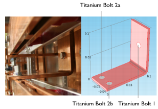
COMSOL ParametricsAltaSim Technologies is a COMSOL certified consultant, offering consulting, training, and concept development. Essentially, a bunch of smart people who know how to do CAE right.

Every once in a while, AltaSim sends out a tips & tricks email. Here’s one that caught my attention:

Unless you know for sure (like 100% sure) that you won’t need to change any dimensions or geometric features of your model at any time along the way, it is beneficial to take the time up front to Parameterize your geometry. With parameterized geometry, complicated and otherwise time-consuming geometry updates can be made in a matter of seconds. In addition, a COMSOL solver sequence can sweep in parameter space over a geometric parameter.

Time-savings could be your biggest benefit with this tip. Think of how time-consuming it would be to change your model from 3 coils (bends) to 6 coils (bends), for example. But with Parameterized geometry, you are only a few mouse clicks away from updates when dimensions or features change. Depending on the complexity of your problem and the number of changes, this could be hours of time savings. It may be tempting to save time initially by parameterizing only the geometry you anticipate could need changes, but once we start looking at results we find ourselves changing other dimensions as well.

This is an example of something that sounds pretty simple on the surface, but requires a bit of thought to do right.

The first question that occurs to me is which model do you parametrize: The design (CAD) model, or the analysis (CAE) model?

The second question is how do you parameterize it?

In integrated parametric CAD/CAE systems, such as SolidWorks Simulation, the analysis model is a configuration of the design model, with insignificant features turned off. The parameters are already there, and can be used directly for CAE optimization.

COMSOL can certainly be used with CAD model based parameters. But it also supports its own parameterization tools. It’s possible to read in a CAD model (from any source) as a dumb solid, simplify it to create an analysis model, then parameterize that analysis model, in a manner that represents your design intent, and lets you properly optimize the model.

Which way is better? It’s a workflow issue. You do it whichever way is fastest. If you can automatically regenerate the analysis model from the design model, then it makes sense to use the design model’s parameters. If the process of generating the analysis model from the design model is time consuming, and requires manual work, then you should probably parameterize the analysis model.


Filed Under: CAE, Evan Yares Tagged With: AltaSim, CAE, COMSOL

Autodesk provides real-time DFM for plastic part design

April 3, 2012 By Evan Yares 1 Comment

There’s a lot of benefit to be had by doing manufacturability analysis (DFM, Design for Manufacturing) early in the design process, rather than waiting until later, when design changes are far more expensive.

A couple of years ago, Autodesk Labs previewed a product, Project Krypton, which ran inside of 3D CAD programs (including Autodesk Inventor, DS SolidWorks, and PTC Pro/E), and gave real-time feedback on manufacturability, cost, and sustainability of plastic injection molded parts.


Project Krypton has now reappeared, in commercial form, as Autodesk Simulation DFM (Design For Manufacturing.) It works as a plug-in, running in a number of versions of Inventor, Inventor LT, Wildfire, Creo, and SolidWorks. It is available as a subscription benefit for Autodesk Simulation Moldflow Adviser 2013 subscribers, or as a stand-alone product, at US$2,000 for a license to run on any of the supported CAD platforms.

It’s reasonable to argue that engineers who are designing plastic parts should know enough to be able to recognize manufacturability, cost, or sustainability problems. And, if they don’t, they should take the time to learn (for example, by taking a few hours to read any of the many freely available books on the subject, such as General Design Principles for DuPont Engineering Polymers.) Even though that argument is reasonable, it doesn’t recognize human nature. People, even engineers who should know better, don’t always take the time to “read the manual.” Often, it makes sense to build the “manual” into the tools that engineers use every day. Simulation DFM does that, and quite a bit more.

For inexperienced designers, Simulation DFM provides quick feedback to help them avoid rookie mistakes. It’s sort of like an “idiot light” on a car’s dash, that warns you when something is wrong. And while old-hands might say they prefer gauges to idiot lights, experience has shown that idiot lights are useful to experts (even F1 drivers and fighter pilots) for catching their attention, and getting them to actually look at the gauges.
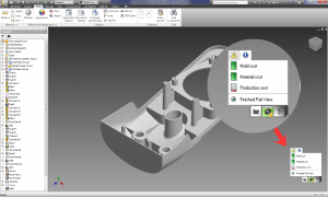
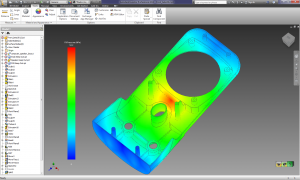
Simulation DFM doesn’t require that users have any background in molding simulation. It uses “green is good, yellow is not so good, and red is bad” indicators to identify potential manufacturing, cost and sustainability issues, showing the source and location of the problem. Any issues that pop-up can be expanded upon, to provide more detail on the exact source of the problem, even showing, for example, mold filling analyses.  The software requires no additional training, and doesn’t require much user input.

The open question with Simulation DFM is “how good is it?” Since it’s based on the Autodesk Moldflow simulation engine, it should be quite good, even for relatively complex parts (though it doesn’t support multi-body parts.) Yet, even if its capabilities were modest, it would still be of value, in either helping beginning designers to learn good design practice, or helping old-hands catch mistakes they might have otherwise missed.

As an engineer, I’ve long had the habit of using the “anything I can see” test to evaluate the usefulness of software. I look around the room, looking at anything I see, and ask myself “would this software have helped the engineers who designed these things?” In this case, as I sit in my office, I can see at least 20 items (without even turning to look behind me), each with multiple injection molded parts, that would have been quicker, easier, and less-expensive to design, had their engineers had access to up-front DFM software, such as Autodesk Simulation DFM.

The most significant benefit of Autodesk Simulation DFM comes not from its detailed capabilities, but rather from its clean integration into the design workflow. A user need not press a button, or take any specific action when designing a plastic part to benefit from it. All they need to do is notice, as they design, whether the software has picked up any obvious red-flags.

That Autodesk decided to make Simulation DFM available for Pro/E, Creo, and SolidWorks (as well as Inventor) shows that rational minds sometimes do prevail: There are untold thousands of PTC and SolidWorks customers who design plastic injection molded parts, and who are unlikely to switch primary CAD tools any time soon. The challenge Autodesk is going to face is in getting Simulation DFM in front of those users (since PTC and SolidWorks sales reps and dealers are not likely to recommend it.) Maybe not so much of a challenge: Many of Autodesk’s existing Moldflow customers are Pro/E and SolidWorks users.

There’s a certain charm to software that does something of great value, but does not impose any extra demands on its users. Autodesk Simulation DFM looks like it may be that kind of product.

Autodesk www.autodesk.com

Autodesk SimSquad simsquad@autodesk.com

Filed Under: Autodesk, Autodesk News, Creo, Evan Yares, Featured, Inventor, News, Pro/Engineer, Simulation Software, SolidWorks Tagged With: Autodesk, CAE, Creo, DFM, Inventor, Moldflow, Pro/E, simulation, SolidWorks

Hot rod engineering workstations

February 20, 2012 By Evan Yares Leave a Comment

When I was barely a teenager, in the early ’70s. I became interested in car magazines. In the back of some of those magazines, I’d often see ads for a company called Baldwin/Motion Performance. They sold brand new hot-rodded Camaros that were guaranteed to run 11.50 second or faster quarter miles at the drag strip. Baldwin/Motion Performance Camaros represented the epitome of tuner-built hot rods. They were fast enough that, according to Super Chevy magazine, you could buy one, and, with no further tuning, win the A/MP class at the Winternationals.

During the same period, other companies also sold fast Camaros. Though GM’s official policy in the late 60’s and early 70’s was that they didn’t support drag racing, there was a way to get nearly drag-ready cars, if you knew the trick. A few dealers, notably Yenko Chevrolet, managed to get Chevrolet to install Corvette 427ci L-72 engines in Camaros, through the “central office purchase order” process. These factory hot rod COPO Camaros came with a full factory warranty. Nearly perfect examples have sold for over $2.2 million USD at auction.

Muscle cars have little to do with CAD, but I was reminded of these cars, at least by analogy, when I was at the SolidWorks World 2012 show, in San Diego, last week.

While there, I attended a press conference announcing HP’s new Z1 engineering workstation. This machine is sort of analogous to a factory hot rod. It comes with a stunning 27” built in display, a quad-core Intel Xeon processor, NVIDIA Quadro graphics, and uses ECC (error correction code) memory—which is particularly desirable for critical engineering software applications (See Wikipedia’s entry on ECC memory for background on this.)

There’s no doubt that the Z1 costs more than a typical commodity PC. But, for people doing serious CAD, CAE, or CAM work, the performance and reliability the system offers is worth the premium.
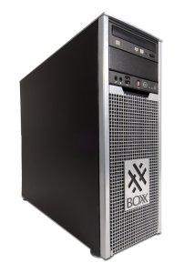
While at SolidWorks World, I also had a chance to chat with Rick Krause, CEO of BOXX Technologies. BOXX makes what could be considered the equivalent of a tuner-built hot rod. Their 3DBOXX 3970 XTREME workstation is designed to provide the best performance possible for serious 3D CAD work. That is, it’s performance isn’t tuned for doing spreadsheets and web browsing (which benefit from multiple core processors), it’s tuned for doing serious CAD work (which requires fewer, but faster cores.)

Let’s go back to the car analogy: Yenko Chevrolet sold stock Camaros, with the biggest and best engines GM offered. Baldwin Chevrolet sold hot-rodded Camaros, also with the biggest and best engines GM offered, but tuned to put out over 500+ horsepower (while still being streetable.)

The HP Z1 engineering workstations use Intel’s biggest and best processors. The BOXX XTREME workstations also use Intel’s biggest and best processors – tuned (overclocked) for the most horsepower.

BOXX doesn’t really like to use the work “overclock,” because it implies that they’re pushing the processor past it’s design spec. BOXX works closely with Intel, to make sure they stay within the processor design specs. Since they use liquid-cooling, they can push the processor faster, without reliability problems. Their workstations are backed-up by a 3 year warranty, and, in their history of selling overclocked systems, they’ve never experienced a processor failure.

If you’re a serious CAD, CAE, or CAM user, and you can out-run your current computer, you need to take a serious look at getting a factory-built or tuner-built hot rod computer.

HP Z1 Workstation

BOXX Technologies 3DBOXX 3970 XTREME Workstation

 Photo courtesy Baldwin-Motion


Filed Under: CAD Hardware, Evan Yares Tagged With: BOXX Technologies, cad, CAE, cam, Engineering Workstation, Evan Yares, HP

Screaming workstation

February 17, 2011 By Laura Carrabine Leave a Comment

The BOXX 8550 Xtreme is a dual processor workstation well suited for design visualization specialists or CAD/CAE software users who need a system to perform multiple simulations or toolpath calculations at the same time.

A test machine featured two Intel Xeon X5680 processors, but instead of the 3.33GHz clock speed they usually run at, both chips have been overclocked to an 4.2GHz. Naturally, this creates a lot of heat and a sophisticated liquid cooled sub-system is used to keep them running within their thermal limits.

The result of having two Xeon chips run at such speeds is an exceptionally fast workstation. It recorded the fastest ever time our 3ds Max benchmark, using its 12 physical and 12 virtual HyperThreading cores to full effect, rendering the test scene in 96 seconds.

It also made light work of our PowerMill CAM test, setting new records when running two and three tests concurrently.

The BOXX 8550 Xtreme is also well equipped in the graphics department. The 2GB Quadro 4000, one of Nvidia’s high-end Fermi graphics cards, recorded impressive results in our SolidWorks graphics test.

Storage is a little underwhelming for a machine of this caliber, comprising one 160GB 2.5” 7,200RPM SATA hard drive for operating system and applications and a 500GB drive for storage.

However, optional Solid State Drives (SSDs) are also available in sizes of 60GB – 256GB. All drives are tucked behind the motherboard.

BOXX Technologies

www.boxxtech.com

Filed Under: 3D CAD Package Tips, CAD Blogs, CAD Hardware, SolidWorks Tagged With: 3D, Boxx, cad, CAE, Intel, Power Mill CAM, Xeon

CFD Updates

February 17, 2011 By Laura Carrabine Leave a Comment

Pointwise announces the latest release of its Pointwise computational fluid dynamics (CFD) meshing software with a set of new tools.

The surface meshing formulation of the T-Rex (anisotropic tetrahedral extrusion) hybrid meshing algorithm first developed for Pointwise’s Gridgen software now is available in Pointwise version 16.04. At the other end of the meshing spectrum, a new tool has been added for moving individual grid points. Other notable new features include the ability to split and join faceted geometry models and the extension of the CAE plugin API for writing your own CAE solver export to structured grid formats.

The new release also includes 64-bit support on Mac OS X, annotation entities, printing to PNG, TIFF, and BMP files, and 11 new or updated CAE software interfaces.

Pointwise, Inc. is solving the top problem facing engineering analysts today – mesh generation for CFD. The company’s Gridgen and Pointwise software generates structured, unstructured, and hybrid meshes; interfaces with CFD solvers, such as ANSYS FLUENT, STAR-CD, ANSYS CFX, and OpenFOAM as well as many neutral formats, such as CGNS; runs on Windows (Intel and AMD), Linux (Intel and AMD), Mac and Unix, and has scripting languages that can automate CFD meshing.

Pointwise, Inc.

www.pointwise.com

Filed Under: Simulation Software Tagged With: ANSYS CFX, ANSYS Fluent, CAE, CFD, Open Foam, Pointwise, Star-CD

Superconducting wire and CAD tool vendors combine forces to simplify electrical machine design

August 4, 2010 By Laura Carrabine Leave a Comment

Cobham’s QUENCH electromagnetic software tool for modeling the quenching process in superconducting materials now comes with a library containing comprehensive manufacturer-supplied material characterization data for Sumitomo’s DI-BSSCO bismuth-based superconducting wire. The combination will simplify the design and prototyping stages of applying high temperature superconductors (HTS). Among the application sectors currently exploring HTS-based solutions are electricity transmission and distribution infrastructure, hydroelectric and wind turbine generators, electric motor propulsion systems for ships, and high performance magnets.

Sumitomo Electric was the first company in the world to produce long bismuth-based superconducting wire, a material that has become an industry standard and is considered to be the major candidate for commercial HTS applications. Sumitomo’s bismuth-based superconducting wire – DI-BSSCO – is made of bismuth-strontium-calcium-copper-oxygen and operates at temperatures up to 110 K. Sumitomo’s BSSCO materials have been used in pioneering superconducting applications for almost 20 years, including the world’s first superconductor electric vehicle, the first underground in-grid cable, transformers for high speed trains, and windings for ship propulsion motors.

The QUENCH tool for modeling the superconducting “quenching” process – when a wire turns from a superconducting to resistive state – is available as part of Cobham’s Opera CAE software suite for low frequency electromagnetic simulation. QUENCH has become the standard simulation tool for superconducting equipment because of its sophisticated multi-physics modeling which couples the electromagnetic and thermal modeling processes. Results can be post-processed to provide users with clear views and analyses of the potentially damaging effects of quench propagation as the wire heats up and becomes resistive including displays of the voltages between coil layers, temperature gradients, and so on. This analysis helps users to find the optimal design and incorporate protection circuitry.

Sumitomo Electric Industries, Ltd.
www.global-sei.com

Cobham Technical Services
www.cobham.com

Filed Under: 3D CAD Package Tips Tagged With: CAAD, CAE, Cobham, Di-BSSCO, Multiphysics, Quench, Sumitomo, superconducting

Primary Sidebar


3D CAD NEWSLETTERS

MakePartsFast

Follow us on Twitter

Tweets by 3DCADWorld

Footer

3D CAD World logo

DESIGN WORLD NETWORK

Design World Online
The Robot Report
Coupling Tips
Motion Control Tips
Linear Motion Tips
Bearing Tips

3D CAD WORLD

  • Subscribe to our newsletter
  • Advertise with us
  • Contact us
Follow us on Twitter@3DCADWorld
Add us on FacebookDesign World Network
Add us on LinkedInLinkedIn
Add us on InstagramInstagram
Add us on YouTubeYouTube

3D CAD World - Copyright © 2019 · WTWH Media LLC and its licensors. All rights reserved.
The material on this site may not be reproduced, distributed, transmitted, cached or otherwise used, except with the prior written permission of WTWH Media.

Privacy Policy