• Skip to primary navigation
  • Skip to main content
  • Skip to primary sidebar
  • Skip to footer

3D CAD World

Over 50,000 3D CAD Tips & Tutorials. 3D CAD News by applications and CAD industry news.

  • 3D CAD Package Tips
    • Alibre
    • Autodesk
    • Catia
    • Creo
    • Inventor
    • Onshape
    • Pro/Engineer
    • Siemens PLM
    • SolidWorks
    • SpaceClaim
  • CAD Hardware
  • CAD Industry News
    • Company News
      • Autodesk News
      • Catia News & Events
      • PTC News
      • Siemens PLM & Events
      • SolidWorks News & Events
      • SpaceClaim News
    • Rapid Prototyping
    • Simulation Software
  • Prototype Parts
  • User Forums
    • MCAD Central
    • 3D CAD Forums
    • Engineering Exchange
  • CAD Resources
    • 3D CAD Models
  • Videos

CNC

In-House Prototyping: 3D Printer or CNC Machine?

July 16, 2014 By Barb Schmitz Leave a Comment

Physical prototyping of parts has traditionally caused major bottlenecks in the product development cycle. Though somewhat of a necessary evil to build physical prototypes for testing, the process by which they are created causes significant delays in development and drives up over design costs.

Traditionally when design teams need a part prototyped, they outsource it to third-party job shops. Since outside job shops typical have minimums in terms of order quantities, these prototypes are not given high priority, slowing down their production. If designers want the prototypes turned around quickly, they are typically required to pay a premium.

New rapid prototyping technologies change the game

Increasingly sophisticated machining technology is becoming more affordable and accessible, and as a result, more and more companies are bringing technology, such as CNC machines and 3D printers, in house. Having the capabilities to create prototypes quickly in house saves significant time to market over the traditional process of outsourcing to machine shops.

The affordability of 3D printing is poised to radically change the landscape for manufacturing forever. 3D printing enables design teams, as well as hobbyists and would-be inventors, to quickly create physical prototypes with the push of a button. The prices of these machines and the materials they use have plummeted in recent years, putting the technology in the hands of anyone with an idea and a desire to convert that idea into a reality.
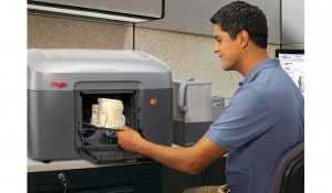
The Mojo desktop printer from Stratasys prints finely resolved models in nine colors.

Most designers and engineers recognize the value of being able to rapidly produce a physical component of their design, especially if it’s a complex design. They want to be able to hold it, pass it around in a meeting, and to know what it will feel like. It’s difficult to read anything today and not hear about the exploding popularity of 3D printing, but is it the best option for creating prototypes?

3D printer or CNC machine: Should it be an either-or proposition?

Anthony Graves, product manager at Autodesk, believes the answer to that question is not always. “Over the next couple of years, engineers are going to recognize that just like there’s value in having a 3D printer, there’s a tremendous value in having a CNC machine for the same reasons,” says Graves. “Sometimes you want to be able to produce the real part that’s going to be used, not just a representation of that part.”

For a simple smaller part, to create a 3D print might take a couple of hours, whereas with an integrated CAM app and a CNC machine, that same part could be produced in under 20 minutes. As a result, for many parts, it’s faster to machine them than to 3D print them. For parts that cannot be done economically or quickly on a CNC machine, designers should use a 3D printer.

“For prototyping, you shouldn’t choose between a 3D printer and a CNC machine, you should have both,” says Graves. “3D printing is all the rage, but it really shouldn’t be an either-or proposition because the two technologies complement each other. I could go out and for several thousand dollars buy a very respectable 3D printer with decent resolution, but I can also buy a bench-top CNC machine for the same amount of money.”

Barb Schmitz

Filed Under: CAD Hardware, News Tagged With: 3D printer, 3D printing, CNC, Rapid Prototyping

Giant sculpture created in 3D CAD

January 18, 2012 By Laura Carrabine Leave a Comment

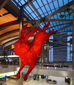
Whether they need a reminder that they’re late or welcome a distraction from the hassle of modern travel, visitors to Sacramento’s International Airport will not miss Denver-based artist Lawrence Argent’s Leap sculpture. Completed recently in the new Corgan Associates-designed Terminal B, the 56-foot-long red rabbit is suspended mid-jump in the building’s three-story central atrium. An oversize “vortical suitcase” placed in the baggage claim below completes the piece. Argent worked with California-based Kreysler & Associates, a specialist in the design, engineering, and fabrication of large-scale sculptural and architectural objects, to build his vision while meeting the airport’s safety requirements.

The team originally planned to build the sculpture with glass fiber composite, but fire codes would have required additional engineering studies to prove it was flame retardant. Additionally, the building was going to be largely enclosed by the time the sculpture was ready for installation, making it impossible to bring the sculpture, which is 14-ft wide and more than 16-ft high, into the building in one piece.

Argent had designed the sculpture as a form composed of hundreds of flat triangles. “The piece lent itself to aluminum as long as we could figure out how to fabricate the pieces,” said Bill Kreysler, who founded the fabrication company in 1982. Working with Argent’s digital renderings, Kreysler’s team translated the design into Rhino software, creating what he calls a semi-monocoque structure with a double-skin of thin aluminum on a thin-ribbed interior aluminum frame. The decorative surface is composed of 1,446 CNC-cut triangles with side dimensions ranging from one in. to three ft. Etched with a numbering system, the triangles were placed using laser-projected grid lines.

“I think that one of the things that is often overlooked in this digital fabrication world is that there’s a sense that because computers are controlling the process, the human element is reduced, but in many ways it’s increased,” said Kreysler, who limited the number of people working on the piece to ensure consistency.

The rabbit’s interior structure was assembled into 14 pieces of varying diameters in the shop, then transported to the airport for assembly. The exterior aluminum triangles are textured with crushed glass to create a velvet-matte surface and float 1½ in. above the interior shell with aluminum standoffs.

Even in the light-filled atrium space the sculpture’s suspension system appears minimal. The concentrated loads coming from seven custom wire rope suspension cables with swage fittings are received by the rabbit’s internal steel armature. Aluminum transverse members then distribute these loads from the steel armature to the monocoque aluminum shell.

Unveiled on October 6, 2011, the new $1.3 billion airport addition is the largest construction project in Sacramento’s history. The rabbit is the centerpiece of the 14 art installations—more than $6 million worth—commissioned by the city’s Metropolitan Arts Commission and planned for completion in the coming years.

Rhino

www.rhino3d.com

Filed Under: 3D CAD Package Tips, CAD Blogs, CAD Package, Design World, Featured, Make Parts Fast, Rhino Blogs Tagged With: 3D CAD, CNC, digital fabrication, Rhino, Sacramento

Orange County Choppers

September 29, 2011 By Laura Carrabine 1 Comment

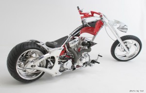
Orange County Choppers (OCC) started designing and building custom motorcycles in 1999. The company selected SolidWorks Premium software as its standard design platform because it is easy to use, includes visualization and surfacing tools, and integrates well with MasterCAM software which automates machining on the company’s HAAS CNC production systems.


“Every bike we build is a 100% custom design,” said OCC senior designer Jason Pohl. “With SolidWorks, we can refine the design and then control the production of parts with a high degree of precision. SolidWorks has become the backbone of our development effort because everything revolves around the SolidWorks model.”

Instead of trying out different concepts in the shop using actual prototypes, the company now iterates on designs in the SolidWorks design environment, which is more efficient and cost-effective. Since implementing the software, OCC has accelerated its time-to-market by 100%, cut design cycles by 75%, and eliminated several rounds of prototyping.

OCC can now efficiently handle the increased volume of orders it now receives, both in development and during production. SolidWorks support for automated machining boosts throughput and because manufacturing from a solid model is more accurate, OCC is able to keep its costs down. Since implementing SolidWorks, the custom motorcycle manufacturer has cut development costs by 50%.

Pohl added, “Whether we’re working with an outside vendor or in our own machine shop, SolidWorks makes it easier to efficiently create usable parts. In my experience, 2D techniques hide flaws. 3D design reveals flaws. When it’s time to manufacture a part, the software enables us to have confidence that the model is right. That makes our lives a whole lot easier.” 

SolidWorks also helps OCC interact more efficiently with customers, who often want to see how the motorcycle will look before placing an order, especially for a growing number of corporate bikes. Using the software’s visualization and communication tools such as PhotoView 360, OCC can show high-quality renderings of custom motorcycle designs to clients.

SolidWorks

www.solidworks.com

Orange County Choppers

www.orangecountychoppers.com

Filed Under: 3D CAD Package Tips, CAD Industry News, SolidWorks, SolidWorks Blogs Tagged With: 3D CAD, CNC, Orange County Choppers, PhotoView 360, SolidWorks

20th release of SolidWorks wins kudos

September 7, 2011 By Laura Carrabine Leave a Comment

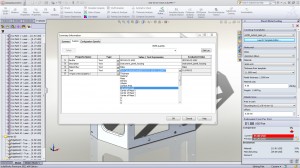
There are new drawing tools to help create better looking and more accurate images. For example, changed dimensions are automatically highlighted and show previous values to help with revisions. Sequential balloon ordering and magnetic lines automatically help order and position balloons. So you may not have to spend as much time detailing and aligning drawings.

SolidWorks’ Sustainability’s new user interface can be used to more accurately model products with “what-if” scenarios and custom materials. Users can model processes with parameters such as recycled content and duration of use. Access to the latest Sustainability supplemental materials will be instant and continuous as they become available.

The large design review allows instant opening and review of large assemblies or any individual component with walkthroughs, sectioning, and measuring without the need for a high-powered computer or special file preparation. The freeze feature eliminates unwanted feature rebuilds by locking all features above the “freeze” bar. This option can help speed up the design of complex models where rebuilding specific features is not needed. Features can also be unfrozen at any time. There are also new equation capabilities that speed up the calculation process.

Design costing is a tool that automates manufacturing cost calculations for sheet metal and machined parts. Designers can make more informed decisions based on cost throughout the design process and continually model new scenarios for instant up-to-the-minute manufacturing estimates. SolidWorks 2012 offers new sheet metal tools such as precise control of edge flanges, including up-to-vertex end conditions. Designs can be flattened and documented for manufacturing with export to CNC and manufacturing equipment.

SolidWorks Simulation includes enhanced motion optimization that automatically uses motion study results to create sensors and refine complex and time-intensive machine aspects such as motor size, bearing loads, and range of travel. Users can optimize designs quickly as they refine inputs and immediately see changes to restraints or goals.

SolidWorks Enterprise PDM has new support for Office 2010 and an x64 web client. In addition, there are enhancements to 3DVIA Composer including part-to-part shadows, ambient occlusion, and shadows to 2D panels with precise control. A glow effect can also be added to highlight specific areas of interest.

SolidWorks

www.solidworks.com

Filed Under: 3D CAD Package Tips, CAD Blogs, CAD Package, SolidWorks, SolidWorks Blogs, SolidWorks News & Events Tagged With: 3D CAD, 3DVIA Composer, CNC, Dassault, drawings, PDM, sheet metal, SolidWorks

Yar Golf has a hit with its Alibre-based putter

August 31, 2011 By Laura Carrabine Leave a Comment

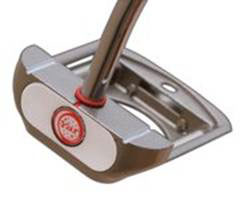
According to Gerri Jordan, Yar Golf’s president, “The GW1 putter is also tied for the number one spot in the categories for accuracy, alignment, and sound compared to putters that cost thousands of dollars more.”

The Yar Golf engineering team started using Alibre Design 3D CAD software to design the GW1. Jordan added, “We were able to acclimate the Alibre Design Expert and go from written theory to full testing prototype production in less than 90 days. Alibre’s product support is superior and always had the solution when we encountered an issue.”

The Alibre models were translated into CNC code for machining prototypes and eventually for production of a precision mold. An ISO-certified aerospace facility cast the putter heads in stainless steel. After rounds of testing, Yar Golf put the design into full commercial production.

The putter is also important apparatus in what is called by the USGA as Adaptive Golf for players with disabilities. The putter’s improved balance offers greater control for golfers with prosthetics. Even for players who have trouble bending over, the GX1’s wide footprint and circular openings can be used to pick up or place balls, markers, hole flags, and other clubs.

Alibre
www.alibre.com

Yar Golf
www.yargolf.com

Filed Under: 3D CAD Package Tips, Alibre, CAD Industry News, Company News Tagged With: 3C CAD, Alibre, CNC, golf, Yar Golf

Innovative tooling

February 24, 2011 By Laura Carrabine Leave a Comment

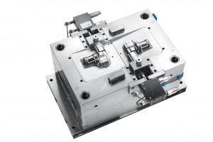
Kummer GmbH uses Vero CAD/CAM software for a variety of product development tasks. For instance, VISI Modeling is used for component design as well as for developing its punch tools. VISI Progress is used to develop the sheet metal component and strip layout. VISI Mold is used for the design of the plastic injection mold.

Once the tool design is completed, Vero’s Compass Technology is used in the CAD department for 2 and 2-1/2-axis CNC programs. The feature recognitiionn is ccapable of analyzing the 3D model for regular geometries such as holes, pockets, or T-slots. Based on the standard component type (screw, pillar, dowel) feature properties are applied during the tool design phase which are automatically picked up by Compas. That means a hole can be automatically recognized and machined regardless of its diameter, using a different sequence of CAM cycles.

Vero Software                             

www.vero-software.com

Kummer

www.kummer-gmbh.de


Filed Under: 3D CAD Package Tips, CAD Package Tagged With: CAD/CAM, CNC, Compass Technology, Kummer, Vero, VISI

Software reinvents the wheel

February 15, 2011 By Laura Carrabine Leave a Comment

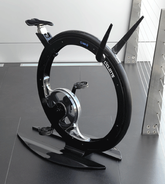
The Lamiflex Group developed an exercise bike called the Ciclotte. Its ultra-modern carbon fiber frame, touch screen display, and reduced pedal distance help ensure the correct bio-mechanics throughout the complete leg rotational movement. The large central wheel forms the cornerstone of the design and is reminiscent of the classic unicycles dating back to the end of the 1800s.

The Ciclotte is designed to accurately reproduce the dynamics and performance of on road pedaling and is deal for high intensity aerobic training such as spinning which is all possible because of the innovative epicycloid crank system. A dual satellite system which uses four gears with varying cogs in a functional space of only 58mm. By multiplying the number of flywheel rotations, about four flywheel rotations to every pedal rotation, it helps generate a high-intensity magnetic field (from the main wheel) which maximizes the resistance level and produces plenty of thigh-burning resistance.

A first aesthetic prototype was produced to test the market feedback before moving onto a fully functional prototype. To guarantee the exact requirements and size of all functional mechanical components, including the carbon-fiber handlebar and saddle, all components were designed in 3D and simulated as virtual assembly to highlight any potential issues prior to the assembling procedure where more than 60 separate components were finally brought together.

During this process, Lamiflex evaluated CAD/CAM software and migrated from a parametric-based system to Vero Software’s VISI product. The company is running multiple licenses of VISI Modeling, VISI Analysis for Design, and VISI Machining with Compass Technology for 2D through five-axis milling.

According to Federico Castelli, Lamiflex R&D director and Ciclotte project leader, “We used VISI for the design and manufacture of all composite parts that were used to build the Ciclotte. With regard to the molds for the carbon fiber wheel and the handlebar, all of this was achieved in less than 100 hours of CAD work.

Once the molds were complete and polished, the fabric and epoxy resin are applied and then inserted in to a vacuum bag and place inside the autoclave for the curing process. Once hardened, the parts are passed through to the CAM department for finish machining.

The company operates several milling machines including two simultaneous five-axis CNC’s running VISI Machining. For the finish machining of the composite products, the trimming method is often used where the side of the tool is driven along the surface edge. For additional control, synchronization curves can be used to control the tool movement in local areas where the potential direction changes are at their most extreme. For the machining of planar holes, the tool is tilted perpendicular to the surface, but when product holes are difficult to reach, and an extra tilting of the tool is required in order to avoid collision with the tool holder. When the toolpath is complete, the machine operator is able to virtually walk through the complete program using the kinematic simulator and prove the toolpath is collision-free. Today, the Ciclotte is available in full carbon, silver (fiberglass), and steel. The product was launched in the UK in September 2010.

Lamiflex
www.lamiflex.it

Vero Software
www.vero-software.com

Filed Under: 3D CAD Package Tips, Featured Tagged With: CAD/CAM, Ciclotte, CNC, Compass Technologies, Lamiflex, Vero Software, VISI

Guitar maker uses software for slick designs

January 29, 2011 By Laura Carrabine Leave a Comment

JEH Guitars is a one-man company in Denmark. Owner, Jens Hvidberg, has been designing and manufacturing custom instruments since 2000. Most of his guitars are unique individual pieces. A design and manufacturing process that is fast, easy to use, and responsive to the exacting demands of his customers is critical.

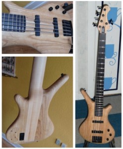
In the past, Hvidberg created many of the guitar bodies by hand while searching for an inexpensive set of CAD and CAM tools to make the process faster and more efficient. Rhino provided him with CAD software with all the capabilities of more expensive commercial applications. T-Splines and RhinoCAM software were the plug-ins he needed to support the art-to-part process.

A recent project included a redesign of a four-string bass into a five-string version with the body cut from a single piece of wood. Using T-Splines, Hvidberg could build a guitar body that could be easily modified. With reference pictures, he moved and changed control points on the T-Splines surface until he obtained the right shape. Final details were added with standard Rhino features.

Using RhinoCAM, it was easy to generate 3D tool paths for CNC machining. First he made the paths for the outline with the profiling feature and the paths for pocketing. Throughout the process, he kept the shape as regular as possible to maintain good fixture points. Actual machining was done with a 3D roughing operation and a finishing operation with a ball end mill. The final finish was created with sandpaper by hand.

Hvidberg said, “These tools make it possible for my customers to go from their own design ideas to the finished product without investing a lot of money. My templates are not hanging on the wall cut out in plywood but are in CAD files. They are easy to change and customize.

JEH Guitars

www.jens-h.dk

T-Splines

www.tsplines.com

Filed Under: 3D CAD Package Tips, Featured, Rhino Blogs Tagged With: cad, CNC, Rhino, RhinoCAM, T-Splines

CAM – Face classification

July 13, 2010 By Laura Carrabine Leave a Comment

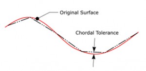
To explain the principle, if you simply break a 3D curve into equal length lines, the deviation of the lines from the curve would change as the curvature became larger and smaller. However, using a chordal deviation, the operator defines the maximum distance between the chord and the original geometry. The major benefit of using a chordal deviation to control the 3D mesh is that you have a consistent, predictable deviation.

You may then ask why not a set of very small chordal tolerance? In theory you can but this does effect the data size and also produces extra CNC code when it may not be necessary. You also have to be aware that on older machines without high speed controllers, the extra movements could choke the machine if the feed rates are not reduced. Dropping the feed rate is non-productive and reducing the accuracy means more time polishing and a less accurate part.

Okay, with the problem explained, the following tip shows how it is possible to improve this situation by defining a different set of chordal parameters based on face type.

When defining the piece parameters, the general chordal tolerance and angular tolerance is applied to the complete model. However, there is a face classification box that open an additional set of parameters that separates the tolerances for planar and radiused faces.

If the face classification box is NOT active, the general tolerances are applied to the complete model.

If the face classification box IS active, additional tolerance parameters become active. This allows the operator to separate the model into 3 tolerance bands – planar faces, radiused faces, and the general faces.

The major advantage of the mesh optimization is that it allows the operator to be more creative with the machining tolerances and still retain a sensible model size.

If you use the face classification option within the piece definition, it is then possible to graphically display and sort by face type when displaying the mesh within the piece manager. Even at this point within the tree structure, it is possible to select an individual face and define a different chordal and angular tolerance. If individual face parameters are applied, the face will be displayed with a different icon within the tree.

Vero Software
www.vero-software.com

Filed Under: 3D CAD Package Tips, CAD Hardware Tagged With: 3D, cam, chordal, CNC, Vero Software

Primary Sidebar

3D CAD NEWSLETTERS

MakePartsFast

Follow us on Twitter

Tweets by 3DCADWorld

Footer

3D CAD World logo

DESIGN WORLD NETWORK

Design World Online
The Robot Report
Coupling Tips
Motion Control Tips
Linear Motion Tips
Bearing Tips

3D CAD WORLD

  • Subscribe to our newsletter
  • Advertise with us
  • Contact us
Follow us on Twitter Add us on Facebook Add us on LinkedIn Add us on Instagram Add us on YouTube

3D CAD World - Copyright © 2021 · WTWH Media LLC and its licensors. All rights reserved.
The material on this site may not be reproduced, distributed, transmitted, cached or otherwise used, except with the prior written permission of WTWH Media.

Privacy Policy