• Skip to primary navigation
  • Skip to main content
  • Skip to primary sidebar
  • Skip to footer

3D CAD World

Over 50,000 3D CAD Tips & Tutorials. 3D CAD News by applications and CAD industry news.

  • 3D CAD Package Tips
    • Alibre
    • Autodesk
    • Catia
    • Creo
    • Inventor
    • Onshape
    • Pro/Engineer
    • Siemens PLM
    • SolidWorks
    • SpaceClaim
  • CAD Hardware
  • CAD Industry News
    • Company News
      • Autodesk News
      • Catia News & Events
      • PTC News
      • Siemens PLM & Events
      • SolidWorks News & Events
      • SpaceClaim News
    • Rapid Prototyping
    • Simulation Software
  • Prototype Parts
  • User Forums
    • MCAD Central
    • 3D CAD Forums
    • Engineering Exchange
  • CAD Resources
    • 3D CAD Models
  • Videos

Creo

Debating the Most Efficient Way to Go from Concept to Documentation

April 15, 2014 By Barb Schmitz Leave a Comment

The conceptual phase of design is the only one within the product development window that must be inherently fluid, and in a sense, should be done in a leisurely manner. What, you ask? The word “leisure” is probably not used often when it comes to designing products, right? OK, let me explain.

In order to fully evaluate a suitable number of potential design concepts, engineers and designers must have the luxury of time. After all, how can you determine an optimum solution until you’ve discounted an adequate number of bogus ones? Unfortunately, not many of them get that time.

According to a conceptual design study conducted by PTC, 92% of respondents felt that their product development process would benefit tremendously from the ability to evaluate more concept ideas before moving forward into detailed design and documentation. Another 61% said that the concept design process is often cut short to due schedule constraints.

Time, after all, is critical to meeting design production schedules and shipping products on time. It’s the underlying reality of all those involved with product development.

This concept design for Yamaha was created by a Alberto Agnari. It included concept boards, sketches and traditional and digital renderings.

Which route to take: direct or feature-based?

Once a concept design has been approved and moved forward, time is of the essence. During our “The Pros and Cons of 3D Modeling Paradigms” webinar, one of the questions posed to our panel of speakers was in regards to what modeling paradigm is best in terms of time efficiency when moving from the concept stage to the documentation state, keeping in mind that a good percentage of the dimensions can be automatically generated within the history-based model. The answers were surprising and I thought worth sharing.

Dan Staples, vice president, Solid Edge Product Development, Siemens PLM Software

In a history-based system the dimensions are in the sketches and then those are retrieved into the drawing. In a direct modeling system, or at least in Solid Edge, the dimensions take the form of what we call PMI (product manufacturing information) or the 3D dimensions that are on the faces of the model instead of in the sketches. That doesn’t change the ability to retreat those into the drawing. The fact is that they’re on the faces instead of the sketches, same thing in terms of ability to retrieve those that are in the drawing and use them.

Brian Thompson, vice president of Creo Product Management, PTC

Yeah, I think if you have good workflows for creating or showing those dimensions in the 2D context, it could be similar in terms of efficiency to do either. I don’t see one modeling paradigm strongly standing out. There’s good efficient workflows for creating dimensions on models that have no underlying sketches, and there’s good workflows for showing them on models that do. As Dan and I have said, dimensions in the direct modeling environment can, in fact, still drive geometry if the user tells the system that’s what he wants.

You can still even get that behavior. Maybe not to the level you would get with a large feature-based, history-based parametric model, but you could still get that behavior. There may be some circumstances where one is slightly better than the other, but I’d say it’s fairly close in terms of efficiency to create that documentation. Would you agree Dan?

Dan Staples

I would actually say it’s somewhat more efficient. One of the constraints we forget about is that when you build up a history-based model, you build it up sketch by sketch by sketch. That’s not necessarily a natural way to dimension the part. In fact, it’s pretty bad practice in terms of a dimensioning scheme because you tend to have a lot more dimensional stack ups than you would like. Whereas if you’re in a direct modeler, you can put in dimension between two faces on the model that are far from each and there’s 50 features in between, and so you can actually have a much more natural dimensioning scheme that’s more immediately usable in the drawing when you see direct models in my opinion.

Brian Thompson

Yeah, I think we’ll agree there that bad modeling technique and your history-based parametric modeling will make it even harder in the drawing to do that. If you got a good, well-done history tree then maybe it’s not as hard but it’s a good point.

The bottom line

Though it’s not easy to sum up all the good points here, its clear the most time-efficient way to move your designs from concept to documentation is to use best practices when it comes to how you model your products and good dimensioning workflows. In other words, the use of good modeling techniques will always get you from Point A to Point B faster, whether you’re working in a direct modeling or feature-based modeling 3D CAD system.

If you missed the “Pros and Cons of 3D Modeling Paradigms” webinar, you can watch it in its entirety here.

Barb Schmitz

Filed Under: 3D CAD Package Tips, Creo, Siemens PLM Tagged With: concept design, Creo, documentation, Solid Edge

The Challenges of Model Editing in the Multi-CAD World

February 27, 2014 By Barb Schmitz Leave a Comment

In today’s world, most engineers and designers are now accustomed to dealing with CAD data created in other CAD systems. With design collaboration with suppliers, partners, and customers being a key component of today’s product design, the use of multiple CAD systems has become the norm.

As a result, companies must become proficient at working with CAD data in multiple formats in order to succeed. Not only must they be able to send and receive data in multiple CAD formats, but also they must be able to quickly get to work on that CAD data without having to rebuild models from scratch or waste too much time fixing data to get clean geometry.

On average, companies use 2.7 different CAD systems internally. Here’s another daunting statistic: nearly half (49%) of companies struggle with importing models created in other CAD tools into their 3D CAD system, and another 59% say modifying imported models from other CAD tools is difficult using their CAD software.

Vital design cycle time is wasted when models must be recreated; yet making changes to those models is also problematic as intelligent features and patterns built in by feature-based CAD authoring systems are often lost once imported into another CAD system. So what is a company to do when navigating through multi-CAD environments?

Nearly half of all product development companies continue to struggle with how best deal with CAD data originating in other CAD systems. Image courtesy of Siemens PLM.

During the Q&A portion of a recent webinar, “The Pros and Cons of 3D Modeling Paradigms,” a question was posed to the speakers as to how best to approach making changes to CAD models that were created in a different CAD system. I think the responses are worth sharing as it’s something with which half of all companies continue to struggle.

Brian Thompson, vice president of Creo Product Management at PTC
“It’s pretty obvious that data inoperability between CAD systems has been tried at the feature level, and it’s generally not all that successful, at least not in a robust way. In general, when you take data in from another CAD system, you’re going to get information like assembly structure but for the geometry, you’re going to get just a closed volume, assuming that the data translation for the solid or the geometry came across well. Unless you want to just use your own history-based features to cut geometry out and recreate it from scratch, direct modeling tools are an ideal set of tools to manipulate geometry that’s come in from a CAD system in which you don’t have the features any longer.

It’s a pretty nice approach to be able to move faces, to align faces, to resize analytic geometry, to symmetrically change a model if it looks like it might be symmetric. There’s lots of tools built into most direct modeling environments that will give you great control over geometry regardless of the fact that that geometry had no features when it came over. You can actually use direct modeling tools to really control that geometry in pretty sophisticated ways despite the fact that when you got it, you didn’t get any features at all.”

Dan Staples, vice president of Solid Edge Product Development, Siemens PLM.

“I would just add that I don’t think it is, to be honest, any contest. If you were to be reading data from another system and you could choose to read it into the history-based environment and non-history-based environment, definitely read it into the non-history-based environment. You have much more flexibility and ability to make the changes you want to make.

I would suggest that in fact if you’re a diehard history-based user, but your system supports a non-history sort of mode, that this is where you want to try it. Certainly we’ve seen our users who when they want to get started with, in our case, synchronous technology and they are asking themselves ‘do I want to use it or do I not want to use it?’ Well, by gosh, the first place to use it (direct modeling) is with that imported data, it’s definitely a homerun there.”

Chad Jackson, principal analyst at Lifecycle Insights and a speaker at the webinar, authored a whitepaper that addresses the challenges of working in multi-CAD environments. You can read “Multi-CAD Data, Unified Design” here. To listen to the entire “The Pros and Cons of 3D Modeling Paradigms” webinar, click on this link.

Barb Schmitz

Filed Under: Creo, News, Siemens PLM Tagged With: cad, Creo, PTC, Solid Edge

The failed promise of parametric CAD part 5: A resilient modeling strategy

June 25, 2013 By Evan Yares 3 Comments

bamboo-garden
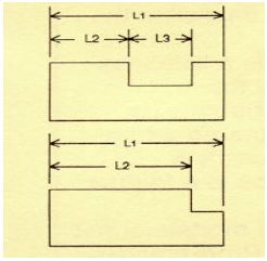
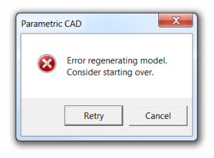
The model brittleness problem inherent with parametric feature-based modeling is a really big deal. And it’s something, honestly, that I don’t have a great answer for. I’ve even asked a few power users who I know, and their answers seemed to involve a bit of hand-waving, and a reference to having lots of experience.

While best practices are a potentially good step forward, they need to be straightforward enough that mere mortals (as opposed to power users) can follow them.

Around Christmas last year, I got a call from Richard Gebhard, an engineer’s engineer, who has made his living selling CAD, and training people to use it (including more than his fair share of power users), for longer than he would like me to admit. (I’m pretty sure I’ve been in the CAD industry longer than him, though.) Richard told me he had something he wanted to show me, and if I’d take the time to meet him, he’d buy me lunch.

What Richard showed me was a way of creating and structuring CAD models that made a lot of sense. It not only reduced parent-child dependencies, but it made them more predictable. And, more importantly, it made it a lot easier for a mere mortals to scan through the feature tree, and see if there were any grues (it’s a technical term. Feel free to look it up.)

Over the next several months, we had lunch several times. I made suggestions. He rejected some, accepted some, and thought about others. At the same time, he was bouncing his ideas off several of his best power users (including his son). By a couple of months ago, he had refined his system to the place where it would work impressively well with nearly any parametric feature-based CAD system. So, he went to work finalizing his presentation.

I had mentioned that Delphi, by patenting some of the elements of horizontal modeling, limited the number of people who could benefit from it. (Worse for them, they patented it, then filed bankruptcy. That didn’t help much.) Richard’s goal wasn’t to monetize his process. His goal was to evangelize it. To help CAD users—both power users and mere mortals—to get their jobs done better.

Richard and I had talked, over time, about what he should call this process. At first, I liked the word “robust.” In computer science, it is the ability of a system to cope with errors during execution. In economics, it is the ability of a model to remain valid under different assumptions, parameters and initial conditions. Those are good connotations. But, then I thought of one of my favorite examples of robustness. The first time I visited Russia, I noticed that the apartment buildings were built of thick poured concrete. Very robust. And nearly impossible to remodel.

Richard’s system wasn’t robust. It was resilient. So, he has named it the Resilient Modeling Strategy. RMS.

So far, I’ve written over 2,600 words, to provide some background on the problems of parametric modeling, and some of the solutions that have been offered over the years. But, after all that, I’m not going to tell you anything more about RMS. At least, not yet.

Tomorrow, Wednesday, June 26, Richard will present RMS for the first time ever, at Solid Edge University, in Cincinnati, Ohio. His presentation will start at 9:00AM local time, and will be in room 6 of the convention center. If you’re there, put it on your calendar. If not, you’ll need to wait until Richard gets back to Phoenix, and I publish a follow-up post.

RMS is not anything difficult, or fundamentally new. It’s just an elegant distillation of best practices, designed to work with nearly any parametric CAD system, and simple enough that it doesn’t get in the way.  It’ll help you make better CAD models faster.

Filed Under: Alibre, Autodesk, Creo, Design World, Evan Yares, Featured, Inventor, Pro/Engineer, Siemens PLM, SolidWorks Tagged With: Creo, Inventor, IronCAD, Solid Edge, SolidWorks

The failed promise of parametric CAD part 4: Going horizontal

June 25, 2013 By Evan Yares 12 Comments

In the early 90s, Ron Andrews, a senior product designer at Dephi’s Saginaw Steering Systems Division, became fed-up with the difficulties of editing parametric CAD models. So, he and a team of his colleagues, including Pravin Khurana, Kevin Marseilles, and Diane Landers, took on a challenge of trying to find a solution.

They came up with an interesting concept that they called horizontal modeling. Here’s a description of it from their patent abstract:

“Disclosed is a horizontal structure method of CAD/CAM manufacturing where a base feature is provided and one or more form features added to it to form a model. The form features are added in an associative relationship with the base feature, preferable a parent child relationship, but are added in a way as to have substantially no associative relationships with each other. The result is a horizontally-structured Master Process Model where any one form feature can be altered or deleted without affecting the rest of the model. Extracts are then made of the Master Process Model to show the construction of the model feature by feature over time. These extracts are then used to generate manufacturing instructions that are used to machine a real-world part from a blank shaped like the base feature.”

Here’s a picture that makes it clearer:

Horizontal Modeling

The simplest explanation I can give for it is this: You create a base feature, and bunch of datum (working) planes. You attach all the child features to those datum planes. Viola: no parent-child problems.

I admit that I’m not going to do justice to horizontal modeling in this conversation. There’s actually quite a bit to it, and it makes a lot of sense when coupled with computer-aided process planning (CAPP.)

Horizontal modeling has a handful of problems. First, it does a pretty good job of killing the possibility of having design intent expressed in the feature tree. Next, it works better with some CAD systems than others. (When horizontal modeling was in the news, SolidWorks had a problem managing the normals on datum planes, so it didn’t work too well.) The deadliest problem is that Delphi got a bunch of patents on the process, then licensed it to some training companies. From what I can see (and I may be wrong), none of these training centers offer horizontal modeling classes any more.

While, technically, you can’t use horizontal modeling without a patent license from Delphi, the concepts at its core are fairly similar to things that CAD users have been doing for years. A few years ago, Josh Mings posted on a couple of online forums that “Horizontal Modeling is just one word for it, you may also know it as Skeleton Modeling, Tier modeling, Sketch Assembly modeling, CAD
Neutral Modeling, or Body Modeling.” (It’s actually two words for it, but I get his point.)

Horizontal modeling is not a silver bullet solution for the problems inherent in parametric feature-based CAD. It’s just a best practice—a strategy for getting around the problems. It seems to be headed in the right direction, but it suffers from the complexity that comes from trying to fix too many problems at once.

Next: A Resilient Modeling Strategy

Filed Under: Alibre, Autodesk, Creo, Design World, Evan Yares, Featured, Inventor, Pro/Engineer, Siemens PLM, SolidWorks Tagged With: Creo, Inventor, IronCAD, Solid Edge, SolidWorks

The failed promise of parametric CAD part 3: The direct solution

June 25, 2013 By Evan Yares 5 Comments

Pull-PushDirect modeling—a syncretic melding of concepts pioneered by CoCreate, Trispectives, Kubotek (and many others)–has shown the most promise to cure the parametric curse.

Direct modeling is today’s hot CAD technology. PTC, Autodesk, Siemens PLM, Dassault (CATIA, but not so much SolidWorks), IronCAD, Kubotek, Bricsys, SpaceClaim (and certainly some other companies I’ve forgotten) all have their own unique implementations of it.

The common thread in direct modeling is to use standard construction techniques when modeling, and feature inferencing (or recognition) when editing. It’s easier said than done. It’s taken about 35 years of industry research to get to the place we are today—where you can click on a face of a model, and the system will recognize that you’re pointing to a feature that has some semantic value. And that’s not even considering the tremendous amount of work that has been required by legions of PhD mathematicians to develop the math that lets you push or pull on a model face, and have the system actually edit the geometry it in a useful manner.

For the CAD software, figuring out which way to edit a selection is almost a mind reading trick: A user clicks and drags on a part of a model. What would they like to happen? In some cases it’s easy: Drag once face of a rectangular block, and the system will just make it longer or shorter. But if the block is full of holes, bosses, and blends, it becomes a lot more complicated. What should the system do if you drag a face so far back that it consumes another feature, and then pull it back to where it was? Should the consumed feature be lost forever, or should the system remember it in some way, so it can be restored?

There are no right answers. It seems that no two direct modeling systems handle the decision of what is a “sensible” edit in the same way.

While direct modeling absolutely solves the model brittleness problem inherent with parametrics, it does it by simply not using parametrics. Even with hybrid parametric/direct CAD systems, the answer to the parametric curse is still to not use parametrics when you don’t need to.

The solution of “use direct modeling when you can, and learn to live with parametric hassles when you can’t” just isn’t very satisfying to me.

Next: Going horizontal

Filed Under: Alibre, Autodesk, Creo, Design World, Evan Yares, Featured, Inventor, Pro/Engineer, Siemens PLM, SolidWorks Tagged With: Creo, Inventor, IronCAD, Solid Edge, SolidWorks

The failed promise of parametric CAD part 2: The problem is editing

June 25, 2013 By Evan Yares 4 Comments

ErasermIn the previous post, I wrote about the failed promise of parametric CAD: problems such as parent-child dependencies and unwanted feature interactions, coupled with no easy way to either prevent, or check for them.

The difference between modeling and editing in a parametric CAD system is simply the difference between creating things from scratch, and modifying things you’ve already created. The distinction may seem academic, but it is only when editing that parent-child dependencies are a potential problem.

Consider a scenario, of creating a parametric part—one that you’ve worked out in your head pretty well ahead of time—where you start from scratch, modeling sequentially, and spending all your time working on the most recent feature without needing to go back to edit upstream features.

In that context, the model’s parent-child dependencies would exist, but would be benign. They’d never get in your way. That is, until you went back to edit the part.

In most cases, people don’t build models from scratch without periodically going back to adjust earlier features from time to time. In that process, they’ll catch, and be able to deal with, some of the dependencies. But not likely all, or even most, of them.

I’ve heard experienced CAD people use an interesting term for models with hidden and untested parent-child dependencies: Parts from hell. When you’re trying to modify them, you never know when a small change might cause them to completely fall apart. I think a better, more descriptive, term is brittle: Hard, but liable to break or shatter easily.

This also suggests a descriptive term for CAD models which are not liable to break or shatter easily: resilient.

I’ve only ever seen one group of users who could consistently create complex yet resilient parametric parts models from scratch: PTC application engineers from the early to mid-1990s. Of course, they could only do it during customer benchmarks, with parts they’d practiced ahead of time, where they had worked-out and memorized all the steps, and where they had a good idea of the parameter ranges. Even then, if you were to ask them to change a dimension that would cause a topological change, the models might unceremoniously blow up.

Not to paint too bleak a picture, there are certainly CAD power users who have the skills to create resilient CAD models. I’ve met more than a few of them: true professionals, who by combining experience, insight, and education, have earned the respect of their peers. They understand how to structure CAD models to avoid any problems with brittleness.

Nah. I’m just messing with you. Power users struggle with this just like us mere mortals. It’s just that their models don’t usually fall apart until you go outside the scope of parametric changes they had anticipated. Give power user’s carefully crafted CAD model to a user who has a black thumb (I’m sure someone comes to mind), and they’ll find ways to blow it up that the power user never imagined.

Next: The direct solution

Filed Under: Autodesk, Creo, Design World, Evan Yares, Featured, Inventor, Pro/Engineer, Siemens PLM, SolidWorks Tagged With: Creo, Inventor, IronCAD, Solid Edge, SolidWorks

The failed promise of parametric CAD part 1: From the beginning

June 25, 2013 By Evan Yares 28 Comments

The modern era of 3D CAD was born in September 1987, when Deere & Company bought the first two seats of Pro/Engineer, from the still new Parametric Technology Corporation. A couple of years later, Deere’s Jack Wiley was quoted in the Anderson Report, saying:

“Pro/ENGINEER is the best example I have seen to date of how solid modelers ought to work. The strength of the product is its mechanical features coupled with dimensional adjustability. The benefit of this combination is a much friendlier user interface plus an intelligent geometric database.”

According to Sam Geisberg, the founder of PTC:

“The goal is to create a system that would be flexible enough to encourage the engineer to easily consider a variety of designs. And the cost of making design changes ought to be as close to zero as possible. In addition, the traditional CAD/CAM software of the time unrealistically restricted low-cost changes to only the very front end of the design-engineering process.”

To say Pro/E was a success would be a terrible understatement. Within a few years PTC was winning major accounts from the old-line competitors. In 1992, on the strength of its product, PTC walked away with a 2,000 seat order from Caterpillar that Unigraphics had thought was in the bag.

The secret to Pro/E’s success was its parametric feature-based solid modeling approach to building 3D models. To companies such as Deere and Caterpillar, it offered a compelling vision. Imagine being able to build a virtual CAD model of an engine, and, by changing a few parameters, being able to alter its displacement, or even its number of cylinders. And even if that wasn’t achievable, it would be a great leap forward to just be able to rapidly create and explore design alternatives for parts and assemblies.

Yet, things were not that easy. In 1990, Steve Wolfe, one of the CAD industry’s most insightful observers, pointed out that Pro/E was incapable of making some seemingly simple parametric changes.

Pro/Engineer placed limits on the range of parameters. (A designer could not increase the dimension of L2 to point that L3 vanished.)

David Weisberg, editor of the Engineering Automation Report (and from whose book, The Engineering Design Revolution, I have liberally cribbed for this article), pointed out the fundamental problem with parametrics:

“The problem with a pure parametric design technique that is based upon regenerating the model from its history tree is that, as geometry is added, it is dependent upon geometry created earlier. This methodology has been described as a parent/child relationship, except that it can be many levels deep. If a parent level element is deleted or changed in certain ways it can have unexpected effects on child-level elements. In extreme cases (and sometimes in cases that were not particularly that extreme), the user was forced to totally recreate the model… Some people described designing with Pro/ENGINEER to be more similar to programming than to conventional engineering design.”

Weisberg barely scratches the surface of the issues that can create problems.

In 1991, Dr. Jami Shah wrote an Assessment of Features Technology, for Computer-Aided Design, a journal targeted to people doing research in the field of CAD. He identified that there were problems with features:

“There are no universally applicable methods for checking the validity of features. It is up to the person defining a feature to specify what is valid or invalid for a given feature. Typical checks that need to be done are: compatibility of parent/dependent features, limits on dimension, and inadvertent interference with other features. In a study for CAM-I, Shah et al. enumerated the following types of feature interactions:

  • interaction that makes a feature nonfunctional,
  • non-generic feature(s) obtained from two or more generic ones,
  • feature parameters rendered obsolete,
  • nonstandard topology,
  • feature deleted by subtraction of larger feature,
  • feature deleted by addition of larger feature.
  • open feature becomes closed,
  • inadvertent interactions from modifications.”

The important thing to notice here is that, not only are there multiple failure modes for features, there are also no universal methods for validating features. It’s left up to the user to figure out. And that process, as Weisberg hinted, is much too difficult.

Rebuild Error

Since the early days of Pro/E, a lot of work has been done, both by PTC and other companies in the CAD industry, to improve the reliability and usability of parametric feature-based CAD software. Yet, the problems that Weisberg and Shah identified still exist, and still get in the way of users being able to get the most from their software.

Next: The problem is editing.


Filed Under: 3D CAD Package Tips, Autodesk, Creo, Design World, Evan Yares, Featured, Inventor, Pro/Engineer, Siemens PLM, SolidWorks Tagged With: Creo, Inventor, IronCAD, Solid Edge, SolidWorks

How would you design an electric motorcycle?

March 26, 2013 By Evan Yares 1 Comment

I often find myself looking at manufactured products, and wondering “how would you go about designing something like that?”

For some things, the sheer scale of the problem is so large that it’s hard to wrap your head around it.  But, there are many things that are more human scale, in complexity and difficulty. A good example is an electric motorcycle.

Some time back, I was having a conversation with some folks from  a company that does crowd-sourced engineering projects, about ideas for interesting projects. I suggested an electric motorcycle.  My thinking was that, with the availability of standard motors, control electronics, battery packs, and lots of OEM parts (forks, wheels, brakes, and even frames), it would be an interesting exercise, with relatively simple engineering, and an emphasis on industrial design.

I was reminded of this conversation when I learned I’d be hosting a webinar with industrial designer and engineer, Nout Van Heumen. Nout has become somewhat of a rock star in the Dutch industrial design scene. While his regular job is pretty much standard engineering work, his side job is a lot more fun: doing industrial design of some very cool projects. One project of particular note is the Orphiro electric motorcycle.

orphiro5

Nout will be talking about his approach to designing the Orphiro during our webinar this morning, at 8AM PST (11AM EST). You can register for it at http://www.designworldonline.com/webinar-how-to-deliver-real-time-concept-design-with-ptc-creo-2-0/

UPDATE: We just finished the webinar.  Here are a few of my takeaways:

Here are some  of my take-aways:

  • Think, from the beginning, in terms of what the manufacturer needs to make the part. In the examples Nout showed, his deliverable included both the parts and the molds to make them.
  • Don’t be afraid to start over, if the structure of your model isn’t working out right.
  • You don’t need to be a CAD genius to do impressive work, but you do need to master your tools.
  • Creo 2.0 seems at home modeling beautiful aesthetic parts.

We recorded the webinar, and after it is edited, it will be available for replay, at the link shown above.


Filed Under: Creo, Evan Yares, Featured Tagged With: Creo, Industrial Design, PTC

Rock and Roll industrial design

March 25, 2013 By Evan Yares Leave a Comment

I’m always interested in how people use CAD software to do interesting projects.

Nout Van Heumen is an industrial designer and engineer whose day job, so to speak, is in the packaging and insulation business. But Hout has developed a name for himself by taking on some really interesting freelance jobs.

One of his projects that I particularly like is the Aristedes OIO guitar. If you check out the picture of this guitar, you can see that it’s pretty cool looking. It’s also pretty innovative.

aristides-OIO-redmetallic-20133m

Tuesday morning, from 11:00 to 11:30 AM, Eastern time, I’ll be hosting a webinar with Nout, where he talks about his approach. Though PTC is sponsoring this webinar, it’s not going to a big sales pitch. It’s going to be a person talking about how he designs cool stuff.

My sense is that this webinar is going to be really interesting for anyone who is interested in conceptual design. Even people who don’t use Creo (which happens to be Nout’s tool of choice.)

So, please join Nout and myself tomorrow. You can register for the webinar here:

http://www.designworldonline.com/webinar-how-to-deliver-real-time-concept-design-with-ptc-creo-2-0/

o1o-mould


UPDATE:  Webinar is over.  Nout showed the new Aristedes 020 guitar, as well as the mold used to make it.  Interesting how he planned out the mold parting line, right from the beginning.

We will have a recording of the webinar available for replay, as soon as it is edited.

Filed Under: Creo, Evan Yares, Featured Tagged With: Creo, PTC

Cheetah, Creo, and 2D geometric constraint solvers

June 23, 2012 By Evan Yares 10 Comments

Last week, I wrote, in Solving the CAD concurrency problem, about 2D geometric constraint solvers.

Solvers are one of the major components used in 3D CAD programs, and are the main part of the sketcher used in parametric feature (history based) modelers. They’re also used behind the scenes in direct modeling CAD systems. They’re pretty important, and have a significant effect on a CAD program’s performance.

Cloud Invent, a small software developer, made up—so far as I can tell—mostly of PhD mathematicians, recently posted a couple of interesting videos on YouTube. The first video showed the performance of the sketcher in PTC Creo Parametric 1.0, when dealing with massively large sketches.

The next video they posted was of their “Cheetah” solver, running on an identical sketch.

If you take the time to watch these two videos, you’ll see a couple of important things. First, the Creo Parametric solver seems to fall apart (become unstable) once faced with a large sketch. And the Cheetah solver doesn’t.

I chatted (by email) last week with both the folks from Cloud Invent, and from PTC, to try and understand what I was really seeing. I also duplicated the demo from the videos using Autodesk Inventor, which uses Siemens PLM’s 2D DCM constraint manager.

Lev Kantorovich, from Cloud Invent, responded to my questions.

Q: What are you doing differently in Cheetah that what’s being done with other 2D constraint solvers?

A: The main advantage of our solver is that it has O(n) memory and time requirements (to compare, solver of PTC requires O(n2) amount of memory and O(n3) arithmetic operations to solve a system of constraint equations. The situation is similar with other solvers).

Modern solvers (that of PTC) use general purpose methods of linear algebra. But the system of linear equations that appears in CAD is not “general purpose” – the matrix of such a system is very sparse. We know in advance that each row of this matrix has a fixed number of non-zeros (let’s say, not more than twenty non-zeros). If you can use this information efficiently, you will dramatically improve performance and decrease memory requirements of the solver.

That is exactly what we managed to do in our Cheetah solver. I do apologize that I can’t provide you the detailed information about our algorithm (there is a remarkable mathematic work behind this and five or six PhD dissertations in some of the leading USA universities – in the end of the nineties this issue was in focus of the researchers), but I want to mention one additional advantage of the approach – our methods are well suited for parallel processing.

Q: Are you supporting 3D constraints?

A: So far we tested our solver in 2D sketcher only, but I don’t see any reasons why it shouldn’t work for 3D constraints as well. Actually, this is the most interesting direction.

Traditional parametric CAD lives only in 2D sections – this is part of “parametric feature-based approach” to solid modeling. The reason for this is quite simple – these solvers can resolve only small models. That’s why complicated solid model is divided into hierarchic list of simple features (each one having its own parametric sketch) – known as “history tree”.

But we have a solver that is powerful enough to constrain the whole 3D model (using all reasonable 3D constraints). Now we can try to go away from the feature based approach with its notorious history tree and to unify in one 3D workspace parametric and direct modeling approaches. This is, actually, our main target.

Q: On your website, you say other solvers solve equations in the wrong manner, “using archaic numeric methods” (e.g., Newton iteration, Gauss eliminations and Gram-Schmidt orthogonalization.) That hints that you might be using symbolic methods—or perhaps a hybrid numeric-symbolic method?

A: No, we don’t use symbolic methods.

Our method may be described as:

By using the specifics of the system of linear equations (very sparse matrix), we subdivide the set of all equations into small groups and solve these small subsystems corresponding to these groups. Each subsystem has fixed requirements for memory and computation. The tricky part is how to choose these groups and how to coordinate data exchange between them – we use the iterative approach for that.

Q: You say that you have O(n) memory and computational efficiency. That accounts for number of geometric elements (n), but what about number of constraints (m)?

A: In Cheetah the number of arithmetic operations that is required to resolve system of equations is O(m), i.e., proportional to the number of constraints. It means that if you have millions of geometric entities, but few constraints, the system will be resolved fast.

Q: I’m not clear if you’re solving linear or non-linear equations.

A: We solve non-linear equations, but we do it in the standard way – by linearization on each step of non-linear iterations. Normally, there are very few non-linear steps (two, three, rarely more). Our “know how” is in solving corresponding linear equations.

Q: Can you give me more detail on your support for parallelism?

A: The parallelism is based on what was written above about our method – each small group of equations can be processed independently. The author of this method, Nick Sidorenko, thinks that what we doing is quite new.

Q: You don’t mention anywhere what type of objects you support (e.g. points, lines, circles, arcs, ellipses, planes, cylinders, spheres, NURBS, parametric curves, surfaces), or what type of constraints you support (e.g. coincidence, parallelism, tangency, curvature, etc.)

A: At this moment we have only the prototype. We were focused on proving concept of the algorithm (solving system of the sparse linear equations). We tested it with the 2D sketcher; we haven’t tested yet 3D objects (planes, cylinders, spheres, NURBS, parametric curves, surfaces).

Q: Do you have a Cheetah solver prototype available yet?

A: The prototype will be available soon for download from our site. It works at the moment with line segments and circles only. The set of constraints is also restricted – horizontal, vertical, same point, equal, parallel, perpendicular, tangent (between line and circle). It is also possible to set length of a line segment, distance between two points, radius of a circle, angle between two lines.

Once again, our goal was not a full range parametric sketcher. We used FreeCAD as a test platform for the algorithm. Perhaps, in the nearest future we’ll add more geometric entities (at least, circle arcs, and, may be, ellipses) and more geometric constraints.

Since Cloud Invent was using Creo Parametric as an example of a typical 2D solver, I wanted to get a response from PTC. Brian Thompson answered my questions.

Q: Do your customers seem generally satisfied with the interactive performance of the sketcher?

A: Yes, except when importing some large cosmetic sketches – i.e., something that users don’t want to reference in another feature. For this use case, our cosmetic sketch can be unconstrained, allowing much larger sketches to be imported without solver involvement.

Q: Does the sketcher’s performance have a significant effect on the overall regeneration time for 3D parametric models?

A: No, because highly complex relationships are generally not captured in sketches. They are generally captured at a higher level.

Q: Has your solver fundamentally changed in its underlying design from the early days of Pro/E?

A: Very tough question depending upon how you define “fundamentally”, but yes. Consider that early sketches had to be regenerated, while now we have a constraint-based solver. Then, consider that this constraint-based solver has had significant performance enhancements since its inception.

Q: Do you anticipate any significant improvements in the future, such as using some of the more modern developments for parallel solutions of systems of linear equations?

A: 2D is an area that we will continue to invest – improvements in 2D user experience and performance will be on the table for many releases to come as our 2D strategy on the Creo platform grows and matures.

Julie Blake, of PTC, also responded, when I pointed out the Cloud Invent videos to her:

As you could tell I’m sure, the video is a very academic example, not something used in production. However, the sketching environment overall is something that is important to PTC and is of course fundamental to geometry creation in any CAD application. The Creo team has continuously worked to improve the sketcher performance over the past several years and our general 2D capabilities – regardless of which app they are in – are expected to be a continued area of focus for us over many releases to come.

Julie was right. The Cheetah solver is not a commercial product yet. Though I suspect they have the first 90% of the work done on it, that just means they need to finish the other 90%. (That’s a software developer’s joke.)

As I looked carefully at the Cloud Invent video that showed Creo’s performance, what I saw, reading between the lines, was not instability in the Creo 2D solver. Rather it was a performance issue. With a very large sketch, the interactive performance of Creo got sluggish. If you just move and click your mouse when the system is responding slowly, you’re going to get unpredictable results. This is true with Creo, or with any interactive computer program.

I can’t say that I’m completely pleased with Creo’s ability to handle really large sketches. Yet, I’m not the one using the program. If Creo users are generally happy with its performance in this realm, then it’s good enough by my book. Creo’s support for unconstrained cosmetic sketches provides a reasonable solution for very large sketches. (If you’re a Creo user, and have any thoughts on this, please add a comment below.)

I find what Cloud Invent is doing to be quite interesting, and I’m hopeful that they’ll be able to get their product to point where it’s commercially viable. I suspect, though, that their best path to market may through working with (or being acquired by) a major CAD or components company. Preferably one with a whole bunch of users who’ll benefit from having access to Cloud Invent’s technology.

Filed Under: Creo, Evan Yares, Featured, News Tagged With: 2D DCM, Autodesk, Cloud-Invent, Creo, D-Cubed, Inventor, PTC, Siemens PLM, Sketcher, Solver

  • Go to page 1
  • Go to page 2
  • Go to page 3
  • Go to Next Page »

Primary Sidebar

3D CAD NEWSLETTERS

MakePartsFast

Follow us on Twitter

Tweets by 3DCADWorld

Footer

3D CAD World logo

DESIGN WORLD NETWORK

Design World Online
The Robot Report
Coupling Tips
Motion Control Tips
Linear Motion Tips
Bearing Tips

3D CAD WORLD

  • Subscribe to our newsletter
  • Advertise with us
  • Contact us
Follow us on Twitter Add us on Facebook Add us on LinkedIn Add us on Instagram Add us on YouTube

3D CAD World - Copyright © 2021 · WTWH Media LLC and its licensors. All rights reserved.
The material on this site may not be reproduced, distributed, transmitted, cached or otherwise used, except with the prior written permission of WTWH Media.

Privacy Policy