• Skip to primary navigation
  • Skip to main content
  • Skip to primary sidebar
  • Skip to footer

3D CAD World

Over 50,000 3D CAD Tips & Tutorials. 3D CAD News by applications and CAD industry news.

  • 3D CAD Package Tips
    • Alibre
    • Autodesk
    • Catia
    • Creo
    • Inventor
    • Onshape
    • Pro/Engineer
    • Siemens PLM
    • SolidWorks
    • SpaceClaim
  • CAD Hardware
  • CAD Industry News
    • Company News
      • Autodesk News
      • Catia News & Events
      • PTC News
      • Siemens PLM & Events
      • SolidWorks News & Events
      • SpaceClaim News
    • Rapid Prototyping
    • Simulation Software
  • Prototype Parts
  • User Forums
    • MCAD Central
    • 3D CAD Forums
    • Engineering Exchange
  • CAD Resources
    • 3D CAD Models
  • Videos

Evan Yares

The failed promise of parametric CAD, final chapter: A viable solution

November 18, 2013 By Evan Yares 5 Comments

Model reuseWhat is the failed promise of parametric CAD? In short, model reuse.

It’s a lot more difficult than it ought to be, for a variety of reasons. Several months back, I wrote a series of articles discussing those reasons, as well as some of the solutions that have come up over the years.  What was missing from the series was a final chapter; a detailed description of what could prove to be a viable solution to problems with model reuse: the resilient modeling strategy.

The resilient modeling strategy (RMS) is the brainchild of Richard “Dick” Gebhard. I wrote about Dick last June, in the article A Resilient Modeling Strategy. He’s a low-key guy with deep experience and serious expertise in the practical use of MCAD software. Over his career in CAD, he’s been a reseller for CADKEY, Pro/E, and most recently, Solid Edge.

RMS is a best practice for creating CAD models that are stable and easily reusable (even by inexperienced users.)  It can be learned and easily used by typical CAD users, it preserves design intent in models, and provides a mechanism by which managers or checkers can quickly validate a model’s quality.

Resilient Modeling Strategy

When Dick first started thinking about the concepts that make up the resilient modeling strategy, it was natural that it was in the context of showing the advantages of Synchronous Technology (The Siemens PLM brand name for its version of direct modeling.) In our discussions about RMS over the last year or so, I pointed out that, while I thought that RMS did indeed demonstrate the benefits of hybrid history/direct modeling in Solid Edge, for it to be taken seriously, and not be unfairly dismissed as a marketing initiative for Solid Edge, it needed to work with a wide variety of MCAD tools. I think Dick got where I was coming from, because he’s continued to refine and generalize RMS, with feedback from users of a number of MCAD systems.

In its current incarnation, RMS works particularly well with Solid Edge, as might be expected, but also works very well with Creo, NX, CATIA, and IronCAD (all of which are hybrid history/direct systems.) Further, with a few modifications, it can provide compelling value with SolidWorks, Inventor, and Pro/E (all of which are primarily history-oriented systems.)

It’s significant that RMS is also free to use. While Dick is available to provide presentations, seminars, and training, he has not attempted to patent, or keep as trade secrets, the underlying concepts of RMS. (He does claim a trademark on the term “Resilient Modeling Strategy,” which means that organizations offering commercial training on RMS will need to get Dick’s OK to use the term.)

Dick has posted an introductory presentation on RMS at resilientmodeling.com. While the entire presentation is 20 minutes long, the first 3-1/2 minutes cover the problems that people invariably experience when reusing or editing history-based CAD models. Watching that much will likely convince you to watch the rest.

On Wednesday, November 20, at 10:00 AM PST, Dick will be hosting a webinar on RMS. It’s scheduled to last just 30 minutes, with the emphasis on content, not hype. If you’re a serious CAD user or a CAD manager (or, for that matter, you work for an MCAD developer), it’ll be well worth your time to attend.

TL;DR: Resilient Modeling Strategy is a best practice for creating high quality reusable 3D MCAD models. It works with many CAD systems, it’s easy to learn and use, and it’s free. Big payoff for MCAD users. 

Presentation at resilientmodeling.com

Register for Nov 20 webinar on Resilient Modeling


Filed Under: Catia, Creo, Evan Yares, Featured, Inventor, News, Pro/Engineer, Siemens PLM, SolidWorks Tagged With: 3D CAD, Catia, Dassault Systemes, Evan Yares, Inventor, IronCAD, PTC, Siemens PLM, Solid Edge, SolidWorks

Autodesk Inventor ETO gets webified

March 20, 2012 By Evan Yares Leave a Comment

Autodesk has just introduced a new release of Autodesk Inventor Engineer-to-order (ETO) software that can be deployed over the web.

The new browser-based access is powered by the Autodesk Inventor Engineer-to-Order Server, which includes the ETO (Intent) Rules Engine and the Inventor Server (for model and drawing generation), as well as web services and server farm management software. Graphic display is via the Autodesk DWF format, for browsers with the Autodesk’s DWF Viewer browser add-on, and via raster graphics otherwise.

The Inventor ETO Server is licensed on a per-server basis, supporting 10 concurrent users. The included server farm management software supports load balancing and scaling. Because the server framework is session-based (i.e., not stateless), system requirements are about the same as for Autodesk Inventor. With big and complex models, you’re going to need to have pretty stout servers.

Autodesk is not currently offering Inventor ETO Server with software-as-a-service (SaaS) licensing, though, from a technical perspective, there doesn’t seem to be anything to prevent this. The software can be run in a virtual machine (VM), and hosted on a cloud service. The applications at http://etosamples.autodesk.com, for example, are running on Amazon EC2 instances.

Applications to be deployed on the Inventor ETO Server are created with the Inventor ETO Series product, using a Visual Studio-based development environment, supporting the Intent language and .NET languages like VB.NET and C#.

While the Intent language has evolved and been modernized for .NET compatibility, and based on feedback from users, its heritage traces back to the mid-1980s, to ICAD, one of the pioneering products in Knowledge Based Engineering (KBE.)

The Intent Rules Engine used by the Inventor ETO Server is powerful enough to implement nearly any sort of engineer-to-order application you could envision. It can be used to capture geometric and configuration knowledge, as well as business rules. Because the Intent Rules Engine provides the capability to create dependencies between designs (objects), it effectively allows the creation of workflows.

Out of the box, Inventor ETO Server has no ready-made integrations with enterprise systems, such as ERP, SCM, CRM, PDM, or even, for that matter, Autodesk’s new PLM 360 product series. This is not to say such integrations are not possible or practical. Autodesk has done integrations, for example, with ERP and CRM systems, either by direct access to the ERP/CRM database (support for Oracle, SQLServer, Access and IBM DB2 is included), by reading a database extract file from the ERP/CRM system, or by reading an XML based export file from the ERP/CRM system.

Autodesk has a number of large implementations of Inventor ETO, and has apparently had some solid successes with the product. Swedish hydraulic press manufacturer, AP&T, for example, notes that Inventor Engineer-to-Order has helped it reduce cost estimate errors on key components from 10% to 1%. Hytrol Conveyor currently uses 800 seats of Inventor ETO (and is likely a good candidate for the new web-deployed version.)

Interestingly, all of the companies referenced in Autodesk’s customer showcase worked with Autodesk Consulting to develop their Inventor ETO applications. This is not a big surprise. The Intent rules engine and language are definitely powerful, but they’re not for dilettantes (or average Inventor users with no programming skills, for that matter.) You can get a sense of this for yourself, by looking at the source code for Autodesk’s Inventor ETO samples.

Web deployment greatly changes the reach, and the economics, of Inventor ETO. Rather than deploying their Inventor ETO apps on notebook computers carried by salespeople, companies can deploy those same apps on the web, and make them available to their customers, worldwide, 24 hours a day. On a per-licensed-user basis, Inventor ETO is more expensive to deploy over the web than on notebook computers—but, when you account for actual utilization of the software by concurrent users, it’s likely far less expensive.

The actual licensing cost of Inventor ETO is probably only a minor part of the total cost of an implementation, when the cost to develop and deploy applications is factored in. The decision of whether to acquire Inventor ETO probably requires some careful analysis. If you are already an Inventor shop, you have a significant sales volume in configure-to-order or engineer-to-order products, and you have a commitment for enough budget, resources, and time to do the implementation right, you’re probably on the right track.

Autodesk Inventor Engineer-to-Order


Filed Under: Autodesk, Autodesk News, Evan Yares, Featured Tagged With: Autodesk, ETO, Evan Yares, Inventor

Black thumb: How to bring a CAD system to its knees

March 5, 2012 By Evan Yares 1 Comment

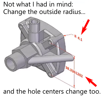
I open up Creo Parametric, and load up a part model.  Not too complex — some bosses, holes, and a bunch of blends.  I select a blend (or “round,” to use PTC parlance), then click and drag its resizing handle.  And wait.  And wait.  Eventually, after several seconds, the blend resizes.   I wait some more, and the blend resizes again.  Ad nauseum.

Why so slow?  Because Creo was recalculating the blend on the fly, as I was dragging.  Since the blend was in the middle of the feature tree, with a bunch of other dependent geometry, each time I moved the cursor, it had to do a very time consuming recalculation.  The right way of resizing the blend would have been to click on the blend radius text, and type in a new value.  Presto… the blend is resized exactly as I wished.  Alternatively, I could have used Creo’s flexible modeling tools, which would have recalculated the blend more quickly (though, when I tried to interactively drag the blend radius using flexible modeling, I still found the dynamic response to be unsatisfying.)

Is there a way to fix the problem I’ve described?  Yes.  Were I moving a boss across a surface that forced topological changes, Creo would have switched to a simplified representation of the boss, rather than recalculating it accurately on the fly.  So, Creo does know how to adjust it’s dynamic response depending on the needs of the situation.  It just doesn’t do it with blends.

The point of talking about this isn’t to beat up PTC. Other CAD vendors have similar problems. Creo is a very powerful product, and expert users can make it sing.  But put a user with a black thumb in front of it, and they’ll often do things that will bring it to its knees.

If PTC were building Creo expressly to satisfy expert users, the kind of experience I’ve just described wouldn’t be an issue. Expert users are smart enough not to do dumb things.  Yet, PTC is going to increasingly find that its products are used by normal folks (not Pro/E gurus), who are less likely to understand the program’s nuances, and who are less likely to be accepting of its quirkiness.  It’s important to get the little details right, so that all users, and not just the experts, can get the most out of their CAD programs.


Filed Under: 3D CAD Package Tips, Evan Yares, Pro/Engineer Tagged With: cad, Creo, Evan Yares, PTC, Usability

Creo 2.0 is near

March 2, 2012 By Evan Yares 1 Comment

PTC will soon be releasing Creo 2.0, and, in anticipation of this, invited me (along with three other blogger/editors) to their corporate headquarters for a preview. Unlike a formal release presentation, which would be heavily scripted, our experience was much more extemporaneous. We got to see a good chunk of what’s new, hear about PTC’s underlying goals, and even talk about things we thought they should be doing better.

What is Creo?

Creo was rolled out in the Fall of 2010. It was, at the highest level of abstraction, a bet-the-company rethink of PTC’s CAD strategy, based on a recognition that not all users (or enterprises) have the same needs.

While I can’t say, with certainty, what brought on this revelation, I can speculate that PTC’s 2007 acquisition of CoCreate was a big eye opener. It doesn’t take a genius to figure out that PTC’s legion of salespeople would have swarmed into CoCreate’s 5,000 customer accounts, seeking to convert those people to Pro/E users. Like that was ever going to work.

The reason people (and companies) used CoCreate software was precisely because it was not Pro/E (or any other history-based solid modeler.) CoCreate’s dynamic modeling (more commonly called direct modeling these days) was comparatively easy to use, especially for people who weren’t CAD gurus. Companies with product lines that fit within the capabilities that CoCreate offered had no motivation to change at all. CoCreate customers that needed history and parametrics in their CAD software had long since moved on to other tools (including Pro/E).

I imagine that a number of CoCreate customers took the time to explain to PTC management why dynamic modeling fit their needs so well. At the same time, PTC management was likely watching the former CoCreate marketing people (who now worked for them) telling a compelling story that didn’t exactly jibe with the PTC’s historical “parametrics will solve all your problems” message.

What to do? How to rationalize these seemingly irreconcilable things? The only reasonable answer is to offer customers what they want. For PTC, this required a new strategy: Offer a range of products sharing a common data model and a common user interface design, and allow users to choose whether they want to use history-based, direct, or any other form of modeling that might come along in the future.

It’s a good vision. But getting there is the challenge.

The first phase in the Creo strategy was launched, with quite a bit of fanfare, in the Fall of 2010. The next phase was originally due to launch in the Fall of 2011. It’ll launch next month.

I can’t give PTC any grief about being a few months late in shipping, given the immensity of the task before them. Taking several very disparate and complex products and merging them into a family of interoperable apps is not easy. Truth is, CAD is hard. Developing a professional CAD system is about an order of magnitude harder than, for example, developing a product such as Microsoft Office.

It’s going to take some time for PTC to fully deliver on the Creo vision. No problem with that, if they really deliver what users need.

Creo 2.0

I’m not going to do a review of Creo 2.0, or even tell you in any detail about what’s new in it. What I will say is that it looks like PTC is making solid progress, and is delivering useful capabilities that will help their users to get their jobs done better.

In the pantheon of Creo products, Parametric (formerly known as Pro/E), and Elements/Direct (formerly known as CoCreate) are maturing nicely. Creo Direct—the new product that essentially merges Pro/E and CoCreate capabilities—is taking some time, if only because it’s a much bigger job. Users with a long history (so to speak) with CoCreate should look carefully, to see whether Creo Direct has reached their particular threshold of “good enough.”

The big news in Creo 2.0, beyond maturation, is PTC’s delivery on their AnyBOM strategy. They are shipping the Creo Options Modeler, which works with Windchill to support assemble-to-order processes in a way that PTC’s largest customers (e.g., Caterpillar) will certainly appreciate.

PTC will be talking a lot more about Creo 2.0 in the very near future. For now, what I can say is this: It looks good so far.

PTC www.ptc.com


Filed Under: Evan Yares, Featured, News, Pro/Engineer, PTC News Tagged With: AnyBOM, Creo, Direct, Evan Yares, Parametric, PTC

The one peripheral 3D CAD users need

February 28, 2012 By Evan Yares 2 Comments

A 3d controller.  If you do production 3D CAD work, and you don’t have one, you’re running with one hand tied behind your back. So to speak.

Here’s an amateurish video I shot at SolidWorks World with Mark Driscoll, of 3Dconnexion, showing their new SpaceMouse Pro.


3Dconnexion

Filed Under: 3D CAD Package Tips, CAD Hardware, Evan Yares Tagged With: 3dcad, 3Dconnexion, Evan Yares, Mark Driscoll

SolidWorks V6 is not SolidWorks

February 22, 2012 By Evan Yares 12 Comments

Two years ago, at SolidWorks World (the show) SolidWorks (the company) showed what appeared to be the next generation of SolidWorks (the software): SolidWorks V6 (also software.)

SolidWorks (the company) got major flak from bloggers concerned that SolidWorks V6 (the software) would replace SolidWorks (the software.)

This year, at SolidWorks World (the show), Dassault Systèmes SolidWorks (as the company is now known) didn’t talk much about SolidWorks V6 (the product), other than to say that they’d talk about it in 2013.

Now that we’ve got that all clear, let’s talk about what matters: SolidWorks V6 is confusing branding. It confuses not only users, but even pundits who write about CAD software.

My understanding, after talking to company representatives at SolidWorks World, is that SolidWorks V6 is the name for not just one product, but a future series of products. Those products may incorporate some existing SolidWorks technology, but they’ll be based largely upon CATIA and ENOVIA V6 technology. Because they’ll use the CGM modeling kernel (which was originally written for CATIA V5), they’ll likely be more compatible with CATIA than with today’s SolidWorks.

It makes sense that Dassault Systèmes would want to leverage the strength of the SolidWorks brand for this upcoming series of products. The SolidWorks brand is one of the strongest in the MCAD world. If SolidWorks V6 were actually based on, and entirely compatible with, SolidWorks—the name might fit. But it’s not, and it doesn’t.

The SolidWorks V6 name creates unnecessary fear, uncertainty, and doubt among SolidWorks users who are concerned that they’ll be forced to transition from a CAD program they know and (sometimes) love to this new technology, whether they want to or not.

What’s particularly unfortunate is that, if Dassault Systèmes had originally used a code name for the technology instead of calling it SolidWorks V6, they never would have created this whirlwind of FUD among their users. People might have seen it as just what it is: A really interesting future product, that they might want to add to their portfolio of CAD tools some day (when it’s ready.)

The bottom line is that the new technology called SolidWorks V6 isn’t SolidWorks, and won’t replace SolidWorks. According to Fielder Hiss, SolidWorks VP of Product Management, the development team working on SolidWorks 2013 is even larger than the teams that worked on previous versions.

The real SolidWorks—the CAD program now used by about 1.7 million people—is going to be around for a long time.

Filed Under: Evan Yares, Featured, SolidWorks, SolidWorks News & Events Tagged With: Catia, Dassault Systemes, ENOVIA, Evan Yares, SolidWorks, V6

Hot rod engineering workstations

February 20, 2012 By Evan Yares Leave a Comment

When I was barely a teenager, in the early ’70s. I became interested in car magazines. In the back of some of those magazines, I’d often see ads for a company called Baldwin/Motion Performance. They sold brand new hot-rodded Camaros that were guaranteed to run 11.50 second or faster quarter miles at the drag strip. Baldwin/Motion Performance Camaros represented the epitome of tuner-built hot rods. They were fast enough that, according to Super Chevy magazine, you could buy one, and, with no further tuning, win the A/MP class at the Winternationals.

During the same period, other companies also sold fast Camaros. Though GM’s official policy in the late 60’s and early 70’s was that they didn’t support drag racing, there was a way to get nearly drag-ready cars, if you knew the trick. A few dealers, notably Yenko Chevrolet, managed to get Chevrolet to install Corvette 427ci L-72 engines in Camaros, through the “central office purchase order” process. These factory hot rod COPO Camaros came with a full factory warranty. Nearly perfect examples have sold for over $2.2 million USD at auction.

Muscle cars have little to do with CAD, but I was reminded of these cars, at least by analogy, when I was at the SolidWorks World 2012 show, in San Diego, last week.

While there, I attended a press conference announcing HP’s new Z1 engineering workstation. This machine is sort of analogous to a factory hot rod. It comes with a stunning 27” built in display, a quad-core Intel Xeon processor, NVIDIA Quadro graphics, and uses ECC (error correction code) memory—which is particularly desirable for critical engineering software applications (See Wikipedia’s entry on ECC memory for background on this.)

There’s no doubt that the Z1 costs more than a typical commodity PC. But, for people doing serious CAD, CAE, or CAM work, the performance and reliability the system offers is worth the premium.

While at SolidWorks World, I also had a chance to chat with Rick Krause, CEO of BOXX Technologies. BOXX makes what could be considered the equivalent of a tuner-built hot rod. Their 3DBOXX 3970 XTREME workstation is designed to provide the best performance possible for serious 3D CAD work. That is, it’s performance isn’t tuned for doing spreadsheets and web browsing (which benefit from multiple core processors), it’s tuned for doing serious CAD work (which requires fewer, but faster cores.)

Let’s go back to the car analogy: Yenko Chevrolet sold stock Camaros, with the biggest and best engines GM offered. Baldwin Chevrolet sold hot-rodded Camaros, also with the biggest and best engines GM offered, but tuned to put out over 500+ horsepower (while still being streetable.)

The HP Z1 engineering workstations use Intel’s biggest and best processors. The BOXX XTREME workstations also use Intel’s biggest and best processors – tuned (overclocked) for the most horsepower.

BOXX doesn’t really like to use the work “overclock,” because it implies that they’re pushing the processor past it’s design spec. BOXX works closely with Intel, to make sure they stay within the processor design specs. Since they use liquid-cooling, they can push the processor faster, without reliability problems. Their workstations are backed-up by a 3 year warranty, and, in their history of selling overclocked systems, they’ve never experienced a processor failure.

If you’re a serious CAD, CAE, or CAM user, and you can out-run your current computer, you need to take a serious look at getting a factory-built or tuner-built hot rod computer.

HP Z1 Workstation

BOXX Technologies 3DBOXX 3970 XTREME Workstation

 Photo courtesy Baldwin-Motion


Filed Under: CAD Hardware, Evan Yares Tagged With: BOXX Technologies, cad, CAE, cam, Engineering Workstation, Evan Yares, HP

Primary Sidebar

3D CAD NEWSLETTERS

MakePartsFast

Follow us on Twitter

Tweets by 3DCADWorld

Footer

3D CAD World logo

DESIGN WORLD NETWORK

Design World Online
The Robot Report
Coupling Tips
Motion Control Tips
Linear Motion Tips
Bearing Tips

3D CAD WORLD

  • Subscribe to our newsletter
  • Advertise with us
  • Contact us
Follow us on Twitter Add us on Facebook Add us on LinkedIn Add us on Instagram Add us on YouTube

3D CAD World - Copyright © 2021 · WTWH Media LLC and its licensors. All rights reserved.
The material on this site may not be reproduced, distributed, transmitted, cached or otherwise used, except with the prior written permission of WTWH Media.

Privacy Policy