• Skip to primary navigation
  • Skip to main content
  • Skip to primary sidebar
  • Skip to footer

3D CAD World

Over 50,000 3D CAD Tips & Tutorials. 3D CAD News by applications and CAD industry news.

  • 3D CAD Package Tips
    • Alibre
    • Autodesk
    • Catia
    • Creo
    • Inventor
    • Onshape
    • Pro/Engineer
    • Siemens PLM
    • SolidWorks
    • SpaceClaim
  • CAD Hardware
  • CAD Industry News
    • Company News
      • Autodesk News
      • Catia News & Events
      • PTC News
      • Siemens PLM & Events
      • SolidWorks News & Events
      • SpaceClaim News
    • Rapid Prototyping
    • Simulation Software
  • Prototype Parts
  • User Forums
    • MCAD Central
    • 3D CAD Forums
    • Engineering Exchange
  • CAD Resources
    • 3D CAD Models
  • Videos

Pro/E

How Whirlpool uses PTC CAD and PLM technology

June 7, 2012 By Evan Yares 4 Comments

Whirlpool Corp's Maytag Maxima seriesHome appliances aren’t what they used to be. Consider, for example, washers and dryers. At this week’s PlanetPTC conference, Fred Bellio, CIO of Whirlpool’s Global Product Organization, and Jeff Burk, Director of Whirlpool’s Constellation Program Management Office, described some of the complexities of his company’s Maytag Maxima line of washers and dryers. Washers and dryers from 50 years ago (when my mother was doing the family’s laundry) were mostly mechanical, with an electric drive motor, a timer, and a few switches, solenoids and relays. The Maxima line are about one-third mechanical, one-third electrical/electronic, and one-third software.

Who would have guessed that a clothes washer could have a million lines of software source code, and use WI-fi for remote diagnostics (and even electrical load shedding?)

Whirlpool is the world’s #1 major appliance company, with $19 billion in revenue, and around 70,000 employees. Its products are developed globally, and sold in over 170 countries. While it may not face the same challenges as large automotive or aerospace companies, that doesn’t mean that it’s got things easy when it comes to product development.

Whirlpool’s PLM strategy

To continue to be competitive in the appliance business, Whirlpool needs to implement a top-notch product development process. The Whirlpool program chartered to deliver that process is code named Constellation.

Constellation’s goals are to:

  • Leverage Whirlpool’s global footprint and scale,
  • Enable end‐to‐end lean product development,
  • Enhance collaboration across functions, geographies, & supply chain, and,
  • Provide a real time single source of product information.
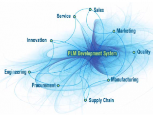
Whirlpool PLMThe Constellation program provides Whirlpool with a year-by road-map for implementing PLM technology. This year there are projects related to CAD, core PLM, design quality, cost management, product & portfolio management, service, strategic sourcing, and product quality. It’s not a trivial amount of work. (You can look at Whirpool’s PlanetPTC presentation on Constellation here.)

Ultimately, the benefits Whirlpool hopes to gain include:

  • Shorter product development cycles,
  • More consumer relevant innovation,
  • More product variants from fewer platforms, and,
  • Best cost and best quality position.

Whirlpool and PTC

Whirlpool has been a long-term PTC customer, first using Pro/E in 1986, and standardizing on it in 1990. The company entered into a strategic relationship with PTC in 2010, and currently uses a wide variety of PTC products, including ProE/Creo, Windchill ProjectLink, Windchill PDMLink, WQS, MathCAD, Integrity, PPMLink, Arbortext, Isodraw, and Product View.

My sense is that Whirlpool is a very good example of an ideal PTC customer. Their particular combination of needs are a great match for PTC’s technology. (That may be because PTC pays attention to their customers’ needs when planning their technologies.) Two PTC technologies of special note for Whirlpool are likely to be application lifecycle management (ALM), and service lifecycle management (SLM.)  I’ll be writing more about those two technologies in the near future.

While you could make an argument that Whirlpool could be as well-served by any number of other CAD programs (including SolidWorks, Inventor, and Solid Edge) as they are by ProE/Creo, I think there’s an equally strong (or  stronger) counter-argument. Creo 2.0 includes some capabilities of great value to a company such as Whirlpool. The thing that comes to my mind first is integrated parametric, direct, and organic subdivision surface shape modeling. But the hot ticket is the new Creo 2.0 Options Modeler, which, when coupled with Windchill, is the no-brainer choice for building multiple product variants on a single platform.

Even good examples have flaws

Listening to Jeff Burk describe Whirlpool’s Constellation strategy at the PlanetPTC conference, it occurred to me that the company does seem to have a solid grasp on where it’s going with PLM. I’d expect this: Bellio was the PLM Practice Director at Mercury Marine’s PLM Services group (a company that Siemens PLM highlighted at their recent customer conference.) He also worked in PLM strategy and deployment at Bombardier—and aerospace is where the rubber meets the road for PLM (to strain a metaphor.) Burk has 25 years at Whirlpool, and knows what makes the company tick.

Still, I was curious: Whirlpool has been using Pro/E for 26 years. Do they have the CAD portion of their PLM strategy down? I asked Bellio and Burk about three product design-centric best practices that are generally thought to make a big difference in time to market, cost, and quality: systems engineering, model-based development (e.g., no drawings), and up-front CAE.

Bellio and Burk agreed that each of these are of real value, and that Whirlpool is very interested in them. But, Whirlpool isn’t doing any of them yet.

Why? Start with model-based development: (MBD): It’s simply difficult to change from a drawing-centric to a model-centric culture. Even if good software tools for doing 3D GD&T are available (and they are available for ProE/Creo, both from PTC, and from third-parties such as Sigmetrix), engineers are comfortable with drawings, and aren’t inclined to change, if they can help it. The only industries in which there is widespread adoption of MBD are aerospace and, to a lesser degree, automotive. (This will change over time: MBD is a hot industry trend.)

Similarly, implementing systems engineering and up-front CAE require cultural and process changes that are not natural for CAD users (and particularly ProE users) who’ve invested a lot of time and effort in learning how to do it the way they’re doing it now. You can’t just “install” these practices in a product development process, and expect everyone to jump into using them.

This stuff takes time, and commitment

Looking at Whirlpool’s example, I wonder: do any of PTC’s customers take “full advantage” of all (or even most) of the technology that PTC has to offer? I suspect the answer is “no.”

As a start, PTC offers a lot of technology. A lot of it overlaps with technology offered by competitive companies—and many customers use a mix of tools from a number of suppliers.

Yet, beyond issues of scale, the process of implementing PLM in a company, whether small or large, takes time and commitment, no matter which technology suppliers you use.   There is no magic bullet that will make the process easy.  My sense is that the folks at PTC are focused on doing what they can to make the process easier.  While I still think PTC has a long way to go in making their technology more accessible for non-experts, I’ve seen enough progress that I’m encouraged.

Filed Under: Creo, Evan Yares, Featured, News, Pro/Engineer, PTC News Tagged With: Creo, PLM, Pro/E, PTC, Whirlpool, Windchill

Autodesk provides real-time DFM for plastic part design

April 3, 2012 By Evan Yares 1 Comment

There’s a lot of benefit to be had by doing manufacturability analysis (DFM, Design for Manufacturing) early in the design process, rather than waiting until later, when design changes are far more expensive.

A couple of years ago, Autodesk Labs previewed a product, Project Krypton, which ran inside of 3D CAD programs (including Autodesk Inventor, DS SolidWorks, and PTC Pro/E), and gave real-time feedback on manufacturability, cost, and sustainability of plastic injection molded parts.


Project Krypton has now reappeared, in commercial form, as Autodesk Simulation DFM (Design For Manufacturing.) It works as a plug-in, running in a number of versions of Inventor, Inventor LT, Wildfire, Creo, and SolidWorks. It is available as a subscription benefit for Autodesk Simulation Moldflow Adviser 2013 subscribers, or as a stand-alone product, at US$2,000 for a license to run on any of the supported CAD platforms.

It’s reasonable to argue that engineers who are designing plastic parts should know enough to be able to recognize manufacturability, cost, or sustainability problems. And, if they don’t, they should take the time to learn (for example, by taking a few hours to read any of the many freely available books on the subject, such as General Design Principles for DuPont Engineering Polymers.) Even though that argument is reasonable, it doesn’t recognize human nature. People, even engineers who should know better, don’t always take the time to “read the manual.” Often, it makes sense to build the “manual” into the tools that engineers use every day. Simulation DFM does that, and quite a bit more.

For inexperienced designers, Simulation DFM provides quick feedback to help them avoid rookie mistakes. It’s sort of like an “idiot light” on a car’s dash, that warns you when something is wrong. And while old-hands might say they prefer gauges to idiot lights, experience has shown that idiot lights are useful to experts (even F1 drivers and fighter pilots) for catching their attention, and getting them to actually look at the gauges.
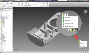
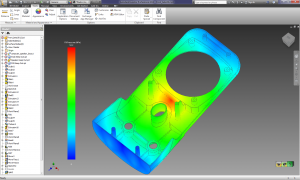
Simulation DFM doesn’t require that users have any background in molding simulation. It uses “green is good, yellow is not so good, and red is bad” indicators to identify potential manufacturing, cost and sustainability issues, showing the source and location of the problem. Any issues that pop-up can be expanded upon, to provide more detail on the exact source of the problem, even showing, for example, mold filling analyses.  The software requires no additional training, and doesn’t require much user input.

The open question with Simulation DFM is “how good is it?” Since it’s based on the Autodesk Moldflow simulation engine, it should be quite good, even for relatively complex parts (though it doesn’t support multi-body parts.) Yet, even if its capabilities were modest, it would still be of value, in either helping beginning designers to learn good design practice, or helping old-hands catch mistakes they might have otherwise missed.

As an engineer, I’ve long had the habit of using the “anything I can see” test to evaluate the usefulness of software. I look around the room, looking at anything I see, and ask myself “would this software have helped the engineers who designed these things?” In this case, as I sit in my office, I can see at least 20 items (without even turning to look behind me), each with multiple injection molded parts, that would have been quicker, easier, and less-expensive to design, had their engineers had access to up-front DFM software, such as Autodesk Simulation DFM.

The most significant benefit of Autodesk Simulation DFM comes not from its detailed capabilities, but rather from its clean integration into the design workflow. A user need not press a button, or take any specific action when designing a plastic part to benefit from it. All they need to do is notice, as they design, whether the software has picked up any obvious red-flags.

That Autodesk decided to make Simulation DFM available for Pro/E, Creo, and SolidWorks (as well as Inventor) shows that rational minds sometimes do prevail: There are untold thousands of PTC and SolidWorks customers who design plastic injection molded parts, and who are unlikely to switch primary CAD tools any time soon. The challenge Autodesk is going to face is in getting Simulation DFM in front of those users (since PTC and SolidWorks sales reps and dealers are not likely to recommend it.) Maybe not so much of a challenge: Many of Autodesk’s existing Moldflow customers are Pro/E and SolidWorks users.

There’s a certain charm to software that does something of great value, but does not impose any extra demands on its users. Autodesk Simulation DFM looks like it may be that kind of product.

Autodesk www.autodesk.com

Autodesk SimSquad simsquad@autodesk.com

Filed Under: Autodesk, Autodesk News, Creo, Evan Yares, Featured, Inventor, News, Pro/Engineer, Simulation Software, SolidWorks Tagged With: Autodesk, CAE, Creo, DFM, Inventor, Moldflow, Pro/E, simulation, SolidWorks

Software for manufacturing

August 23, 2011 By Laura Carrabine Leave a Comment

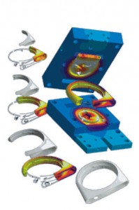
Sigmasoft simulates the following processes: filling, packing, cooling, venting, shrinkage, warpage, stress, ejection, post molding, hot runners, multi-cycle, multi-component, and insert over-molding.

Sigmasoft filling and packing simulation predicts temperatures, pressures, velocities, crystallization, and shearing at any location at any time to determine manufacturability and ensure a balanced mold design. Weld lines, sink marks, voids, and air traps are also valuable outputs to eliminate the potential for part defects.

The thermal distribution inside an injection mold depends on many factors. In the same way as the polymer flows three dimensionally into the cavity, the heat also flows three dimensionally between inserts, part, mold, and thermal control. A multi-cycle analysis enables you to simulate the quasi-stationary state of a m old including all local temperature differences and consequently to perform a much more precise filling simulation based on the steady state temperature distribution. Sigmasoft accurately calculates the complex thermal distribution in the mold coupled with polymer flow.

The software simulates the impact of the ejection system on the part and offers insight into the ejection system design. Ejection forces are predicted to understand their impact on final part quality. The ejection system may also be evaluated to determine the porper quantity of ejector pins.

Proper venting is critical to the injection molding process. Without proper venting, quality and flow imbalances are common issues. Sigmasoft lets you model vents into the simulation to optimize location and size, and view the impact of trapped air on the flow front. View trapped air pockets, air pressure, and air temperature in the cavity.

The software predicts post-ejection stress relaxation and crystallization of the part which often provides a more accurate warpage prediction. A second heat cycle may also be simulated, taking into account the entire process history.

3D CAD models of the part geometry and the entire mold if needed can be imported directly into Sigmasoft in multiple formats including STEP, STL, SAT, Pro/E, or Catia. The software also includes tracer particles to help visualize what is happening behind the flow front. These tracers are shown during the filling, packing, and cooling processes.

Sigmasoft

www.3dsigma.com

Filed Under: Simulation Software Tagged With: 3D CAD, analysis, Catia, plastic injection molding, Pro/E, Sigmasoft, simulation, warpage

Aston Martin Racing selects Creo Elements/Pro and Windchill to design and manage development of next generation vehicles

March 2, 2011 By Laura Carrabine Leave a Comment

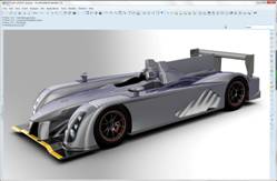
PTC announced that in an extensive benchmark process Aston Martin Racing selected and implemented Creo Elements/Pro for the 3D CAD design of its racing vehicles and Windchill for product lifecycle management (PLM) in its race car division.

Aston Martin is the only manufacturer that produces a car to compete in every category of the FIA GT Championship sports car racing series. Models range from modified standard vehicles in the GT4, GT3 and GT2 classes – including the high-performance V12 – to the 6.0 litre 600 BHP DBR9 in the GT1 class and the Le Mans prototype LMP1 Aston Martin.

Aston Martin Racing has moved away from its previous third-party chassis strategy to develop its next generation LMP1 from scratch. This new racing vehicle is now being designed and engineered from the ground up using Creo Elements/Pro and Windchill to manage the development process. In addition to the designers, the purchasing department uses Windchill for its request for quotation process, enabling collaboration with suppliers.

PTC                              

www.ptc.com

Filed Under: 3D CAD Package Tips, CAD Blogs, Pro/Engineer, PTC News, PTC/CoCreate Blogs Tagged With: 3D CAD, Aston Martin, Creao Elements, LeMans, Pro/E, PTC, Windchill

FIRST and PTC expand collaboration to bring FIRST Tech Challenge to India, China, & Eastern Europe

March 1, 2011 By Laura Carrabine Leave a Comment

FIRST (For Inspiration and Recognition of Science and Technology), a not-for-profit organization that inspires young people’s interest and participation in science, technology, engineering and math (STEM) announced that, in cooperation with PTC, it expanded the international rollout of the FIRST Tech Challenge (FTC) program to India, China, and Eastern Europe. PTC is also a top level Crown Supplier for FIRST and the FTC CAD and Collaboration Sponsor for the 2010-2011 season.

The dates for the 2011 competitions have been set for April 2 (Bucharest, Romania); April 23 (Shanghai, China); and August 15 (Mumbai/Delhi, India).

In preparation for this year’s FRC and FTC seasons, PTC completed over 40 hands-on workshops for students, teachers, volunteers, and mentors to learn 3D design and collaboration technology. More than 800 teams have signed up for free PTC software, including Creo Elements/Pro, Mathcad, and Windchill. Students and teachers may download PTC software at www.ptc.com/go/softwareforfirst.

PTC also modeled the 2011 FTC and FRC Kit-of-Parts (KoP) in Creo Elements/Pro, which each team can use to speed the design of its robot. The KoP may be downloaded at www.ptc.com/go/firstkop.

FIRST and PTC invite interested parties who would like to participate in these international programs to contact Jordan Cox, PTC’s FIRST Program Manager, at jocox@ptc.com.

PTC

www.ptc.com

Filed Under: 3D CAD Package Tips, CAD Blogs, Pro/Engineer, PTC/CoCreate Blogs Tagged With: Creo, FIRST, Pro/E, PTC

Vero help with Artega GT ‘supercar’ production

July 13, 2010 By Laura Carrabine Leave a Comment

DECS GmbH are specialists in the design and manufacture of interior and exterior trim composite components for the automotive industry. Reference customers include Audi, BMW, Lamborghini, Mercedes, and Porsche. DECS GmbH embraces technology and firmly believes in process optimization. It is a combination of these factors that helped their latest project, the Artega GT succeed, and cause a stir in the automotive world.

The Artega GT is a mid-engined, rear wheel drive, high-performance sports car designed by Henrik Fisker, the man responsible for the much celebrated Aston Martin Vantage and the sweeping lines of the BMW Z8. The two-seater GT has an aluminum space frame and carbon fiber reinforced body. Providing the power is a Volkswagen-sourced 3.6L V6 engine reaching 60mph in less than five secs.

Within the framework of this project, DECS GmbH contributed to the manufacture of the front bonnet, tailgate, and roof.  Ulrich Krämer, Managing Director of DECS GmbH explains how the project started. “Artega originally contacted us because we have been involved in a number of projects with other prestige automotive clients and possess the skill and knowledge required for the development of composite components. For the initial pilot project, we first created five parts using a prototype tool. We were then invited to participate in the second phase in which we produced a pre-series set of tooling for the front bonnet and tailgate for testing. After successful pre-series testing, we now manufacture the complete suite of production parts for the front bonnet, tailgate, and roof.”

DECS GmbH produces its polyurethane-based composite components using a honeycomb core. This is especially relevant in the development of automotive interiors as the potential weight reduction is extremely attractive to car manufacturers. Natural fiber-reinforced polyurethanes are being used more and more in the automotive industry and it is now possible to produce parts with wall thicknesses of 1.5 – 2.0 mm – depending on the unit weight of the natural fiber mat used. These end products weigh about 45% less than products created using conventional injection molding materials.

One example of process optimization is the use of Huber & Grimme gantry milling machines, which are equipped with efficient two shaft spindles and tandem work-tables for multi-axis part trimming. Once the body panels are removed from the tool, they are placed onto jigs and fixtures for part trimming and additional CAM operations. All 5-axis operations are programmed using VISI Machining from Vero Software and posted using a Siemens 840D controller. Due to the complex nature of multi-axis machining, NC programs are also simulated prior to running on the shop floor. The simulation checks against the physical machine limits and ensures process-safe tool paths.

The relevant jigs and fixtures are also designed using VISI software and produced at DECS. “VISI is the ideal tool for the construction of the trimming jigs”, explains Krämer. “One advantage is the ability to constantly switch between solid and surface technologies. This is vitally important to us and allows us to follow a flexible design path. VISI provides interfaces to all the significant data formats such as CATIA, UG, Pro/E, STEP, IGES, and SAT and this allows us to handle our clients native CAD data with confidence.”

VISI has been in use at DECS GmbH since 2005 when the software was provided as a solution for simultaneous 5-axis milling to solve a problem that involved the complicated trimming of plastic parts with undercut positions that could not be could be processed with water-jets.

Vero Software
www.vero-software.com

Filed Under: 3D CAD Package Tips Tagged With: Aston Martin, Audi, BMW, cad, cam, Catia, DECS GmbH, Lamborghini, Mercedes, Porsche, Pro/E, UG, Vero, VISI Machining, Volkswagen

Primary Sidebar

3D CAD NEWSLETTERS

MakePartsFast

Footer

3D CAD World logo

DESIGN WORLD NETWORK

Design World Online
The Robot Report
Coupling Tips
Motion Control Tips
Linear Motion Tips
Bearing Tips

3D CAD WORLD

  • Subscribe to our newsletter
  • Advertise with us
  • Contact us
Follow us on Twitter Add us on Facebook Add us on LinkedIn Add us on Instagram Add us on YouTube

3D CAD World - Copyright © 2022 · WTWH Media LLC and its licensors. All rights reserved.
The material on this site may not be reproduced, distributed, transmitted, cached or otherwise used, except with the prior written permission of WTWH Media.

Privacy Policy