• Skip to primary navigation
  • Skip to main content
  • Skip to primary sidebar
  • Skip to footer

3D CAD World

Over 50,000 3D CAD Tips & Tutorials. 3D CAD News by applications and CAD industry news.

  • 3D CAD Package Tips
    • Alibre
    • Autodesk
    • Catia
    • Creo
    • Inventor
    • Onshape
    • Pro/Engineer
    • Siemens PLM
    • SolidWorks
    • SpaceClaim
  • CAD Hardware
  • CAD Industry News
    • Company News
      • Autodesk News
      • Catia News & Events
      • PTC News
      • Siemens PLM & Events
      • SolidWorks News & Events
      • SpaceClaim News
    • Rapid Prototyping
    • Simulation Software
  • Prototype Parts
  • User Forums
    • MCAD Central
    • 3D CAD Forums
    • Engineering Exchange
  • CAD Resources
    • 3D CAD Models
  • Videos

simulation

Tech Innovations Spurring Revival of U.S. Manufacturing

July 7, 2014 By Barb Schmitz Leave a Comment

A lot has been written in the press lately about the comeback of U.S. manufacturing. Several factors come into play here. Cost creep in China–due to rising inflation and wage expectations–means that as soon as 2015 the U.S. could be in cost parity with Chinese manufacturing.

Fears regarding IP security have also forced manufacturers to rethink offshoring strategies that once promised competitive cost advantages. Both of these trends are fueling what’s being called the “nearshoring” or “inshoring” trend, that is, companies bringing manufacturing back to the U.S.

Major companies, such as Ford, Apple, Caterpillar, and GE have moved nearly 20,00 manufacturing jobs back to the U.S. from Asia and Mexico with the last couple of years.

Another advantage of having of onshore manufacturing is that having the capability to manufacture close to where customers are located can increase customer responsiveness and decrease turnaround times, making the supply chain more predictable.

GE's Appliance Park in Louisville, KY, is being revamped, thanks to an $800 million investment in jobs, products, and manufacturing to build better, more efficient dishwashers.
GE’s Appliance Park in Louisville, KY, is being revamped, thanks to an $800 million investment in jobs, products, and manufacturing to build better, more efficient dishwashers.

Another factor contributing to an uptick in U.S. manufacturing is that the fact that natural gas prices have been reduced by two-thirds since 2008, making the U.S. more competitive for gas-intensive industries, such as petrochemicals and fertilizers.

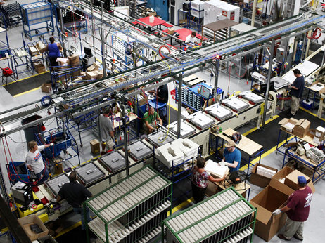
U.S. Manufacturing Benefits from Tech Innovations

Perhaps the biggest factor, however, is the wave of technology advancements (digitization, data analytics, advanced automation, Internet of things and additive manufacturing) that are changing the landscape for U.S. manufacturers. Many of these advancements are driven by software innovations.

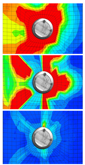
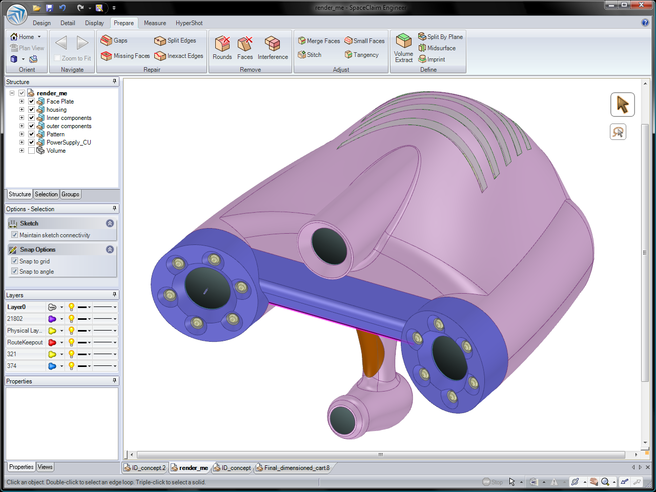
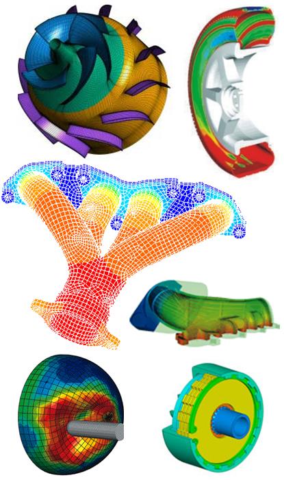
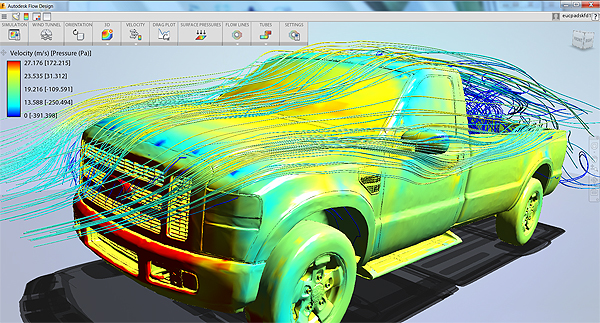
CAD and simulation software continue to improve manufacturers’ ability to create high-quality products faster than ever, cutting out expensive physical prototyping that in turn reduce design costs.

New additive manufacturing and 3D printing applications are making it easier for more players to become innovative manufacturers without the traditional constraints of high-volume manufacturing. Crowdsourcing and crowdfunding sites and platforms are also encouraging more would-be inventors to enter the market.

Robotics are reducing the need for labor, again reducing the cost of manufacturing products. The ability to embed sensors through the whole system, link them through the “industrial Internet,” and extract insight from the data means that U.S. companies are now leading the world in accelerating product development cycles and delivering on the promise of mass customization.

What is the result of all these innovations? According to Mark Muro, senior fellow at the Brookings Institution, it means, “The game is now being played on American terms. Software and brilliant machines are erasing U.S. cost deficits and giving it a shot at lasting production leadership,” says Muro.

Barb Schmitz

Filed Under: News Tagged With: 3D printing, cad, manufacturing, simulation, software

Dassault Unveils 3D Simulated Heart

May 20, 2014 By Barb Schmitz Leave a Comment

In an exciting breakthrough in the study of heart disease and its treatment, Dassault Systèmes today announced its role in the creation of the world’s first realistic 3D simulation model of the human heart.

The model was developed by a multidisciplinary team of heart experts working to combat cardiovascular disease. The goal of the “Living Heart Project” is to develop better methods of diagnosing, treating and preventing heart conditions through personalized, 3D virtual models.

SIMULIA software used to create simulated heart model

At the center of the project is a comprehensive 3D heart model created by simulation experts at Dassault using its SIMULIA simulation software. The 3D heart model captures the electrical and mechanical behavior of the heart in a very realistic way.

Today, the lack of realistic 3D human models limits researchers’ ability to predict device behavior in humans. The Living Heart Project has attracted a multidisciplinary community of medical researchers, practitioners, device manufacturers and industry regulators who will have access to 3D computational models to accelerate the translation of research innovation into market-driven products and services.

By capturing a patient's beating heart in 3D, doctors can optimize treatment plans.
By capturing a patient’s beating heart in 3D, doctors can optimize treatment plans.

Using echocardiogram, MRI and CT scan images, along with cardiac research data, personalized 3D heart simulations will soon allow medical professionals to better understand the behavior of a patient’s heart without the need for additional invasive diagnostic procedures.

This realistic human heart simulation will not only become a valuable educational and translational tool to incite research innovation, but may also lead to accelerated regulatory approval cycles, reduced development costs for new and more personalized devices and will ultimately enable early diagnoses and improve treatment outcomes.

“The Living Heart Project is a leading example of the value and potential for realistic simulation to significantly impact healthcare in a positive way,“ noted Bill Murray, president and CEO, Medical Device Innovation Consortium. “The Living Heart Project is a model for how collaborations can work to advance regulatory science in the medical device industry and improve patient access to cutting-edge medical technology.”

Barb Schmitz

Filed Under: CAE, Company News, Dassault Systemes, News, Simulation Software Tagged With: Dassault Systemes, simulation

Autodesk Acquires NEi Nastran Solver

May 19, 2014 By Barb Schmitz Leave a Comment

It seems as it the rate of acquisitions and strategic mergers and partnerships is at a fevered pitch right now. In the 3D printing world, it seems like companies are gobbling up other companies nearly daily. The end result of acquisitions is often a mixed bag. Often promising technologies coming out of smaller companies seem to completely fall off the map when purchased by bigger brethren.

Simulation becomes important piece of product design puzzle

More and more companies are reaping significant time-to-market boosts and increased product quality benefits from using simulation tools earlier in the development cycle. By reducing the number of physical prototypes that need to be built, these same companies are also significantly cutting design costs and still designing better products.

Not longer the domain of analysts and specialists, mid-range simulation tools are increasing being targeted at design engineers using so-called mid-range CAD systems, such as Inventor, SolidWorks, Solid Edge and Creo.

Autodesk moves to add Nastran to its CAE lineup

Last week, Autodesk announced that it had acquired the Nastran solver from NEi Software. To be clear, this is not the Nastran that was based on the original NASA-sponsored code. NEi Nastran, however, is often benchmarked against the original Nastran as well as ANSYS and Abacus.

Though the company has yet to unveil its plans for the software, it is speculated that the company will add the solver’s powerful linear and nonlinear as well as dynamic response capabilities to the other solvers the company has acquired in recent years. These include those from Algor, Moldflow and CFDesign.

This image shows the behavior of a metal structure (top image) as well as the top layer matrix and fiber failure indexes of a composite structure (middle and bottom image).

Solvers are the brains behind CAE software. They solve huge matrices with various algorithms for memory management, matrix simplification and rearrangement, and convergence tolerances.

Not much as been released in terms of details of what Autodesk has in store for the NEi Nastran solver, which has been traditionally aimed at the high-end, nonlinear user base, not design engineers. As a result, many questions remain unanswered. Not only what are Autodesk’s plans with the solver but how will partner relationships be handled? What will happen to the employees at NEi?

We’ll have to stayed tuned for the answers to those questions, but this acquisition is yet more evidence of how simulation technology is posed to become a tool–and competitive weapon–that that every company will be deploying in the years ahead.

Barb Schmitz

Filed Under: News Tagged With: Autodesk, FEA, Nastran, simulation

ANSYS Acquires SpaceClaim

May 5, 2014 By Barb Schmitz Leave a Comment

Consolidation through strategic acquisitions is nothing new in the CAD world, though I must admit to being surprised by last week’s announcement that ANSYS, a world leader in simulation technology, had acquired SpaceClaim Corp. for $85 million in cash. The transaction closed on April 30.

SpaceClaim took the “direct” approach to 3D modeling

SpaceClaim introduced direct modeling to the masses with the introduction of SpaceClaim 2007 Professional back in 2007. SpaceClaim, which my colleague Josh Mings referred to as “the company slapping the history out 3D modeling,” was founded in 2005 by industry big-wig Mike Payne, who also helped start up PTC and SolidWorks. The goal was to offer a 3D modeling tool that could be used by more than just CAD experts.

ANSYS and SpaceClaim have partnered up in the past to offer customers ANSYS SpaceClaim Direct Modeler as an option to ANSYS customers. These users, who are mostly analysts, work in 3D but didn’t want to become experts in traditional, feature-based CAD systems. With the software, users could create and modify 3D geometry models without needing to learn the complexities of the CAD software.

The functions in SpaceClaim's Prepare tab make it easy to simplify, de-feature and prepare models for analysis in ANSYS Workbench and GAMBIT.
The functions in SpaceClaim’s Prepare tab make it easy to simplify, de-feature and prepare models for analysis in ANSYS Workbench and GAMBIT.

By enabling ANSYS users to create and modify 3D models, simulation can be done upfront in the product development process, where the biggest payoffs (performance, cost and time-to-market) can be realized. The vision of ANSYS has always been to enable companies to leverage the value of computer simulation early in the design process to predict how a product will perform in the real world.

By adding SpaceClaim to its product line, ANSYS customer will have a 3D direct modeling tool for creating new concepts and then performing simulation on those models to iterate and optimize product designs. In addition, because ANSYS has always been an essentially open platform and SpaceClaim’s solutions are also relatively CAD-neutral, users can modify geometries regardless of what system was used to create them.

Benefits of acquisition

* Acceleration of ANSYS’ technological product roadmap and long-time vision for Simulation Driven Product Development. SpaceClaim can help simplify and automate what has traditionally been a time-consuming process of preparing geometry for use in a simulation system, enhancing ease-of-use to help ANSYS accelerate product adoption and the growth of the simulation market overall. The transaction enables ANSYS to accomplish what would have taken the company many years (if ever) to develop alone.
* Enhanced customer offering through complementary technologies. The transaction enablesANSYS to provide its customers with a 3D direct modeling solution to author new concepts and then leverage simulation to iterate on these designs.
* Drives growth through an expanded customer base and cross-selling opportunities. The broad appeal of SpaceClaim’s technology can help ANSYS deliver simulation tools to any engineer in any industry – at the earliest stages of the design cycle – expanding ANSYS’ user base from analysts and expert users to 5 million design and systems engineers.
* Increased innovation. SpaceClaim’s flagship product is SpaceClaim Engineer, 3D direct modeler, and offers UI/UX design for both 3D applications and mobile devices.

Of those proposed benefits, I think the one that stands out as obvious is the fact that acquiring SpaceClaim expands ANSYS’ user base from analysts and expert users to five million design and system engineers. We’ll certainly be watching to see how this shakes and out and will keep you updated on any new product announcements made as a result of this union.

For more information, check out the official press release from ANSYS.

Barb Schmitz

Filed Under: CAE, News, SpaceClaim, SpaceClaim News Tagged With: ANSYS, Direct Modeling, simulation, SpaceClaim

Preparing Models for Simulation: Which 3D Modeling Paradigm is Best?

March 3, 2014 By Barb Schmitz Leave a Comment

Simulation technology has its origins in the labs of universities and specialists groups within the aeronautics and automotive industries. Today, however, simulation software has moved from research labs into mainstream product design and engineers and designers are increasingly using simulation tools to guide their design choices.

How simulation tools are used today

As designs progress throughout the development cycle, a sequence of decisions and adjustments are made, affirming that the design is on the right path. When used properly, simulation tools can help guide engineers on that path by providing with a way to make better decisions in order to design better products faster and at lower cost.

To make it easier to incorporate simulation into product development, many CAE programs are tightly integrated with CAD software. The integration of CAD and FEA enables engineers to test ideas, adjust designs, explore, and verify to confirm that designs are on the right track, minimizing the risk of flawed designs moving forward when changes are most costly.

FEA1

Preparing models for simulation

When models are ready to be simulated, engineers and designers often have to simply them in order to be able to perform simulations on them. During our recent “Pros and Cons of 3D Modeling Paradigms” webinar, the question of which 3D modeling technique works best when models are going to be simulated was posed to our speakers. I think their respective responses are worth sharing.

Chad Jackson, principal analyst, Lifecycle Insights.

I think that both those technologies (direct modeling and feature-based modeling) work with simulation but in two very different scenarios. I think with direct modeling, it helps you with simplification and abstraction of model prior to analysis. Now, if you try and do that through feature-based approaches, you can run into model failures and you have got to find the guy that originally designed it to really make progress there.

Direct modeling is a really good fit there if you’re looking at one model and you want to get it ready for simulation. However, there are a lot of organizations today that deal with a lot of variance of products or parts. Feature-based modeling is a great way to automate the generation of those variances and that applies to simulation as well when you look at things like design-of-experiment studies, optimizations and things like that. I think both have a fit but very different uses.

Dan Staples, vice president, Solid Edge Product Development, Siemens PLM.

The only thing I would add is that when you talked about the abstraction, and I think when you get to that it’s typically the analyst who is getting something from the designer and he needs to abstract it for purposes of analysis. The thing about direct modeling, in general, is it’s for someone who’s not a CAD expert and hasn’t been indoctrinated into the history tree and the recipe that most of us got indoctrinated into 10 or 15 years ago.

History-based modeling techniques are intuitive, but only because we had a beat into our heads for many years. Certainly, I think if you were to ask the average guy on the street or the guys who’s an analyst and not exposed to CAD on a daily basis in terms of modeling, it’s just a lot easier to approach the kind of changes you needed to make by using direct modeling.

Brian Thompson, vice president, Creo Product Management, PTC.

It’s not merely a matter of direct modeling style changes for purposes of the abstraction or for purposes of simplification, but it’s also the analyst who does his first round analysis. He gets a result and he realizes well, ‘I’ve got an issue with the stress here or there’ and the analyst then wants to go in and modify the the model, not for simplification or abstraction purposes, but because he’s got stress problem. He could go through the pain of going back and asking the engineer to make that change or he could maybe do some exploratory work with the model himself.

With direct modeling he doesn’t need to worry about the original design intent of the model. He can make direct modeling-based changes to the model in order to explore how to reduce the stress or how to change the natural frequency or whatever type of analysis he’s doing in order to achieve the design goal without having to cycle back through the person who understood the original design intent of the model. Lots of good reasons to use direct modeling there.

If you missed the “Pros and Cons of 3D Modeling Paradigms” webinar, you can watch it in its entirety here.

Barb Schmitz

Filed Under: Creo, News, Siemens PLM, Simulation Software Tagged With: simulation

5 Surprising 2014 Worldwide CAD Trends

February 28, 2014 By Barb Schmitz Leave a Comment

An interesting study has just been released by Business Advantage Group, a B2B research and consultancy based in the U.K. I thought some of the results of the survey were surprising and worth sharing. The company surveyed 409 CAD users and decision makers with the goal of identifying key trends in the CAD sector, both now and over the next five years. While certainly CAD vendors will find this information useful, I think that CAD users and their managers might find some of these trends useful as well.

CAD Trends 2014 Logo LP

Without further ado, let’s take a look at some of the more interesting results.

1. There’s still a large gap between technology use and awareness. According to the study, for 3D modeling technology, 81% of respondents were “aware” of the technology, but only 62% were actually using the technology. For simulation, nearly half (48%) of respondents were aware of the technology, but only 28% were actually using it. Due to all the recent buzz on 3D printing, 65% of respondents were aware of it, yet only 14% were using it. Though this isn’t particularly surprising since the 3D printing industry is still in its infancy, the gaps in both simulation and 3D modeling are more shocking since both are fairly mature technologies.

2. More people want mobile access to CAD. According to the survey, 21% of respondents are currently using some means of accessing CAD data on mobile platforms and that number is predicting to grow by 10% in the next year. In the Americas, that percentage is currently over a quarter of all respondents (26%). Look for growth in this area to be high in Asia Pacific with an 18% growth rate anticipated over the next year. For more on the the issues involved with Mobile CAD, see “Is CAD Becoming More Portable.”

3. Big data not a “big” deal yet. Despite a lot of media attention and making nearly everyone’s top tech trends list, big data apps still don’t seem too important to CAD users. Despited the touted benefits of mining big data, which include faster response times to market (45%), savings on cost (41%) and design time (32%), as well as design improvements (32%), according to the survey, only 3% of respondents are currently using data analytics applications and only a total of 4% will be predicted to do so within the next year.

4. CAD in the cloud will grow. While only a paltry 7% of respondents to the survey indicate that they currently using Cloud-Based CAD, that number is predicted to grow 9% over the next year and another 9% within the next five years. So within five years, a quarter of these respondents will be moving to the cloud for CAD. Benefits of cloud-based CAD seen as higher mobility (76%), increased storage capacity (36%), ease of updating software (35%) and cost reductions (33%).

5. Less overseas outsourcing of CAD-related jobs. It appears the trend of outsourcing CAD talent is waning. Currently 8% of respondents indicated that their respective companies are outsourcing CAD-related jobs overseas, and that number is only expected to rise by 1% within the next year. What was surprising was the fact that outsourcing CAD talent is more prevalent at large companies (14%) than smaller companies (4%).

To read the entire “Worldwide CAD Trends 2014 Survey Report,” download it here.
Barb Schmitz

Filed Under: CAD Industry News, CAE, News, Simulation Software Tagged With: 3D printing, cad, simulation

PDF3D Developers Release ParaView Plus for Visualizing Complex Data

February 4, 2014 By Barb Schmitz Leave a Comment

For many years, engineers and designers have struggled on the best way to safely share design data with others. Security is an issue. Bandwidth limitations yet another as files containing engineering data are often gargantuan. Yet another roadblock is all the various types of file formats that engineering data is saved in. On the CAD side, each system saves its data in different proprietary formats, making opening and using other’s CAD data problematic, at best.

PDF3D to the Rescue

PDF3D is a 3D visualization and technical publishing platform that offers engineers, scientists and developers a better way to communicate and share complex data and 3D models with others in a universally accessible format. The technology under the hood of PDF3D provides the fastest and easiest-to-use, high compressed 3D PDF conversion available for a wide variety of formats and tools, making it perfect for CAD users.

ParaView Plus facilitates visualizations of engineering data

After working closely with engineers in several industries, the developers of 3D PDF have released a new version of the ParaView plug-in for 3D PDF conversion. Called ParaView Plus, the open source app was designed to visualize both large and complex scientific data on super computers as well as laptops and PCs. The new app now offers animated, interactive 3D PDF publishing features, enabling engineers to better and more easily visualize complex simulation results and share them with others.

ParaView Plus plug-in enables engineers to visualize complex data in a wide range of files and formats, including 3D CAD, GIS grids shapefiles and images, COMSOL analysis results, Point Clouds and OpenFOAM CFD data.

ParaView 4.1, now works seamlessly with a range of files and formats, including 3D CAD, GIS grids shapefiles and images, COMSOL analysis results, Point Clouds and OpenFOAM CFD data, to pull information directly into fully interactive, high resolution, animated scientific visuals in 3D PDF.

“As with every product in the PDF3D suite, our sole aim is to make life easier for those working with highly technical, complex data. The technology used by engineers and scientists, whether that be CAD software or data visualization systems like ParaView, is moving at an incredible rate. Our job is to keep adapting our PDF conversion tools to enable our users and developers to turn their data into information that can be viewed and shared by anyone, no matter how technologically advanced their own software is.”

ParaView Plus is available to download now from the PDF3D website.

Barb Schmitz

Filed Under: CAE, CFD, News Tagged With: CFD, simulation

Autodesk Partners with FOX Sports on Wind Simulation for Super Bowl Broadcast

January 31, 2014 By Barb Schmitz Leave a Comment

To give fans an idea of how tough the conditions will be on the field for this year’s Super Bowl on Sunday, FOX Sports has partnered with Autodesk to use simulation software to calculate possibly adverse weather conditions–specifically wind–inside MetLife Stadium during the big game. The New Jersey Meadowlands, home of MetLife Stadium, has long been know for its unpredictable, swirling winter winds. Traditionally fans have relied on goal-post flags to gauge the direction and speed of the wind during critical moments.

Simulation technology will let at-home fans “see the wind”

Simulation software from Autodesk will enable fans watching from home to see actual, precise weather conditions inside the stadium. Visual representations of wind direction via the wind simulation results will be superimposed by FOX Sports over the actual broadcasted view. The technology, dubbed FOX WEATHER TRAX for the game, will illustrate dynamic in-stadium dynamic airflow patterns using Autodesk Flow Design simulation software.

Fans watching this year's Super Bowl will be able to "see" wind conditions on the field, thanks to Autodesk simulation technology.
Fans watching this year’s Super Bowl will be able to “see” wind conditions on the field, thanks to Autodesk simulation technology.

“Wind is obviously an invisible factor that can directly affect the outcome of a game,” said Zac Fields, vice president, Graphics & Technology, FOX Sports, who is working directly with the Autodesk team on the project. “Since the wind has a notorious reputation in the New Jersey Meadowlands, and given the magnitude of the game, we looked for and found a great tool to depict this phenomenon in excellent detail which should help the more than 100 million viewers actually ‘see the wind.'”

Simulation technology is regularly used by designers, architects and engineers to investigate “what-if” scenarios, explore new ideas and gain deeper insight into how an everyday product, a building or stadium behaves during day-to-day use.

This new and easy-to-use technology has radically improved the design process by allowing Autodesk customers to test and analyze designs digitally before physical production and perhaps best of all, the digital computation takes place unobtrusively behind the scenes – similar to spellcheck in a word processing application.

How it Works

For the first time ever, home viewers will have an insider’s view of the wind and airflow patterns at the stadium, but how exactly does it work?
Step 1 – A digital model of the stadium is constructed using 3D modeling software.
Step 2 – Simulation software interacts with the digital stadium model. The user alters wind speed and direction to suit the game day conditions and sees how the air flow patterns inside the stadium are affected.
Step 3 – The simulation graphics are then played out over a live camera to show the viewer the wind paths in relation to the field.

For more information on Autodesk’s line of simulation solutions, check out the company’s web site.

Barb Schmitz

Filed Under: Autodesk, Autodesk News, CFD, Company News, News, Simulation Software Tagged With: CFD, simulation

Autodesk Goes with the Flow, Releases New Simulation Tool

January 16, 2014 By Barb Schmitz Leave a Comment

It wasn’t too long ago that simulation was viewed as a complex technology, best left to so-called “experts” or analysts with extensive experience. Product manufacturers, however, are increasingly incorporating simulation into their product development cycles to speed the development of products and get them to market faster.

Digitally simulating product designs speeds development time by reducing the need for expensive physical testing. This being said, the science behind simulation is complex and software used to perform digital simulations on product designs has been viewed by many engineers as too difficult to use and prohibitively expensive.

Autodesk wants to change all that and put simulation tools into the hands of those who stand to benefit the most from its use: design engineers. Autodesk Flow Design, formerly Project Falcon, is a easy-to-use, flow design software that enables designers and engineers to simulate airflow around any object in a virtual wind tunnel. The software makes it easy for users, even those with absolutely no background or experience with simulation, to see and understand airflow behavior around their model within seconds of launching the application.

By simulating in-process designs early in the design cycle, engineers gain valuable insight and can create models with airflow in mind, encouraging more design exploration of concept ideas that can lead to more optimized products.

Traditionally flow simulations have been done much later in the design cycle after the model has been created and fully detailed in the CAD software or conducted through expensive, time-consuming physical testing after prototypes of the product are built. Changes required after physical testing are not only expensive but can derail product release schedules.

Autodesk Flow Design simulation tool enables design engineers to simulate airflow around their models within seconds of launching the application.

Users in multiple industries stand to benefit

This type of early conceptual understanding–through early flow simulation–has the potential to benefit many different types of users. Vehicle designers can use it to understand the aerodynamic impact of design changes; architectural designers can use simulation to determine how a cluster of new buildings might effect wind levels in the pedestrian areas connecting them; and consumer product designers can use simulation to see how their conceptual designs behave in the wind.

“Flow Design is a terrific addition to the designer’s toolkit,” said Luke Mihelcic, marketing manager at Autodesk. “By giving designers a way to visualize airflow at the conceptual level of the design, Flow Design aims to foster more creativity and innovation.”

Getting started is easy

A real benefit of the software is that it’s extremely “geometry tolerant” and can accept model types ranging from concept designs to fully detailed models, with little or no preparation needed. That’s a huge departure from traditional simulation software that requires users to set up boundary conditions prior to doing the simulations.

Users of Autodesk Inventor 3D CAD software and Autodesk Revit Building Information Modeling (BIM) software can use Flow Design directly within their design while other 3D CAD users can leverage a standalone Flow Design interface.

Once the model has been entered, Flow Design provides real-time feedback, enabling users to visualize wind interacting with their designs. They can instantly see how the airflow circulates and recirculates, visualizing where wakes will form, and where there will be high and low pressure regions.

Barb Schmitz

Filed Under: 3D CAD Package Tips, Autodesk, Autodesk News, CFD, Company News, News Tagged With: Autodesk, simulation

7 New Year’s Resolutions for CAD Users

December 30, 2013 By Barb Schmitz Leave a Comment

As we approach year’s end and begin looking towards a brand-spanking new year, many of us will make New Year’s resolutions. These are often health-related (eat less, exercise more, drop a few pounds, quit an unhealthy habit or two) or family-related (yell at my kids less, be more considerate of my significant other, walk the dog more, etc.). Why not make a few work-related resolutions this year?

All engineers should occasionally take stock in where their career is at and the things they can do to advance it forward, whether at their current employer or to greener grasses elsewhere. So with this mantra in mind, I’ve decided to toss out a few New Year’s Resolutions to consider based on trends I’ve seen over the past year. Embrace them all, adapt a few, or ignore completely; it’s really your call. Or add a few of your own in the comment section.

Without further ado, here’s my list:

  1. Learn the basics of simulation. You’re a bonafide pro at your CAD system, but more and more companies are moving towards adapting simulation (FEA and CFD) into product development to lower prototyping costs and speed development. Take the initiative and sign up for an e-learning course online. NAFEMS offers code-independent classes that offer introductions to FEA and Fluid Mechanics, among many others. Check out the schedule and course titles here.
  2. Lobby for faster computers. One way to achieve an instant uptick in productivity is to rev up your computing power. Because of the booming popularity of tablets, the prices of PCs have plummeted. Their loss is your gain. Time to get your manager on board with a hardware upgrade. A four-core, Xeon-based PC with 16 GB of RAM and blistering-speed graphics will cost you less than $3K.  Spend $2K more and you’ll score an eight-core PC with 32 GB of RAM, solid-state disks and high-end graphics processing.

    High-end engineering workstations, such as this HP Z Workstation, are now super affordable, making this a great time to upgrade.
    High-end engineering workstations, such as this HP Z Workstation, are now super affordable, making this a great time to upgrade.
  3. Check out subscription-based CAD. If your company’s business is cyclical in nature (i.e. you only need CAD on a project basis), you might want to look into purchasing CAD, as well as add-on software, on a subscription basis. Several of the larger CAD vendors are now offering CAD tools on a monthly subscription basis, enabling smaller companies to move CAD from a capital expense to an operating expense. Siemens is now offering users access to full-fledged Solid Edge CAD software for a monthly subscription prices starting at $130. Give it a free 45-day test drive here.
  4. Become a better public speaker. Do you have ambitions of one day becoming a CAD or engineering manager? If so, keep in mind that managers must not only engage with staff engineers but also with executive management, customers, suppliers and outside agencies. Being comfortable speaking in front of others is not a talent all of us are born with so taking the time to develop these “soft” skills is important. Toastmasters International, a non-profit organization, is a great place to get your feet wet in public speaking.

  5. Investigate the cloud. Perhaps your company has avoided moving to the cloud for fear of IP security. Take the lead and look into the possible advantages the cloud could offer your company. Autodesk was the first to put CAD in the cloud with its Fusion 360 product, which offers excellent and easy-to-use data management tools and takes advantage of unlimited computing resources via the cloud. Autodesk also debuted the industry’s first CAM tool in the cloud, CAM 360, at this year’s Autodesk University. The company also offers SIM 360, simulation software in the cloud.

    Autodesk offers a cloud-based simulation tool, SIM 360, enables users to do mechanical FEA simulations anywhere at a fraction of the normal cost.
    Autodesk offers a cloud-based simulation tool, SIM 360, which enables users to do mechanical FEA simulations anywhere at a fraction of the normal cost.
  6. Try a new 3D modeling tool. There has been much debate in the CAD industry about which 3D modeling paradigm is best. Parametric modeling offers engineers a powerfully automated way of creating complex models, especially large assemblies that use families of parts. Direct modeling tools are easier to learn and use, changes are made through intuitive push-pull interactions and are ideal for concept development and collaboration. Might be a good time to try and learn both, as the either-or proposition seems to be ending. Mark your calendar: industry analyst Chad Jackson and leading experts from the CAD companies will be debating this topic in an upcoming Design World webinar on February 20th.
  7. Think like a businessman. Yes, I know you went to college to study engineering, not business, but companies more and more and looking for engineers who are business-savvy and innovative thinkers. They want engineers who have been involved with strategy and planning and know their way around a balance sheet. If you want to advance, you need to understand how the total costs to produce your company’s products affects bottom-line business decisions.

Barb Schmitz

Filed Under: Autodesk News, CAD Package, CAE, CFD, Company News, News, Siemens Blogs, Siemens PLM, Siemens PLM & Events Tagged With: Autodesk, cad software, Siemens PLM, simulation

  • Go to page 1
  • Go to page 2
  • Go to Next Page »

Primary Sidebar

3D CAD NEWSLETTERS

MakePartsFast

Follow us on Twitter

Tweets by 3DCADWorld

Footer

3D CAD World logo

DESIGN WORLD NETWORK

Design World Online
The Robot Report
Coupling Tips
Motion Control Tips
Linear Motion Tips
Bearing Tips

3D CAD WORLD

  • Subscribe to our newsletter
  • Advertise with us
  • Contact us
Follow us on Twitter Add us on Facebook Add us on LinkedIn Add us on Instagram Add us on YouTube

3D CAD World - Copyright © 2021 · WTWH Media LLC and its licensors. All rights reserved.
The material on this site may not be reproduced, distributed, transmitted, cached or otherwise used, except with the prior written permission of WTWH Media.

Privacy Policy