• Skip to primary navigation
  • Skip to main content
  • Skip to primary sidebar
  • Skip to footer

3D CAD World

Over 50,000 3D CAD Tips & Tutorials. 3D CAD News by applications and CAD industry news.

  • 3D CAD Package Tips
    • Alibre
    • Autodesk
    • Catia
    • Creo
    • Inventor
    • Onshape
    • Pro/Engineer
    • Siemens PLM
    • SolidWorks
    • SpaceClaim
  • CAD Hardware
  • CAD Industry News
    • Company News
      • Autodesk News
      • Catia News & Events
      • PTC News
      • Siemens PLM & Events
      • SolidWorks News & Events
      • SpaceClaim News
    • Rapid Prototyping
    • Simulation Software
  • Prototype Parts
  • User Forums
    • MCAD Central
    • 3D CAD Forums
    • Engineering Exchange
  • CAD Resources
    • 3D CAD Models
  • Videos

Solid Edge

Siemens Introduces Solid Edge ST7

May 15, 2014 By Barb Schmitz

Amid the palpable excitement of its most ardent users, Siemens introduced the latest release of its flagship software, Solid Edge ST7 at this year’s Solid Edge University in Atlanta, Georgia. It’s no wonder the crowd of users was excited; this new release is packed with a staggering 1,300 user-requested enhancements.

The goal of the new release, according to Karsten Newbury, senior VP and general manager of the company’s Mainstream Engineering Software, was to improve the productivity and efficiency of the product design process. “At Siemens we develop software for our users,” says Newbury. “Solid Edge ST7 significantly elevates the user experience; its new enhancements help ensure a much faster, easier learning curve for new users and improved efficiency for experienced ones. This makes our exclusive synchronous technology even more accessible to everybody.”

What’s new?

Sounds good, but time to dig down and take a look at some of the new functionality included in ST7.

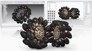
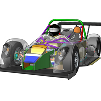
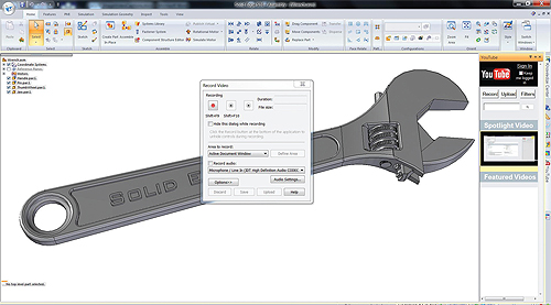
Photorealistic rendering. In the April issue of Design World, I wrote a feature on the growing importance of rendering to the product development process. ST7 now offers built-in rendering, courtesy of Luxion’s KeyShot technology, that enable users to quickly and easily create photorealistic images and animations from within the modeling environment, significantly improving the overall image quality and speeding real-time photorealistic rendering of native 3D models by up to five times, based on internal testing.

Solid Edge ST7 now includes built-in rendering courtesy of Luxion's KeyShot technology.
Solid Edge ST7 now include built-in rendering courtesy of Luxion’s KeyShot technology.

3D Sketching. This new functionality, which is available in the part, assembly and sheet metal environments, improves efficiency with various modeling scenarios, allowing designers to complete their design processes up to two times faster with greater flexibility. 3D Sketch can also be used to model pipes and wires that are bent in more than one plane, and in the assembly environment for the definition of exact paths for piping, wiring and tubing.

Improved UI. Enhanced user interface features a new start page, focused learning paths, and expanded visual tool tips that all simplify the learning curve for new users and increase efficiency for expert users. Startup page provides easier access to templates, recent documents, instructional videos, and the online community and standard parts.

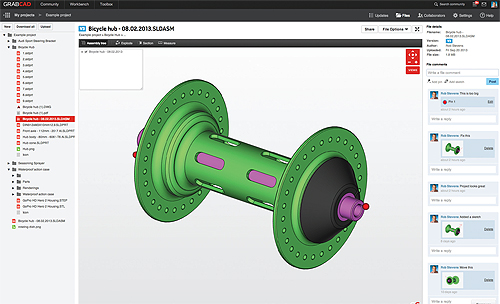
Visual data management. Design management capabilities, based on Microsoft’s SharePoint software, provide a more visual design management approach with a new workflow site that brings user interactions into one location. This makes it easier to create and work with complex design projects, complete engineering changes faster and improve overall productivity.

Faster assembly design. The Duplicate Component command speeds assembly design in which components are duplicated in many positions and orientations. Multiple copies of a component can be created based on designated “from” and “to” positions and orientations of existing components.

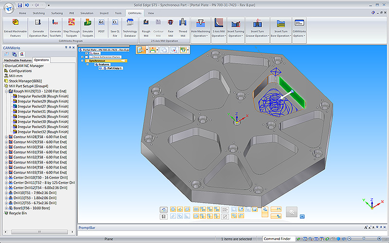
Create a blank from a 3D model. Rapid creation of manufacturing information for components that are manufactured using forming, stamping and deep drawn manufacturing processes is now possible using the “Create Blank” command that enables users to create a flattened blank for any 3D model.

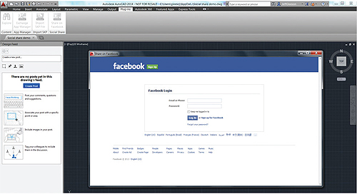
More apps. New Solid Edge apps provide wider capabilities for design, manufacturing and collaboration that speed the entire product development process. New apps include those that provide mobile access to standard and catalog parts; automated output of models for 3D printing; expanded manufacturing capabilities; and cloud-based collaboration. There are now over 500 Solid Edge apps available in the company’s app store.

We’re barely scratched the surface on all the enhancements packed into Solid Edge ST7, so check out this page on the Siemens PLM Software’s web site for more.

Filed Under: 3D CAD Package Tips, CAD Package, News, Siemens Blogs, Siemens PLM Tagged With: Solid Edge

Geometric Ships CAMWorks 2014 for Solid Edge

May 9, 2014 By Barb Schmitz Leave a Comment

Innovation is today’s CAD products is somewhat expected by users who constantly demand the next level of functionality. After all, designers and engineers are using modern CAD tools to design the next great product, or at least the next great version of a product. The same cannot necessarily be said on the CAM side, where progress to innovate tools has been slower.

As the costs of modern machining technology has dropped and become more accessible, more and more designers and engineers tasked with outsourcing prototyping or doing it in-house are getting more involved with the CAM side of the equation. They are also interfacing more frequently with the manufacturing personnel running CNC machines.

Crossing the CAD-CAM Divide

There’s traditionally been a bit of a divide between engineering and manufacturing, possibly a result of the fact that they “talk” different languages in that they use disparate systems. The format created by CAD programs doesn’t seamlessly transfer to the CAM program and engineers are often accused of “lobbing” models over to manufacturing for them to deal with.

To alleviate some of these issues, CAD-integrated CAM packages began to emerge. The goal was to create a CAD-like workflow for CAM so engineers and designers would not have to learn a whole new software system.

Yesterday, Geometric Ltd. announced the shipment of CAMWorks for Solid Edge users. The new version provides even tighter integration with Solid Edge, Siemens PLM Software’s 3D CAD software, to speed programming time and accelerate time-to-market.

CAMWorks is an embedded CAM program that is fully integrated with Solid Edge.

One of the software’s users, Tim Hoeing, a plant manager at H&M Tool & Die, is a big fan of the software’s feature-based approach. “The feature-based approach seems much more intuitive than the process of creating profiles and chains method,” says Hoeing. “The automatic feature recognition and tool path associativity helps reduce programming time by as much as ten times. And the knowledge-based machining will save machining strategies for future use, enabling faster turn-around times on new jobs.”

With this release, Solid Edge users will gain access to the full suite of CAMWorks modules, including Sync Manager and Sub Spindle operations manager to speed up CNC programming for complex multi-spindle, multi-turret mill turn machines.

In addition, with the 5-axis simultaneous machining module, users in the aerospace, medical device, and oil & gas industry have the ability to machine complex surfaces using advanced 4- and 5-axis machining centers. Furthermore, tool and die customers now have the ability to program the Wire EDM machines within the same environment as their milling operations instead of having to maintain different software for different purposes.

CAMWorks 2014 also adds new mill-turn capabilities along with 5-axis simultaneous machining and assembly-mode machining, enabling users to confidently and accurately create tool paths that avoid fixtures, clamps, and other necessary work-holding devices, which is essential for today’s complex machining centers.

For more on CAMWorks 2014, check out this page on the Geometric Ltd web site.

Barb Schmitz

Filed Under: CAM, News, Siemens Blogs, Siemens PLM Tagged With: cam, Siemens, Solid Edge

Debating the Most Efficient Way to Go from Concept to Documentation

April 15, 2014 By Barb Schmitz Leave a Comment

The conceptual phase of design is the only one within the product development window that must be inherently fluid, and in a sense, should be done in a leisurely manner. What, you ask? The word “leisure” is probably not used often when it comes to designing products, right? OK, let me explain.

In order to fully evaluate a suitable number of potential design concepts, engineers and designers must have the luxury of time. After all, how can you determine an optimum solution until you’ve discounted an adequate number of bogus ones? Unfortunately, not many of them get that time.

According to a conceptual design study conducted by PTC, 92% of respondents felt that their product development process would benefit tremendously from the ability to evaluate more concept ideas before moving forward into detailed design and documentation. Another 61% said that the concept design process is often cut short to due schedule constraints.

Time, after all, is critical to meeting design production schedules and shipping products on time. It’s the underlying reality of all those involved with product development.

This concept design for Yamaha was created by a Alberto Agnari. It included concept boards, sketches and traditional and digital renderings.

Which route to take: direct or feature-based?

Once a concept design has been approved and moved forward, time is of the essence. During our “The Pros and Cons of 3D Modeling Paradigms” webinar, one of the questions posed to our panel of speakers was in regards to what modeling paradigm is best in terms of time efficiency when moving from the concept stage to the documentation state, keeping in mind that a good percentage of the dimensions can be automatically generated within the history-based model. The answers were surprising and I thought worth sharing.

Dan Staples, vice president, Solid Edge Product Development, Siemens PLM Software

In a history-based system the dimensions are in the sketches and then those are retrieved into the drawing. In a direct modeling system, or at least in Solid Edge, the dimensions take the form of what we call PMI (product manufacturing information) or the 3D dimensions that are on the faces of the model instead of in the sketches. That doesn’t change the ability to retreat those into the drawing. The fact is that they’re on the faces instead of the sketches, same thing in terms of ability to retrieve those that are in the drawing and use them.

Brian Thompson, vice president of Creo Product Management, PTC

Yeah, I think if you have good workflows for creating or showing those dimensions in the 2D context, it could be similar in terms of efficiency to do either. I don’t see one modeling paradigm strongly standing out. There’s good efficient workflows for creating dimensions on models that have no underlying sketches, and there’s good workflows for showing them on models that do. As Dan and I have said, dimensions in the direct modeling environment can, in fact, still drive geometry if the user tells the system that’s what he wants.

You can still even get that behavior. Maybe not to the level you would get with a large feature-based, history-based parametric model, but you could still get that behavior. There may be some circumstances where one is slightly better than the other, but I’d say it’s fairly close in terms of efficiency to create that documentation. Would you agree Dan?

Dan Staples

I would actually say it’s somewhat more efficient. One of the constraints we forget about is that when you build up a history-based model, you build it up sketch by sketch by sketch. That’s not necessarily a natural way to dimension the part. In fact, it’s pretty bad practice in terms of a dimensioning scheme because you tend to have a lot more dimensional stack ups than you would like. Whereas if you’re in a direct modeler, you can put in dimension between two faces on the model that are far from each and there’s 50 features in between, and so you can actually have a much more natural dimensioning scheme that’s more immediately usable in the drawing when you see direct models in my opinion.

Brian Thompson

Yeah, I think we’ll agree there that bad modeling technique and your history-based parametric modeling will make it even harder in the drawing to do that. If you got a good, well-done history tree then maybe it’s not as hard but it’s a good point.

The bottom line

Though it’s not easy to sum up all the good points here, its clear the most time-efficient way to move your designs from concept to documentation is to use best practices when it comes to how you model your products and good dimensioning workflows. In other words, the use of good modeling techniques will always get you from Point A to Point B faster, whether you’re working in a direct modeling or feature-based modeling 3D CAD system.

If you missed the “Pros and Cons of 3D Modeling Paradigms” webinar, you can watch it in its entirety here.

Barb Schmitz

Filed Under: 3D CAD Package Tips, Creo, Siemens PLM Tagged With: concept design, Creo, documentation, Solid Edge

The Challenges of Model Editing in the Multi-CAD World

February 27, 2014 By Barb Schmitz Leave a Comment

In today’s world, most engineers and designers are now accustomed to dealing with CAD data created in other CAD systems. With design collaboration with suppliers, partners, and customers being a key component of today’s product design, the use of multiple CAD systems has become the norm.

As a result, companies must become proficient at working with CAD data in multiple formats in order to succeed. Not only must they be able to send and receive data in multiple CAD formats, but also they must be able to quickly get to work on that CAD data without having to rebuild models from scratch or waste too much time fixing data to get clean geometry.

On average, companies use 2.7 different CAD systems internally. Here’s another daunting statistic: nearly half (49%) of companies struggle with importing models created in other CAD tools into their 3D CAD system, and another 59% say modifying imported models from other CAD tools is difficult using their CAD software.

Vital design cycle time is wasted when models must be recreated; yet making changes to those models is also problematic as intelligent features and patterns built in by feature-based CAD authoring systems are often lost once imported into another CAD system. So what is a company to do when navigating through multi-CAD environments?

Nearly half of all product development companies continue to struggle with how best deal with CAD data originating in other CAD systems. Image courtesy of Siemens PLM.

During the Q&A portion of a recent webinar, “The Pros and Cons of 3D Modeling Paradigms,” a question was posed to the speakers as to how best to approach making changes to CAD models that were created in a different CAD system. I think the responses are worth sharing as it’s something with which half of all companies continue to struggle.

Brian Thompson, vice president of Creo Product Management at PTC
“It’s pretty obvious that data inoperability between CAD systems has been tried at the feature level, and it’s generally not all that successful, at least not in a robust way. In general, when you take data in from another CAD system, you’re going to get information like assembly structure but for the geometry, you’re going to get just a closed volume, assuming that the data translation for the solid or the geometry came across well. Unless you want to just use your own history-based features to cut geometry out and recreate it from scratch, direct modeling tools are an ideal set of tools to manipulate geometry that’s come in from a CAD system in which you don’t have the features any longer.

It’s a pretty nice approach to be able to move faces, to align faces, to resize analytic geometry, to symmetrically change a model if it looks like it might be symmetric. There’s lots of tools built into most direct modeling environments that will give you great control over geometry regardless of the fact that that geometry had no features when it came over. You can actually use direct modeling tools to really control that geometry in pretty sophisticated ways despite the fact that when you got it, you didn’t get any features at all.”

Dan Staples, vice president of Solid Edge Product Development, Siemens PLM.

“I would just add that I don’t think it is, to be honest, any contest. If you were to be reading data from another system and you could choose to read it into the history-based environment and non-history-based environment, definitely read it into the non-history-based environment. You have much more flexibility and ability to make the changes you want to make.

I would suggest that in fact if you’re a diehard history-based user, but your system supports a non-history sort of mode, that this is where you want to try it. Certainly we’ve seen our users who when they want to get started with, in our case, synchronous technology and they are asking themselves ‘do I want to use it or do I not want to use it?’ Well, by gosh, the first place to use it (direct modeling) is with that imported data, it’s definitely a homerun there.”

Chad Jackson, principal analyst at Lifecycle Insights and a speaker at the webinar, authored a whitepaper that addresses the challenges of working in multi-CAD environments. You can read “Multi-CAD Data, Unified Design” here. To listen to the entire “The Pros and Cons of 3D Modeling Paradigms” webinar, click on this link.

Barb Schmitz

Filed Under: Creo, News, Siemens PLM Tagged With: cad, Creo, PTC, Solid Edge

Behavioral Changes Needed to Switch from History-based to Direct Modeling

February 21, 2014 By Barb Schmitz Leave a Comment

Participants in yesterday’s “The Pros and Cons of History-based and Direct Modeling Paradigms” webinar heard from three leading experts on the strengths and weaknesses of both modeling approaches as well as where each modeling approach shines throughout the product development process. We learned that both tools are useful though some are better suited for particular applications as well as for use in specific phases of the product development process.

CAD-Webinar-image

While I won’t even attempt to summarize the hour+ webinar, one of the questions during the Q&A at the end revealed some interesting insights on behavioral changes needed by users to effectively switch from the more traditional history-based 3D modeling techniques to direct modeling. Here are some of the responses to this question from our panelists:

Chad Jackson, principal analyst for Lifecycle Insights

“The one change in behavior that has to happen is with history-based approaches, people have to be so careful in how they build up their model so that it can be reused that it can take longer than really required. Or you have people who don’t care and build these really unstable models. Direct modeling tools can make for lazier modeling, and I mean that in a good way. You don’t get paid to build the perfect feature-based 3D model, you get paid to create a great design, document it and pass it on. In that regard, direct modeling can support that approach.”

Dan Staples, vice president, Solid Edge Product Development, Siemens PLM Software

“I think that you need to be open. We often see is that people are either successful or fail at adopting direct modeling tools based on the openness of their mind. If they are so tied into history-based modeling that they can’t open their mind, they are typically not successful. Whereas those that say, ‘This looks interesting. I’m going to try it and going to fail–at least for the first week because it’s so different—-but I’m going to persist.’ You also have to be willing to change your thought process, which is uncomfortable.

For example, when you create a sketch and its extruded and the faces are all there, you really don’t need the sketch anymore but it’s hard to let go of it. It’s kind of like when you first learn to ice skate, you don’t want to let go. Sooner or later, you can let go, because you don’t need the sketch to make changes.”

Brian Thompson, vice president of Creo Product Management, PTC.

“If you’re at a company that has traditionally built its products using a history-based approach, it’s useful to think about adopting direct modeling from the standpoint of a couple of key use cases, certain types of parts that you’ve had trouble with the history-based models. Build the motivation around a business case that you have the opportunity to improve, whether it’s concept design, detailed design, simplication for simulation. So go about learning that new tool with the motivation to be diligent to stick with it. Tell your management that we have the opportunity to improve our efficiencies in concept design, or designing certain parts, or simplifying models for simulation. Learn the tool with the motivation to improve those processes.”

You can watch the entire “The Pros and Cons or History-based and Direct Modeling Paradigms” webinar here.

Barb Schmitz

Filed Under: News, PTC News, Siemens PLM & Events Tagged With: 3D modeling, PTC, Siemens, Solid Edge

CAD Goes Social

January 15, 2014 By 3DCAD Editor Leave a Comment

Are engineering software developers pushing the collaboration envelope so that distributed users can edit complex 3D models at the same time?

Ever since the advent of the Internet and the World Wide Web, many CAD/CAE/CAM companies have been trying to leverage online technologies so users in distributed environments can “get more social” to improve their designs. For example, years ago, CAD software already featured tools such as embedded chat that let users communicate with each other remotely one-on-one or in small groups. Currently, many packages include hooks to social media tools such as YouTube videos and online forums. In fact, individuals in all areas of CAD are engaging with each other like never before and it is social utilities on the Web making this possible.

But what about pushing the social collaboration envelope by giving remote users the capability to edit complex 3D models online at the same time? This idea actually arose as early as the mid-1990s with the former CoCreate, which ran its CAD software on a server, developing a system that let team members control the cursor and thereby work concurrently.

Nanosoft’s Evan Yares said, “Previous collaboration features were technically interesting, but they failed to impact the market. However, improved standards along with other more advanced enterprise applications might now make the concept more realistic. In fact, current research at Brigham Young University uses existing high-end CAD packages and ties them together with a ‘game engine’ framework. Students work together as if in a multiplayer game to edit 3D models while wearing headsets that let them talk together as they work. The researchers claim that such simultaneous group access leads to significant productivity improvements.”

To understand the concept better, consider the simple analogy of editing a document in Google Docs, a cloud-based application that lets enabled users simultaneously open and edit a document from anywhere. The approach works well as long as measures are in place to prevent users’ edits from “colliding.” But editing a CAD model poses more challenges because models are often built using a recipe of uniquely related and ordered features. Any change in a defining parameter by an uninformed user could cause the model to crash.

This all begs the question: Has the rise of more advanced technology caused major developers to create tools to support the concurrent editing of complex 3D models?

Asynchronous collaboration on the forefront
“As described, concurrent collaboration is cutting edge because most engineers don’t see the value of editing a 3D CAD model simultaneously with other users,” said Rob Stevens, VP of Sales and Marketing, of the online site GrabCAD. “Our service is mostly asynchronous.”

Basically, GrabCAD lets users upload and download free CAD models—not exactly a new concept—but the company has a slightly different take. Say a bike frame manufacturer is designing a frame and wants to put wheels on it. Although the company doesn’t make or sell wheels, it spends the time to design the wheels anyway just to be able to showcase the model. In GrabCAD’s approach, because users have already uploaded models of bike wheels, the bike manufacturer merely needs to find an appropriate model to put wheels on its bike.

“From the collaboration angle, our users are professional engineers who want to share their designs with a small group and work together on a project,” said Stevens. So that everyone in the world can’t see the work, we launched Workbench, a private visualization tool for CAD.”

The tool lets designers start a project online and drag files like a CAD model, image, and movie into a project. Designers type in the email addresses of those they want to share the design with, providing a link to the design. Clicking on the link lets group members see the model displayed on their Web browser. They can spin, rotate, section, and measure the model, and even sketch on it. And with the recent integration of GrabCAD with Autodesk’s cloud-based AutoCAD 360 and Fusion 360, the members of the GrabCAD community can now edit their models in 2D and 3D, both in the public Library models and private Workbench models.

autodesk-social-share
The Autodesk Social Share plug-in lets users share their drawings in Facebook.

The site makes for a productivity improvement over how many engineers today collaborate, said Stevens. “For instance, designers might take screenshots, paste them on a PowerPoint and email them to the team. The ensuing feedback helps the designer reinterpret the model. This approach is inefficient and time consuming.”

“GrabCAD is almost like a Facebook because it includes a stream of comments about a design. Users can leave for a day, come back, login and see that ‘Bob’ uploaded a new version of a design, ‘Sarah’ didn’t like the color, and ‘Henry’ says it’s too expensive to manufacture. All this is happening in a secure location.”

grabcad
GrabCAD is similar to Facebook in that it includes a stream of comments about a design.

According to Stevens, the company provides some synchronous tools that let users see who is online, but users are more interested in asynchronous features.

“That’s because it’s rare for everyone to be online at the same time,” he said. “What companies are really worried about is how to move projects forward faster by avoiding the lengthy delay of getting busy engineers to take screenshots.”

Stevens believes the idea of real-time gamification is probably two steps ahead of industry. “Traditionally, engineering has been very closed,” he said. “Twenty years ago, mechanical engineers just sat at their desks and created designs. Engineers attended big design review meetings where everyone shouted out comments, then went back to their desks. It was solitary work. That is starting to change, with engineers using online communities and crowdsourcing for ideas and talent. But getting designers to share their CAD model with anybody at all is in itself a big a step. The next phase might be doing this in real time, which probably has a relatively narrow application right now.”

Getting designs to market quickly
CAD going social in the sense of real-time design and collaboration is an interesting topic because it narrows down the idea of ‘social media,’ which most engineers think of as fluffy,” said SVP and General Manager of Mainstream Engineering at Siemens, Karsten Newbury. “Most CAD companies try to build software that addresses engineers’ challenges. This dictates the approach companies take in developing tools.”

According to Newbury, in looking at collaborative design, the biggest challenge engineers face is to get their job done. “Most designs today involve multiple parties across the supply chain or multiple entities within the company, so working together on a design productively and efficiently is critical,” he said. “We think the right direction is probably a mix of the asynchronous and concurrent approaches.”

Collaboration in most companies is driven by the need to get designs to market ever more quickly, said Newbury. “The capability to react quickly is important mostly because of the rise of mass customization,” he said. “Customers want their own personal flavor of a standard product. The more a company can meet that demand, the bigger the competitive edge it will have.”

A significant challenge to collaboration is model reuse. “When companies want to change designs quickly, they need to have the capability to reuse designs, not reinvent them from scratch,” said Newbury. “Unfortunately, engineers must often recreate designs from scratch because it’s hard to understand the design intent of someone else’s initial model. Technologies such as our Synchronous Technology (an advanced form of direct modeling) in Solid Edge make it easier to reuse existing data in different designs by letting users create designs without worrying about the history tree. Multiple individuals, therefore, can make changes and don’t have to fear that the model will crash. Whether the approach is offline and iterative or more and more real time, changing data independent of its source without breaking the model is paramount in supporting efficient collaboration.”

To help address these challenges, Solid Edge also integrates with GrabCAD, a secure community, which offers an offline-online combination that makes a lot of sense, said Newbury. “Of course the word ‘secure’ is important here. Should a company expose a design to an open community, the company would obviously risk having its intellectual property stolen.”

solid-edge-sp
Solid Edge SP, Solid Edge for SharePoint, includes visual tools to help engineers manage complex design data better. A graphical view of an assembly, with thumbnails for each component, lets users easily navigate the product structure. Having the capability to quickly see what components are in an assembly can help companies collaborate faster and reduce design times.

Also, collaborative design benefits from in-context learning. “In the typical sense of CAD going social, Solid Edge now includes built-in YouTube functionality. Designers can use Solid Edge as a YouTube recorder to share a design problem with another user, or as a search engine to find a video that addresses a problem,” said Newbury. “And we just started an online community, which is monitored by experts, where users can post questions and get answers in real time.”

For synchronization in a multi-user environment, although the technology today doesn’t support concurrent collaboration, a SolidEdge plug-in leverages Microsoft SharePoint (of course, other software does this as well). “The tool leverages SharePoint as its ‘source of truth’ so an updated model ‘knows’ when a change has been made. This allows for data integrity, up-to-date models and effective collaboration. The real question is how concurrent collaboration really needs to be to maximize productivity while avoiding design conflicts,” said Newbury.

solid-edge-sp-2
It is common for designers to receive 3D models in various formats. Because model intelligence is lost during any translation, designers have few options with repurposing foreign data. Here, synchronous technology within Solid Edge lets users select and move geometry (the hole shown in blue) into a new shape, and Live Rules finds and maintains key geometric conditions. With this capability, users can better collaborate and reuse imported models from many different systems.

Addressing the problem of different workflows
According to Rob Maguire, senior product manager of AutoCAD, “The social angle is one piece of collaborative design. For example, our AutoCAD 360 software supports the simultaneous editing of DWG files in an online, browser-based context.”

Autodesk and some of its customers do use gaming engines, not for real-time editing, but for visualization, said Maguire. “For example, in the design of the new Dallas Cowboys Stadium, the architects used a gaming engine to load in AutoCAD and 3D Studio Max models that let them visualize the line of sight to the field from every seat in the house,” he said. “Abstracting this approach could lead to concurrent editing.”

Another AutoCAD feature called Design Feed allows users to associate comments with specific points or areas inside a given drawing. For instance, say the drawing is of a set of stairs. A user can take a picture of the physical stairs and associate it with the AutoCAD drawing by adding the photo to a comment in the Design Feed. Comments about the design are sent through an email feature and are spatially located in the drawing to help users resolve problems and add context.

“However, concurrency based workflows raise a lot of questions when it applies to complex 3D models,” said Maguire. “For example, CAD users expect data integrity and must have a high confidence that all of their changes are pristine. Because of potential editing conflicts, a more sophisticated sort of transactional model is needed—such as a product data management (PDM) system—than currently provided. Without PDM in place to manage the 3D data, a human is needed to make a judgment call and pull everything together, which can lead to mistakes in large assembly environments. The trick is developing a program that provides high data confidence in an easy to use, accessible way.”

It is difficult to generalize the process of concurrent editing because each workflow is a little bit different, said Maguire. “For example, say a group is collaborating on designing new restaurants for a popular fast food chain. Because the chain restaurants are almost all alike, with similar roofs, signs and the like, they are a configurator type of design. Contrast that to the design for a car engine. When a hundred people are working on the design, the tolerance for error is much less and the need for collaboration is much higher. What happens when a manufacturing engineer changes a feature and a performance designer changes the feature to something else at the same time? Creating software that can resolve these kinds of conflicts is a large task but perhaps might become possible in limited cases for specific industries and workflows.”

Reprint info >>

Autodesk
www.autodesk.com

GrabCAD
www.grabcad.com

Solid Edge
www.plm.automation.siemens.com

Filed Under: 3D CAD Package Tips, Autodesk News, CAD Industry News, Siemens PLM & Events Tagged With: Autodesk, GrabCAD, Solid Edge

The failed promise of parametric CAD, final chapter: A viable solution

November 18, 2013 By Evan Yares 5 Comments

Model reuse
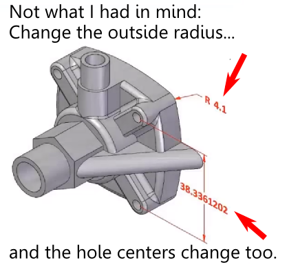
What is the failed promise of parametric CAD? In short, model reuse.

It’s a lot more difficult than it ought to be, for a variety of reasons. Several months back, I wrote a series of articles discussing those reasons, as well as some of the solutions that have come up over the years.  What was missing from the series was a final chapter; a detailed description of what could prove to be a viable solution to problems with model reuse: the resilient modeling strategy.

The resilient modeling strategy (RMS) is the brainchild of Richard “Dick” Gebhard. I wrote about Dick last June, in the article A Resilient Modeling Strategy. He’s a low-key guy with deep experience and serious expertise in the practical use of MCAD software. Over his career in CAD, he’s been a reseller for CADKEY, Pro/E, and most recently, Solid Edge.

RMS is a best practice for creating CAD models that are stable and easily reusable (even by inexperienced users.)  It can be learned and easily used by typical CAD users, it preserves design intent in models, and provides a mechanism by which managers or checkers can quickly validate a model’s quality.

Resilient Modeling Strategy

When Dick first started thinking about the concepts that make up the resilient modeling strategy, it was natural that it was in the context of showing the advantages of Synchronous Technology (The Siemens PLM brand name for its version of direct modeling.) In our discussions about RMS over the last year or so, I pointed out that, while I thought that RMS did indeed demonstrate the benefits of hybrid history/direct modeling in Solid Edge, for it to be taken seriously, and not be unfairly dismissed as a marketing initiative for Solid Edge, it needed to work with a wide variety of MCAD tools. I think Dick got where I was coming from, because he’s continued to refine and generalize RMS, with feedback from users of a number of MCAD systems.

In its current incarnation, RMS works particularly well with Solid Edge, as might be expected, but also works very well with Creo, NX, CATIA, and IronCAD (all of which are hybrid history/direct systems.) Further, with a few modifications, it can provide compelling value with SolidWorks, Inventor, and Pro/E (all of which are primarily history-oriented systems.)

It’s significant that RMS is also free to use. While Dick is available to provide presentations, seminars, and training, he has not attempted to patent, or keep as trade secrets, the underlying concepts of RMS. (He does claim a trademark on the term “Resilient Modeling Strategy,” which means that organizations offering commercial training on RMS will need to get Dick’s OK to use the term.)

Dick has posted an introductory presentation on RMS at resilientmodeling.com. While the entire presentation is 20 minutes long, the first 3-1/2 minutes cover the problems that people invariably experience when reusing or editing history-based CAD models. Watching that much will likely convince you to watch the rest.

On Wednesday, November 20, at 10:00 AM PST, Dick will be hosting a webinar on RMS. It’s scheduled to last just 30 minutes, with the emphasis on content, not hype. If you’re a serious CAD user or a CAD manager (or, for that matter, you work for an MCAD developer), it’ll be well worth your time to attend.

TL;DR: Resilient Modeling Strategy is a best practice for creating high quality reusable 3D MCAD models. It works with many CAD systems, it’s easy to learn and use, and it’s free. Big payoff for MCAD users. 

Presentation at resilientmodeling.com

Register for Nov 20 webinar on Resilient Modeling


Filed Under: Catia, Creo, Evan Yares, Featured, Inventor, News, Pro/Engineer, Siemens PLM, SolidWorks Tagged With: 3D CAD, Catia, Dassault Systemes, Evan Yares, Inventor, IronCAD, PTC, Siemens PLM, Solid Edge, SolidWorks

The failed promise of parametric CAD part 5: A resilient modeling strategy

June 25, 2013 By Evan Yares 3 Comments

bamboo-garden
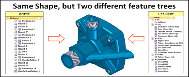
The model brittleness problem inherent with parametric feature-based modeling is a really big deal. And it’s something, honestly, that I don’t have a great answer for. I’ve even asked a few power users who I know, and their answers seemed to involve a bit of hand-waving, and a reference to having lots of experience.

While best practices are a potentially good step forward, they need to be straightforward enough that mere mortals (as opposed to power users) can follow them.

Around Christmas last year, I got a call from Richard Gebhard, an engineer’s engineer, who has made his living selling CAD, and training people to use it (including more than his fair share of power users), for longer than he would like me to admit. (I’m pretty sure I’ve been in the CAD industry longer than him, though.) Richard told me he had something he wanted to show me, and if I’d take the time to meet him, he’d buy me lunch.

What Richard showed me was a way of creating and structuring CAD models that made a lot of sense. It not only reduced parent-child dependencies, but it made them more predictable. And, more importantly, it made it a lot easier for a mere mortals to scan through the feature tree, and see if there were any grues (it’s a technical term. Feel free to look it up.)

Over the next several months, we had lunch several times. I made suggestions. He rejected some, accepted some, and thought about others. At the same time, he was bouncing his ideas off several of his best power users (including his son). By a couple of months ago, he had refined his system to the place where it would work impressively well with nearly any parametric feature-based CAD system. So, he went to work finalizing his presentation.

I had mentioned that Delphi, by patenting some of the elements of horizontal modeling, limited the number of people who could benefit from it. (Worse for them, they patented it, then filed bankruptcy. That didn’t help much.) Richard’s goal wasn’t to monetize his process. His goal was to evangelize it. To help CAD users—both power users and mere mortals—to get their jobs done better.

Richard and I had talked, over time, about what he should call this process. At first, I liked the word “robust.” In computer science, it is the ability of a system to cope with errors during execution. In economics, it is the ability of a model to remain valid under different assumptions, parameters and initial conditions. Those are good connotations. But, then I thought of one of my favorite examples of robustness. The first time I visited Russia, I noticed that the apartment buildings were built of thick poured concrete. Very robust. And nearly impossible to remodel.

Richard’s system wasn’t robust. It was resilient. So, he has named it the Resilient Modeling Strategy. RMS.

So far, I’ve written over 2,600 words, to provide some background on the problems of parametric modeling, and some of the solutions that have been offered over the years. But, after all that, I’m not going to tell you anything more about RMS. At least, not yet.

Tomorrow, Wednesday, June 26, Richard will present RMS for the first time ever, at Solid Edge University, in Cincinnati, Ohio. His presentation will start at 9:00AM local time, and will be in room 6 of the convention center. If you’re there, put it on your calendar. If not, you’ll need to wait until Richard gets back to Phoenix, and I publish a follow-up post.

RMS is not anything difficult, or fundamentally new. It’s just an elegant distillation of best practices, designed to work with nearly any parametric CAD system, and simple enough that it doesn’t get in the way.  It’ll help you make better CAD models faster.

Filed Under: Alibre, Autodesk, Creo, Design World, Evan Yares, Featured, Inventor, Pro/Engineer, Siemens PLM, SolidWorks Tagged With: Creo, Inventor, IronCAD, Solid Edge, SolidWorks

The failed promise of parametric CAD part 4: Going horizontal

June 25, 2013 By Evan Yares 12 Comments

In the early 90s, Ron Andrews, a senior product designer at Dephi’s Saginaw Steering Systems Division, became fed-up with the difficulties of editing parametric CAD models. So, he and a team of his colleagues, including Pravin Khurana, Kevin Marseilles, and Diane Landers, took on a challenge of trying to find a solution.

They came up with an interesting concept that they called horizontal modeling. Here’s a description of it from their patent abstract:

“Disclosed is a horizontal structure method of CAD/CAM manufacturing where a base feature is provided and one or more form features added to it to form a model. The form features are added in an associative relationship with the base feature, preferable a parent child relationship, but are added in a way as to have substantially no associative relationships with each other. The result is a horizontally-structured Master Process Model where any one form feature can be altered or deleted without affecting the rest of the model. Extracts are then made of the Master Process Model to show the construction of the model feature by feature over time. These extracts are then used to generate manufacturing instructions that are used to machine a real-world part from a blank shaped like the base feature.”

Here’s a picture that makes it clearer:

Horizontal Modeling

The simplest explanation I can give for it is this: You create a base feature, and bunch of datum (working) planes. You attach all the child features to those datum planes. Viola: no parent-child problems.

I admit that I’m not going to do justice to horizontal modeling in this conversation. There’s actually quite a bit to it, and it makes a lot of sense when coupled with computer-aided process planning (CAPP.)

Horizontal modeling has a handful of problems. First, it does a pretty good job of killing the possibility of having design intent expressed in the feature tree. Next, it works better with some CAD systems than others. (When horizontal modeling was in the news, SolidWorks had a problem managing the normals on datum planes, so it didn’t work too well.) The deadliest problem is that Delphi got a bunch of patents on the process, then licensed it to some training companies. From what I can see (and I may be wrong), none of these training centers offer horizontal modeling classes any more.

While, technically, you can’t use horizontal modeling without a patent license from Delphi, the concepts at its core are fairly similar to things that CAD users have been doing for years. A few years ago, Josh Mings posted on a couple of online forums that “Horizontal Modeling is just one word for it, you may also know it as Skeleton Modeling, Tier modeling, Sketch Assembly modeling, CAD
Neutral Modeling, or Body Modeling.” (It’s actually two words for it, but I get his point.)

Horizontal modeling is not a silver bullet solution for the problems inherent in parametric feature-based CAD. It’s just a best practice—a strategy for getting around the problems. It seems to be headed in the right direction, but it suffers from the complexity that comes from trying to fix too many problems at once.

Next: A Resilient Modeling Strategy

Filed Under: Alibre, Autodesk, Creo, Design World, Evan Yares, Featured, Inventor, Pro/Engineer, Siemens PLM, SolidWorks Tagged With: Creo, Inventor, IronCAD, Solid Edge, SolidWorks

The failed promise of parametric CAD part 3: The direct solution

June 25, 2013 By Evan Yares 5 Comments

Pull-PushDirect modeling—a syncretic melding of concepts pioneered by CoCreate, Trispectives, Kubotek (and many others)–has shown the most promise to cure the parametric curse.

Direct modeling is today’s hot CAD technology. PTC, Autodesk, Siemens PLM, Dassault (CATIA, but not so much SolidWorks), IronCAD, Kubotek, Bricsys, SpaceClaim (and certainly some other companies I’ve forgotten) all have their own unique implementations of it.

The common thread in direct modeling is to use standard construction techniques when modeling, and feature inferencing (or recognition) when editing. It’s easier said than done. It’s taken about 35 years of industry research to get to the place we are today—where you can click on a face of a model, and the system will recognize that you’re pointing to a feature that has some semantic value. And that’s not even considering the tremendous amount of work that has been required by legions of PhD mathematicians to develop the math that lets you push or pull on a model face, and have the system actually edit the geometry it in a useful manner.

For the CAD software, figuring out which way to edit a selection is almost a mind reading trick: A user clicks and drags on a part of a model. What would they like to happen? In some cases it’s easy: Drag once face of a rectangular block, and the system will just make it longer or shorter. But if the block is full of holes, bosses, and blends, it becomes a lot more complicated. What should the system do if you drag a face so far back that it consumes another feature, and then pull it back to where it was? Should the consumed feature be lost forever, or should the system remember it in some way, so it can be restored?

There are no right answers. It seems that no two direct modeling systems handle the decision of what is a “sensible” edit in the same way.

While direct modeling absolutely solves the model brittleness problem inherent with parametrics, it does it by simply not using parametrics. Even with hybrid parametric/direct CAD systems, the answer to the parametric curse is still to not use parametrics when you don’t need to.

The solution of “use direct modeling when you can, and learn to live with parametric hassles when you can’t” just isn’t very satisfying to me.

Next: Going horizontal

Filed Under: Alibre, Autodesk, Creo, Design World, Evan Yares, Featured, Inventor, Pro/Engineer, Siemens PLM, SolidWorks Tagged With: Creo, Inventor, IronCAD, Solid Edge, SolidWorks

  • Go to page 1
  • Go to page 2
  • Go to Next Page »

Primary Sidebar

3D CAD NEWSLETTERS

MakePartsFast

Footer

3D CAD World logo

DESIGN WORLD NETWORK

Design World Online
The Robot Report
Coupling Tips
Motion Control Tips
Linear Motion Tips
Bearing Tips

3D CAD WORLD

  • Subscribe to our newsletter
  • Advertise with us
  • Contact us
Follow us on Twitter Add us on Facebook Add us on LinkedIn Add us on Instagram Add us on YouTube

3D CAD World - Copyright © 2022 · WTWH Media LLC and its licensors. All rights reserved.
The material on this site may not be reproduced, distributed, transmitted, cached or otherwise used, except with the prior written permission of WTWH Media.

Privacy Policy