CAD-integrated CAM software greatly facilitates the communication between design and manufacturing by removing the error-prone process of having to translate data between two systems. It also helps decrease the traditional disconnect that exists between the two groups of users, enabling both teams to do the work concurrently.
Delcam recently launched Delcam for SolidWorks integrated CAD system, which includes a range of new features for three-axis milling, drilling, turning and wire EDM.
Programming of three-axis toolpaths for complex parts has been made easier and more reliable in Delcam for SOLIDWORKS 2015 with the addition of automatic collision checking of the tool shank and holder, as well as the cutter, for both roughing and finishing operations. If a gouge is detected the toolpath can be recalculated with any segments that will cause a gouge clipped away.
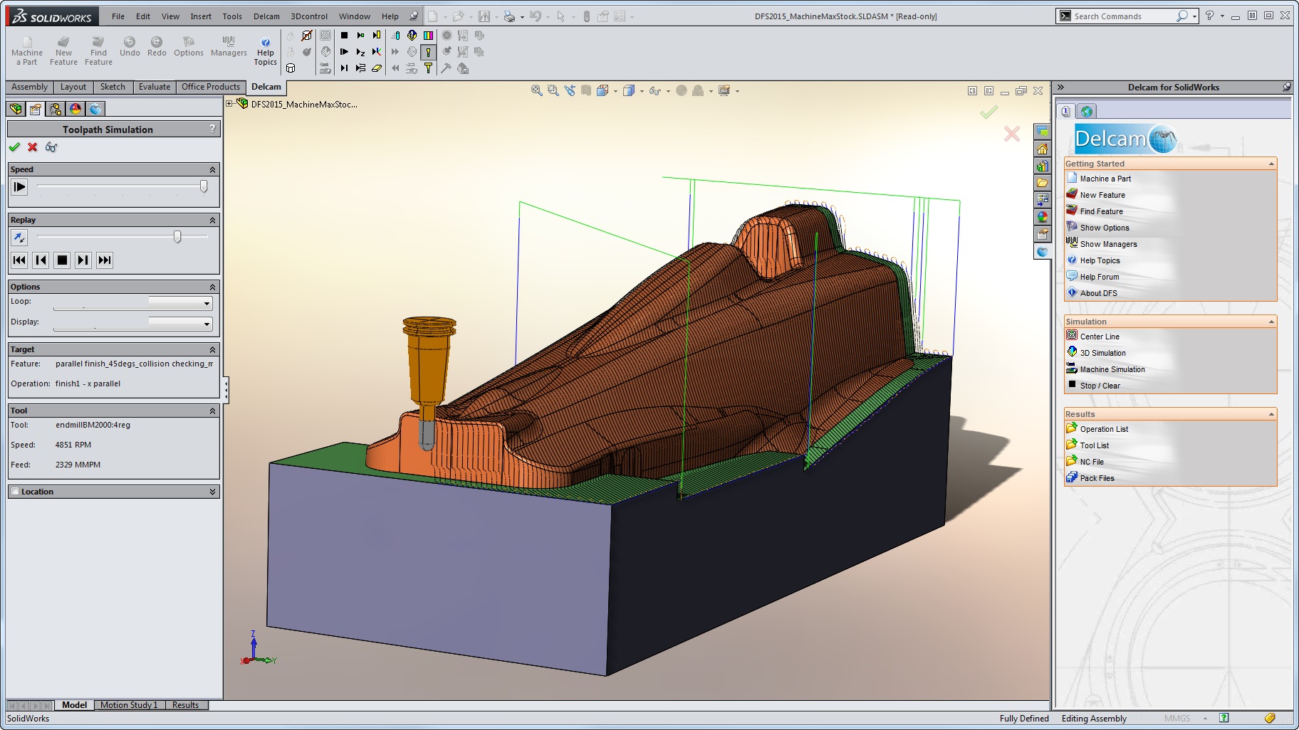
Removing these segments of the toolpath leaves an area of unmachined stock that will need to be removed with a longer tool. This extra toolpath is able to be calculated using a stock model of material remaining after the shorter tool has been used to ensure there is no re-machining of stock that has already been removed.
As part of this development, an additional function, called ‘maximum machine stock’, has been added that removes direct moves where clipping has occurred. These direct moves can leave witness marks on the part so their removal should improve surface finish.
Another improvement in three-axis machining with Delcam for SOLIDWORKS 2015 allows stock models to be used in conjunction with other geometry, such as the part surface dimensions, solid models, the stock dimensions and boundary curves. This addition gives better control over the area to be machined by each toolpath and so gives more efficient machining by allowing the user to confine toolpaths to specific regions and to eliminate air-cutting by referencing the stock model.
Three-axis flowline and isoline machining is now more flexible, with users able to choose to move the tool in an in-to-out direction or an out-to-in direction.
Drilling with Delcam for SOLIDWORKS has been made easier in the new release with the introduction of a new hole type, ‘Thread Mill Hole’, which eliminates the need to create holes, pockets or sides, and thread features as separate items. It can be used either with holes created with the ‘Hole’ feature or those that have been identified with ‘Feature Recognition’.
Another improvement to drilling is the new ‘Find Feature’ command that gives the ability to combine similar holes into groups on indexed parts. With previous releases, users had to have a separate feature for each hole but, in Delcam for SOLIDWORKS 2015, holes that are similar can be recognized and then grouped together. This makes them much easier to manage and edit.
A series of improvements have been introduced to make turning with Delcam for SOLIDWORKS more efficient. The software is now able to produce toolpaths that rapid up and over previously machined diameters, rather than feeding along them. This reduces the overall cycle time and avoids dragging of the tool.
For users of wire EDM, Delcam for SOLIDWORKS 2015 provides an expanded wire-cut database to support multiple machines having varying formats and methods of operation, with the ability to specify nozzle type and fluid type as well as material type and thickness, wire type and diameter, and EDM machine. This gives more flexibility by providing the option to store and apply a greater variety of different parameters.
Wire EDM assemblies with multiple setups are now able to be output in a single program separated by Program Stops, with NC code required for a safe Program Stop formatted in a special section of the post processor. This increases programming flexibility greatly for Wire EDM users, allowing them to manage their parts on the machine more safely.
A key benefit of Delcam for SOLIDWORKS has always been the availability of a wide range of post-processors, together with the ability for users to customize their posts. In the 2015 version, post variables are able to be assigned user-defined names. This allows users to see quickly exactly which post variables are configured for use with a particular post-processor and to understand their intended use. This change is particularly valuable when programmers need to understand customizations in posts that have been made by other users.
Delcam for SOLIDWORKS combines the benefits associated with Delcam’s PowerMILL and FeatureCAM CAM systems. It is based on Delcam’s proven machining algorithms that are already used by more than 45,000 customers around the world. The software offers PowerMILL’s exceptional speed of toolpath calculation, plus the advanced strategies for high-speed and five-axis machining, to ensure increased productivity, maximum tool life and immaculate surface finish, even when cutting the hardest, most challenging materials. At the same time, Delcam for SOLIDWORKS has the same strong focus on ease of use as FeatureCAM, including all of the knowledge-based automation that makes that system so consistent and reliable.
Delcam for SOLIDWORKS is fully integrated into the SOLIDWORKS environment so that the program looks and behaves like SOLIDWORKS. It offers full associativity so that any changes in the CAD model are reflected automatically in the toolpaths. However, this associativity is more intelligent than that offered in many other integrated CAM systems. Delcam for SOLIDWORKS doesn’t simply modify the existing toolpaths but also reviews the choice of cutting tools and machining strategies, and changes them if necessary.