
The modern era of 3D CAD was born in September 1987, when Deere & Company bought the first two seats of Pro/Engineer, from the still new Parametric Technology Corporation. A couple of years later, Deere’s Jack Wiley was quoted in the Anderson Report, saying:
“Pro/ENGINEER is the best example I have seen to date of how solid modelers ought to work. The strength of the product is its mechanical features coupled with dimensional adjustability. The benefit of this combination is a much friendlier user interface plus an intelligent geometric database.”
According to Sam Geisberg, the founder of PTC:
“The goal is to create a system that would be flexible enough to encourage the engineer to easily consider a variety of designs. And the cost of making design changes ought to be as close to zero as possible. In addition, the traditional CAD/CAM software of the time unrealistically restricted low-cost changes to only the very front end of the design-engineering process.”
To say Pro/E was a success would be a terrible understatement. Within a few years PTC was winning major accounts from the old-line competitors. In 1992, on the strength of its product, PTC walked away with a 2,000 seat order from Caterpillar that Unigraphics had thought was in the bag.
The secret to Pro/E’s success was its parametric feature-based solid modeling approach to building 3D models. To companies such as Deere and Caterpillar, it offered a compelling vision. Imagine being able to build a virtual CAD model of an engine, and, by changing a few parameters, being able to alter its displacement, or even its number of cylinders. And even if that wasn’t achievable, it would be a great leap forward to just be able to rapidly create and explore design alternatives for parts and assemblies.
Yet, things were not that easy. In 1990, Steve Wolfe, one of the CAD industry’s most insightful observers, pointed out that Pro/E was incapable of making some seemingly simple parametric changes.
David Weisberg, editor of the Engineering Automation Report (and from whose book, The Engineering Design Revolution, I have liberally cribbed for this article), pointed out the fundamental problem with parametrics:
“The problem with a pure parametric design technique that is based upon regenerating the model from its history tree is that, as geometry is added, it is dependent upon geometry created earlier. This methodology has been described as a parent/child relationship, except that it can be many levels deep. If a parent level element is deleted or changed in certain ways it can have unexpected effects on child-level elements. In extreme cases (and sometimes in cases that were not particularly that extreme), the user was forced to totally recreate the model… Some people described designing with Pro/ENGINEER to be more similar to programming than to conventional engineering design.”
Weisberg barely scratches the surface of the issues that can create problems.
In 1991, Dr. Jami Shah wrote an Assessment of Features Technology, for Computer-Aided Design, a journal targeted to people doing research in the field of CAD. He identified that there were problems with features:
“There are no universally applicable methods for checking the validity of features. It is up to the person defining a feature to specify what is valid or invalid for a given feature. Typical checks that need to be done are: compatibility of parent/dependent features, limits on dimension, and inadvertent interference with other features. In a study for CAM-I, Shah et al. enumerated the following types of feature interactions:
- interaction that makes a feature nonfunctional,
- non-generic feature(s) obtained from two or more generic ones,
- feature parameters rendered obsolete,
- nonstandard topology,
- feature deleted by subtraction of larger feature,
- feature deleted by addition of larger feature.
- open feature becomes closed,
- inadvertent interactions from modifications.”
The important thing to notice here is that, not only are there multiple failure modes for features, there are also no universal methods for validating features. It’s left up to the user to figure out. And that process, as Weisberg hinted, is much too difficult.
Since the early days of Pro/E, a lot of work has been done, both by PTC and other companies in the CAD industry, to improve the reliability and usability of parametric feature-based CAD software. Yet, the problems that Weisberg and Shah identified still exist, and still get in the way of users being able to get the most from their software.
Next: The problem is editing.
Oh so true. I find that I create some first draft parts that the feature tree looks like a drunken brawl. After I have worked out a lot of issues I go back and redesign the part, with the end clearly defined, with a design intent that makes more sense and is parametric. I honestly don’t see a way around that. Some parts are an exercise in exploration, and while a general course is known the many twists and turns required to navigate, can not be foreseen.
What I would like to see, is memory for more of the sketch tools. For example, when creating a bolt circle, if I create the bolt holes as features, I can go back and edit that feature, if I use a sketch pattern, SW does not remember that command, and I have to delete and redo the process. Not a huge deal, but it would save time if the wizard I used to create the sketch entities in the first place could be recalled and reset with different values.
TRUE. CAD design is more like computer programming than traditional drawing when using a parametric CAD system. Ask any computer programmer how they would like to use a completely graphical environment for defining their routines, and most (all) would decline.
This is the problem with Parametric CAD. Easy to use ‘where used’ type queries would help, but in addition to deliberate (and inadvertent) relationships between features, you also have relationships available within 2D sketches (like same size/radius, mirror, pattern, relations) that complicate this immensely.
As a long time CAD designer, I would partly agree with the old DELPHI approach, but mostly in repect that you DO NOT use in-sketch features such as pattern, equal size/radius, mirror, relations, etc… as these do not show up in the feature tree, and are also replicated at the feature level.
CAD systems also need to be able to limit you to what type of relationships you can make to feature elements, and keep you from making them. I can envision a Beginner, Intermediate, and Expert level of control. This need to be defined FROM THE CAD vendor, as they are the ones who understand these interactions the best. DO NOT let the end user or Admin modify these default levels of access. (I’m looking at you PTC)
For example, in some CAD systems (my experience is up to and including SW2013, and CREO2) when sketching you can create a dimension to a tangent edge of a prior feature round. This is bad practice, but the CAD system should also be able to recognize this and not let you do this without some type of override.
Now PTC has Modelcheck that lets you interrogate the model for these type of conditions, but this is after the fact, and how may people who are not using PDM bother configuring Modelcheck?
U-hu it shows that the designer has to think sometimes… It is a good mental exercise to find out what the problem is and how to better create the features.
I like the analogy of a drunken brawl. Still, at the end of the brawl, there might be a winner. History can only go so far after it has been rewritten a few times. Having worked for several FEA firms, I am bit more sensitive to the issues of HOW a part was made. Overly changed features never meshed well, so it was quicker to start over and go simpler. Adding another layer of complexity, the machining of a part was similarly dependent on the “base” geometry. Figuring out what is a “surface” is not a simple exercise.
That’s about the most rediculous article I’ve read on this subject. Parametric fatures based solids streamlined the design world beyond recognition. I was using tools like Unigraphics prior to Parametric Technology and I’d say feature based solids reduced engineering man hours by a factor of over 10. Not only that, drawing checkers have been eliminated in most environments. It comes down to “garbage in – garbage out” just as it does in programming. What Sam Geisberg and the folks at PTC accomplished within American industry, should some day be put in history books. It’s too bad US foreign competition acquired the same capability.
Yea… I guess you missed the part where I said that the modern era of 3D CAD was born with Pro/E, and where I quoted the most respected history book on the CAD industry about Pro/E.
Pro/E was revolutionary. It’s already in the history books.
What a truly pathetic article – are you bored or something, or you like provoking an argument? Have you actually work as a CAD designer? How many year experience do you have – perhaps you should enlighten us? I’ve worked on 3D CAD since Intergraph MEDS in 1986. I have been forced to use SolidWorks after 20 years on Pro/E, but I once had the misfortune to work on Co/Create for HP. I surely know that any parametric software is a wonderful tool. Working without it would feel like being a caveman. Perhaps you should go and have a chat with the director of any leading-edge engineering organisation, and present this article in person – they’d never give you the time of day ever again!!!
There’s good stuff in this series, but to call parametric modeling a failed promise is absurd, considering what’s been built with them. Like a lot of tools, there are limitations and right and wrong ways to use it. Heaven forbid the poor engineer has to think ahead about and look back at what he’s designing. Parametric succeeded because, to the greater extent, you can still go back and change many things easily.
The opposite is Creo Elements – granted, a free download. Ribbon menus, context menus, pilot menus, and more colors than paint tubes in an art store. Yet the default mode is to draw without an origin; you can’t set or change dimensions with any precision once you’ve drawn a shape; you can’t even set two sides of a rectangle equal. Like old AutoCAD, to do anything half-serious you have to know exactly what you’re modeling from the outset, and even here, Sketch-up beats it hands-down for UX and flexibility. Thankfully, it has little to do with Creo Pro/ex-Wildfire – which is another reason I don’t know why PTC put it out there with the Creo brand on it. To drive away potential customers?
Actually if you right click the sketch pattern in SolidWorks, you can edit the pattern, unless you’re on a really old version.
I agree with you on the tree being messy do to figuring out the design. I don’t see how this is much different than mocking up real prototypes. Over time you simplify them and clean up the design. Since the CAD model is a virtual representation of that, it stands to reason you would have a similar cleanup process. At least you don’t have to completely trash the model and start over in in most cases, just a little cleanup in some cases, maybe start over other times.
Generally the junk I have in the tree is just because I don’t want to spend a lot of time making a neat model and just get the design worked out, even if that means hacking away at the model instead of modifying earlier features.
Parametric modeling wasn’t a failure. It was revolutionary. What has failed is the next step in parametric modeling: the solution to the limitations that create brittle models.
Funny thing about CoCreate (the predecessor to Creo Elements): It was really primitive. But engineers could use it to build really complex systems, without needing to be CAD power users… precisely because they didn’t need to know how a model was built to modify it. Whack and hack worked beautifully in CoCreate. I’m not going to argue that it was better… but people got their work done, without having to deal with rebuild failures.
I’m pleased that I’ve amused you. 30 years experience, but I’m no match for you in terms of time in the seat.
You may have missed the first couple of paragraphs of this article, where I said that the modern era of 3D CAD was born with Pro/Engineer, and where I quoted Jack Wiley of John Deere, saying that Pro/E was the best example to date of how solid modelers ought to work.
I’m not putting down parametric modeling. I think it’s incredibly valuable. But, still, no one has solved the inherent problems it has with parent-child feature dependencies, and complexity of feature trees. That’s what I’m getting at when I talk about “failed promise.”
Funny thing that you mention that I should have a chat with a director from a leading-edge engineering organization: I did just that at PTC Live Global, less than 3 weeks ago. I don’t think I actually asked any of them for the time of day, though.
I agree. (About Pro/E and Unigraphics. Not about the “unimpressive article.”) The CSG (constructive solid geometry) modelers of the late ’80s weren’t really ready for prime time. Funny thing, though, is that there’s continuing research on CSG even today, and it’s finding new applications.
How does Siemen’s Synchronous rank in your estimation as addressing some of the issues in Parametric modelling? (I’m a Solid Edge user but otherwise have no other affiliation with the software provider).
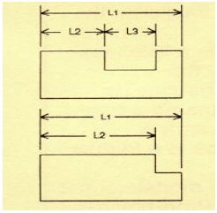
There is a software package call “IronCAD” that has claimed to have solved the parent child “Problem”. I love parametric modeling and I love ProEngineer. I have been doing software modeling about 20 years and handware modelling about 9 year. I believe many software packages do deal with over dimensioning by ignoring it. If you can over dimension, many parent child relationships vanish. However, this mentality stick its head in the sand of delusionality. Consider the example you gave. Comparing the first part to the second part yield a different part. If a component mates with the surface to the right of dimension L3 and suddenly that surface is gone, then the “problem” isn’t with the software, the problem is with the assembly. This “problem” is intrinsic. This is a reality. Sure, I could let this mating part dangle in space, but that is the REAL problem. Parametric models force discipline in solids modeling and assembly building. It forces you to see how things go together and that puts you in the assembler’s shoe firmly rooted in the real world. Only then and effective geometric dimensioning and tolerancing can be applied so that unintended stackup are avoided and function surfaces can be properly identified and prepared.
Give me Pro/E and I will shake the world.
“The failed promise of parametric CAD” is the article title, but I don’t see explicitly stated what the promise was or how it failed to meet that promise.
The goal that Sam had is unachievable, as are all forms of Utopia.
Then you write – “Parametric modeling wasn’t a failure.” ” What has failed is the next step in parametric modeling”
The example from Wolfe is a stupid one, not surprising given the age of the reference and the lack of sophistication of the market at the time. There is no good expected result when altering a dimension causes a critical topology change.
“But, still, no one has solved the inherent problems it has with
parent-child feature dependencies, and complexity of feature trees.” There are no inherent problems with dependencies. Excel spreadsheets are identical in computational background to CAD/CAE systems, but no one is arguing it is better to eliminate formulas and just type values into cells.
The contents of this article lead to a number of sources, none of which get to the underlying problem – how does one create a tool such that users don’t need to: know how it works; care how previous outputs from the tool came to be, and still satisfy unquantified or baseless needs.
Is this article on spec or was it commissioned? I’ve wondered how non-topic writing gets out there and is paid for.
The problem with Synchronous is that it’s just a trademark. It works differently in NX and Solid Edge. It is a combination of several different pieces of technology.
I think systems that combine parametric and direct editing are interesting. The implementation of Synchronous in Solid Edge has gotten better over the last several years, but I’m not willing to rank it compared to, say, Pro/E, IronCAD, KeyCreator, or even CATIA. First, because the varying implementations of combined parametric/direct editing seem to all have their own strengths and weaknesses, and second, because the ProE/Creo users who are already mad at me would probably chase me down and beat the hell out of me were I to say anything remotely negative about their favorite CAD system.
Sorry I wasn’t more explicit. I called out the “failed promise” in the title and first paragraph of the second part.
The example from Wolfe was a simple one, not a stupid one. It’s been well demonstrated in the last 5 or 6 years that it’s possible to handle topology changes as special cases, and actually do something sensible and useful in those cases.
The inherent problems with the parent-child dependencies in parametric modeling are first that they’re unpredictable, and second that they’re often hidden, or hard to see.
If you would have read the rest of the article series (or even just this one), you’d see that I’m by no means advocating getting rid of parametrics.
The example about Excel is a fine one: Research by Ray Panko shows 88% of spreadsheets have formula errors… and one of these, in a spreadsheet created by some Harvard economists, had a role in helping to tank the world economy. Yes, there are inherent problems all right.
I’m not a proponent of trying to make CAD a tool for people who don’t know what they’re doing. I am, however, a proponent for making CAD a better tool for engineers who are experts in their domains.
The article series was neither on spec nor commissioned. But I’m curious: who do you think paid for it?
Many people have.
IronCAD is an interesting program, and is based on some really good technology.
I agree about parametric models forcing discipline. But discipline to what?
The challenge is to find a set of best practices that, are relatively easy to adhere to, and provide predictably good results.
Ok, found it. But Editing is not a failed promise. That’s what made it easy to miss.
Parent-child relationships are entirely predictable. If they weren’t then software could not evaluate them. That users are too lazy to bother to investigate the outcomes is not a problem with them. You do indicate “Direct modeling—a syncretic melding of concepts pioneered by CoCreate,
Trispectives, Kubotek (and many others)–has shown the most promise to
cure the parametric curse.” Reads like a desire to eliminate parametric modeling.
If you want an interesting investigation, look more at the assumption that unqualified software developers in the form of untrained/unskilled engineers are given tools and are expected to not understand their use.
You ask for a tool for engineers who are expert, but not in the use of the tool. Sounds like a tool for those who don’t know what they are doing.
Still no idea who pays for this. Only care to the extent of deciding if it is an advertising plug or valuable research. Seems to lean to a plug for Solid Edge.
I believe the best set of practices is centered around ASME Y14: Engineering Drawing and Related Documentation Practices. Namely ASME Y14.41-2003 ”
Digital Product Definition Data Practices” Y14.5 – 2009 Geometric Dimensioning and Tolerancing, ASME Y14.100 Engineering Drawing Practices, ASME Y14.31 Undimensioned Drawings and ASME Y14.35M. You can find a more comprehensive list at http://www.ihs.com/products/industry-standards/org/asme/drawings-terminology/index.aspx. Unless you have a good understanding of these standards, It is difficult to evaluated any CAD software. These are industry standards.
So to answer your question “But discipline to what?” The answer is discipline to the said standards! Any good CAD software should adhere to these standard.
Where you stated:
“The challenge is to find a set of best practices that, are relatively easy to adhere to, and provide predictably good results.”
is failed.
Drawings are contracts. Good drawings are enforceable contracts. It take discipline to make a good clear contract. A good drawing is clear according to the ruling language (ASME Y14). It is a language with appropriate interpretations. Outside of that, bad parts are made, folks get mad and lawyers get rich!
The standards you mention do nothing to prevent brittle parametric CAD files.
But, if you want to talk about standards, let’s look at MIL-STD-31000, for technical data packages.
Why look at MIL-STD-31000? It was canceled in 11- 2009.
Nope. MIL-DTL-31000C was superseded by MIL-STD-31000 in 11-2009, and subsequently by MIL-STD-31000A last February.
My point is that the standard provides the requirements for submitting 3D technical documentation packages. No more drawings required.
that’s too bad, because it cost a hell of lot more than IronCAD, and NX costs even more.
True, MIL-DTL-31000C was superseded by MIL-STD-31000 in 11-2009, and subsequently by MIL-STD-31000A last February. I stand corrected.
However “MIL-STD-31000 defines what elements make up a TDP; but, relies on other standards to define content and format. The TDP Option Selection Worksheet allows the selection of elements and applicable standards for a specific TDP.” according to http://freepdfdb.org/pdf/mil-std-31000-technical-data-packages-engineering-572327.html, page 9.
On page 11 of that same link it states:
” 7. Control Drawings. Control drawings need not be prepared for vendor items or nonstandard parts. Applicability of Standards. When specified on the TDP Option Selection Worksheet incorporated into the contract or purchase order, Developmental Design Drawings/Models and Associated Lists shall conform to the requirements of ASME Y14.100, or, if applicable, ASME Y14.100 and Appendices B through E, as required, ASME Y14.34, and ASME Y14.41.” Note that these are the same spec I referred to earlier. You can’t get around ASME Y14 without being recognized by the industry.
I see a lot of parametric designers here arguing the merits of parametric modeling. On the other hand, being a direct modeling CAD designer, I do not feel the need to protect the product I use which was CADKey and now KeyCreator. Perhaps that’s the most telling difference between the two.
Direct modeling let’s the designer work and create without worrying about the tools. I have tried Solidworks, and have constantly had to think what I was doing and the impact on the design based on the tools in the package.
There’s plenty to think about when you’re creating a design. The CAD software should not be one of them..