• Skip to primary navigation
  • Skip to main content
  • Skip to primary sidebar
  • Skip to footer

3D CAD World

Over 50,000 3D CAD Tips & Tutorials. 3D CAD News by applications and CAD industry news.

  • 3D CAD Package Tips
    • Alibre
    • Autodesk
    • Catia
    • Creo
    • Inventor
    • Onshape
    • Pro/Engineer
    • Siemens PLM
    • SolidWorks
    • SpaceClaim
  • CAD Hardware
  • CAD Industry News
    • Company News
      • Autodesk News
      • Catia News & Events
      • PTC News
      • Siemens PLM & Events
      • SolidWorks News & Events
      • SpaceClaim News
    • Rapid Prototyping
    • Simulation Software
  • Prototype Parts
  • User Forums
    • MCAD Central
    • 3D CAD Forums
    • Engineering Exchange
  • CAD Resources
    • 3D CAD Models
  • Videos

Leslie Langnau

Immersive Design—A virtual reality case study

February 16, 2022 By Leslie Langnau Leave a Comment

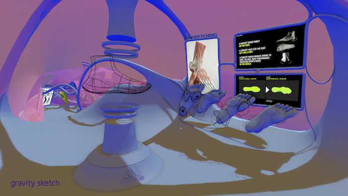
A new Adidas maker space—located inside a giant, digital sneaker—features virtual-reality 3D design tools for long-distance design collaboration.

Jean Thilmany, Senior CAD Editor

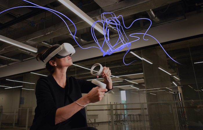
When Adidas designers were tasked with creating a seamless sneaker, they donned their Oculus headsets and got to work in the virtual world.

The team met regularly in a large, footprint-shaped studio that existed only in a virtual world entered through the Oculus. Of course, each team member was really in separate physical spaces, but with the help of the headsets and the immersive world, they felt as though they were meeting in real life.

The move dramatically slashed time spent creating an initial mock-up: from 21 days to less than one day, says Paul Sholz, Adidas senior footwear designer.

“In the design process, you create boards to inspire you and you brainstorm together. What we did in this virtual environment was the same, but we designed the actual product,” he says.

The Harden Vol. 5, the debut shoe in the Adidas Futurenatural line of molded, seamless sneakers. Credit: Adidas

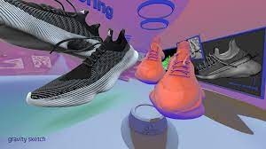
Scholz and his colleagues spoke in November 2021 at the online Around Conference. The conference sponsor, Gravity Sketch, makes a 3D-design platform hosted in virtual reality, which is the tool Adidas used to help design its Futurenatural shoes. The company gave the same name to its range of tools accessible within the immersive environment.

The one-piece, seamless sneaker line just debuted, about 18 months after the design team’s initial virtual meeting. The Futurenatural sneakers are molded rather than sewn. That is, the upper is fused to the sole with high pressure and heat to create what looks like one continual shoe, with no obvious break between the top and the bottom.

Traditionally, footwear designs often work in two-dimensions, extrapolating 2D lines to form lateral views of the proposed shoe. But building-out designs in the 3D virtual environment makes a mockup materialize more quickly, says Robert Stinchcomb, Adidas creative designer. He played a lead role in bringing the virtual system into the company.

Designers wear Oculus headsets to design in 3D with Gravity Sketch software. They feel as if the design is floating in front of them, inside a virtual world, and they can easily make updates and changes to that design. Credit: Gravity Sketch

“Now it’s down to showing up at work at nine and at 3 pm having a mockup at the point where you could see everything and talk about ‘let’s switch the layering here,’” Stinchcomb says.

The mockup is an early-stage design “almost like a napkin sketch,” he adds. “This is a place we sketch out designs before fleshing them out, before we make a sample. And we’re doing it in a room that is super collaborative where we can talk to each other even though we may not even be in the same country.”

The team can quickly come up with 10 or 15 sneaker concepts, says Arnau Sanjuan, Adidas design director, footwear innovation.

“It’s easy to see how designs would look, to play around with them, to brainstorm ideas together quickly,” he says.

The Futurenatural studio looks much like a virtual reality game. Designers move about in the virtual world—moving between a series of “stations”— the same way they would any virtual-reality game in which avatars work together.

Gravity Sketch makes a 3D-design platform hosted in virtual reality, which is the tool Adidas used to help design its Futurenatural shoes.

The first stop is for design. Here, designers create the 3D model of the shoe. Surfaces are added at a second stop. Then it’s on to detailing and rendering. All before a physical prototype is created.

Because the shoe is easy to see and understand, the finished mockup can be immediately shared with manufacturers and marketing people for their feedback. They needn’t have an Oculus, as the designs can be captured and shared via other methods. Suggested changes are quickly made within the virtual environment.

James Harden’s foot
The mockup starts with the human foot. But for Futurenatural, the company took another tack. Like many shoemakers, the company had been using a generic last—the term for a 3D model of the foot—meant to represent the common sneaker wearer. For the Futurenatural line, Adidas wanted a better fit.

Adidas scanned thousands of people’s feet, including those of professional athletes. Of course, the popular shoemaker already had prints of athletes who have promoted their own Adidas sneaker in the past. James Harden, basketball player for the Brooklyn Nets is among those elite players. The Supernatural line debuted with the player’s fifth-signature basketball sneaker, Harden Vol. 5.

The engineers pulled together all types of feet—large sizes, small, narrow, wide, to best represent the foot. From that, they developed a new “last.”

Designers make their first foray into the Gravity Sketch virtual environment to fit the last with experimental sneaker concepts. Here is where they play with articulated lines in the 3D environment, rather than extrapolating view and fit from a 2D print, Stinchcomb says. They can rotate the view to see how the shoe would look, from the top, bottom, and sides.

At this first stop in their virtual environment, Stinchcomb and fellow designers work out new ideas for a sneaker’s footpad and play around with ways the upper might be molded and pressed. They sculpt arches and add padding to the sole in areas where the foot would benefit from reinforcement.

Collaboration is a key part of this design, with the designers talking back-and-forth in the virtual world as they gesture at parts and play around together with design, Stinchcomb says.

“We take a shoe and explode it and invite people into the space and spec out every single detail. We can blow it up to the size of warehouse and they can swim around the shoe, doing a deep dive on every part,” he says.

“At such an early stage, we can discuss complex details within the form,” he adds. In fact, these early iterations hold enough information to be fleshed out even further, which takes place at the next stage, or station: surfacing.

This is where the skeleton comes together and where volumes are defined, Stinchcomb says. Here, designers wrap their shoe to simulate the material they have in mind for end use. At this step, they create a continuous, lifelike surface with the help of SmoothKit software to sharpen effects.

The team also uses Adobe Substance Painter to “get the feel of the material” and to shade the image so it looks “as realistic as possible,” says Marius Jung, senior design.

Because the footwear industry makes heavy use of Adobe Photoshop and Illustrator, these new tools were a bit of a departure for the team, he says.

“In the past, we’d spend hours creating the right shadows and lighting, and now we’re able to speed that up and dive right into detailing like we’ve never been able to before,” he says.

When designers are satisfied with the shape and look of the shoe, they move to the next area within the virtual design space. At this juncture, they add details like laces and lace loops to their continuous surface. The team then renders the illustration with KeyShot software to give the image a photorealistic, lifelike quality.

At this stage, the team can share the image with other Adidas departments, mainly marketing and manufacturing. These teams offer their suggestions long before a final virtual prototype, much less a physical prototype, is created, says Marius Jung, senior designer. Their input is important, because the Supernatural line is a step apart from the usual. Designers need to know, and need to know early: can the manufacturer make a mold for this shoe using the designated materials? Will buyers be delighted or dismayed with this form for a new integrated sole?

Members of those teams can be invited into the virtual world if they have access to an Oculus. If not, the images can be shared on a desktop, Jung says.

Adidas worked with one of its factories to develop a new production process for the new shoe. During design, representatives from that manufacturer weighed in with tooling ideas. They also offered feedback about how they might produce the welting and lace loops. Marketers made suggestions brand placement and other features.

Mutual maker space
The Futurenatural design team had been working together almost a year in March 2020 when the COVID pandemic forced many companies to move employees to home offices. Some engineering and design businesses stuttered a bit as they found new ways to collaborate outside an office.

Even people regularly tied by collaboration software might have felt a hiccup as they accessed software on their home computers, in their home spaces. Meanwhile, he and his Adidas teammates stepped right back into their familiar space -the virtual office and maker space within the virtual shoe, says Arnau Sanjuan, design director of footwear innovation.

“I’ve always been one to be in the workshop figuring things out with my hands and working with materials,” he says. “I found my work in 3D could replace those things. We work together in that world so closely.”

Scholz too emphasized the inventive atmosphere that prevailed within the digital footprint.

“The virtual space kept the creativity and the spirit alive during the pandemic,” he says. “It’s just a fun, intuitive and playful way to create serious products.”

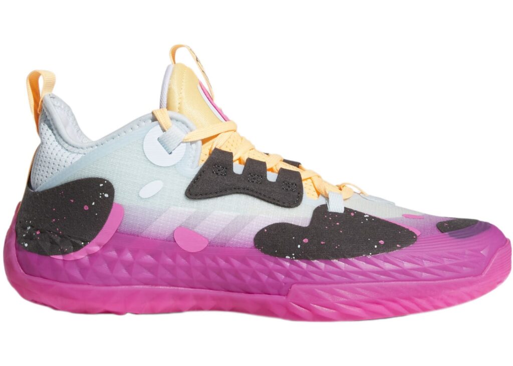
And that playfulness showed with the debut of the Harden Vol. 5 in January 2021 and the ensuing Futurenatural products, which feature polka dots, splotches and paint-like splurges in a number of patterns and colors, wavy soles, and an upper that melds seamlessly with the bottom of the shoe for an almost sock-like look.

In the future, the line is expected to include more materials and new designs. The shoes will, of course, be designed within the digital shoeprint using Gravity Plus 3D design technologies.

“The virtual reality system definitely demonstrated its value,” Sanjuan says. “Now everyone wants to try it. Because the learning curve is so easy, it’s spreading like wildfire to put 3D in anyone hands who wants it.”

Those newcomers are welcome, he adds.

“Especially at big, grand company like Adidas, it’s important to inject new processes into footwear and to look at things in a different way, Sanjuan says.

Filed Under: Simulation Software, VR software

Siemens adds intelligence-based design to Xcelerator portfolio with latest release of NX

February 14, 2022 By Leslie Langnau Leave a Comment

Siemens Digital Industries Software today launches the latest release of its NX software, part of the Xcelerator portfolio of software and services. The latest release of NX software leverages advanced technologies, such as artificial intelligence (AI) and advanced simulation capabilities, while continuing to invest in significant productivity and capability enhancements to enable its community of designers, engineers and manufacturers to innovate more quickly.

Designing in the context of the full product assembly gives confidence in component validity and allows the impact of design changes to easily be understood

“In the latest revision of NX, Siemens Digital Industries Software has smoothly woven topology optimization design from requirements, through to component generation, additive manufacturing, and final machining by leveraging their convergent modeling and automated model-based definition authoring for PMI generation together with task-based collaboration.” said Dr. Ken Versprille, Executive Consultant, CIMdata. “Users will welcome the effortless user interface that guides stakeholders through each step of the process.”

Highlights of the new release of NX software include:
• The new NX Topology Optimizer helps to create parts based purely on functional and design space requirements, resulting in fully editable convergent bodies that would be almost impossible to design and engineer manually. Inevitable design changes can be quickly made, optimizations and any downstream features updated automatically – saving time, effort and maximizing reuse of intelligence design and engineering data.
• The Design Space Explorer combines design space exploration with generative engineering to help designers automatically optimize a design against multiple objectives. Design engineers define the optimization problem with all parameters, constraints, and objectives in place and NX uses Simcenter™ HEEDS™ software to conduct multi-objective parameter optimization, providing the designer immediate set of viable design alternatives to consider that would have otherwise required a simulation specialist.
• Increased Artificial intelligence (AI) & machine learning (ML) in the Selection Prediction and Select Similar commands uses shape recognition to quickly identify geometrically similar components, while the NX Voice Command Assist allows the user to invoke commands, navigate multi-level menus and operations as well as teach the system words or phrases to carry out common tasks. Ask NX “Have we done something like this before?” and it will carry out a Shape Search using Siemens’ Geolus® technology.
• Lattice structures within NX can now be optimized using Siemens’ Simcenter 3D simulation to derive the optimal lattice structure in a singular environment – eliminating the multiple design analysis steps required traditionally. Elsewhere, Part Orientation Optimization brings nesting of parts (and their associated supports) within a machine build area along with integrated cloud-based orientation optimization processes to find the optimal build orientation for reduced thermal distortion. Siemens continues to deliver advanced capabilities in additive manufacturing that are designed to help our customers optimize their overall design and manufacturing processes.

New manufacturing techniques like Additive Manufacture can be automated to build in process intelligence such as support structure design.

“With each new release of NX, Siemens is pushing the barriers of what product development systems are capable of,” said Bob Haubrock, Senior Vice President Product Engineering Software, Siemens Digital Industries Software. “Our shift to continuous releases of NX is proving incredibly popular with our community – enabling us to deliver  capabilities more quickly than before. This means providing access to new tools and technologies so they can be applied to our customers’ design, engineering and manufacturing challenges to help them overcome them more quickly. We continue to improve the core tools our customers rely on every day, with over 1,200 customer enhancement requests delivered in this release.”

Siemens Digital Industries Software
siemens.com/software

Filed Under: Siemens Digital Industries Software Tagged With: Siemensdigitalindustriessoftware

Latest updates to Siemens’ Simcenter 3D 2022.1

January 11, 2022 By Leslie Langnau Leave a Comment

Siemens Digital Industries Software announced the latest update to Siemens’ Simcenter 3D software, part of Siemens’ Xcelerator portfolio of software and services. Among the new capabilities, Simcenter 3D offers increased support for turbomachinery modeling, a dedicated drop test application for handheld devices, tightly integrated topology optimization with the NX Design environment, and a new acoustic solution method that is up to 10 times faster than standard methods.

Siemens’ Simcenter 3D 2022.1 release focuses on helping engineers overcome challenges in four key areas:

Model the complexity: The ability to model and understand complex physical phenomena is at the forefront of this release. Simcenter 3D’s industry-leading solution for the turbomachinery industry has been extended with additional thermal multiphysics, rotordynamics and thermal fatigue capabilities to more accurately capture the complex physics happening within these machines. A new dedicated set of tools to simulate spiral bevel gears, as often found in automotive differentials, enables accurate, system-level NVH analysis on these mechanisms to reduce gear whine. Additionally, a new dedicated application simplifies and streamlines the drop-test simulation process for electronic and other handheld devices for engineers who are not simulation experts.

Time varying thermal fatigue helps you understand durability over real operational cycles and reduce modeling time by reading temperatures and stresses/strains from FE results.

Explore the possibilities: Acoustics auralization capabilities allow engineers to not only simulate but also listen to the acoustics/sound within the context of the end-user’s experience. Engineers can now mix all contributing sounds and listen to the combined acoustics results to answer questions such as “What will a loudspeaker sound like when you put it in a car and combine it with background noise from the engine, HVAC, wind and road?” In this release, topology optimization is now more tightly integrated with the NX Design environment so that simulations are ‘replayable’ and become easier for designers to create lightweight, yet structurally capable designs.

Get acoustics results up to 10X faster with new high performance boundary element method with adaptive order solution (BEMAO).

Go faster: Two core updates enable our customers to break new ground more quickly than ever before. The new high-performance boundary element method with adaptive order solution (BEMAO) used for acoustics simulation is up to 10 times faster compared to the standard boundary element method, while new load case filtering for aerostructures allows engineers to quickly determine the final critical list of load cases from the thousands of load cases experienced in an airframe.

Topology optimization capabilities for designers have an even tighter, more intuitive integration within the Siemens’ NX environment.
Define a flexible build plate for additive manufacturing process simulation to calculate stress build-up and see how the build plate will deform after removing the fixture bolts.

Stay integrated: Simcenter 3D now connects with Xcelerator Share for Xcelerator as a Service (or XaaS) subscribers. The Xcelerator Share collaborative cloud environment helps users or distributed workgroups seamlessly share files and communicate results to aid ad-hoc collaboration. Finally, engineers can now launch simulations remotely to any workstation or HPC cluster right from their desktop.

Siemens Digital Industries Software
siemens.com/software

Filed Under: Siemens Digital Industries Software, Simulation Software Tagged With: Siemensdigitalindustriessoftware

Ansys offers a way to protect your Christmas ornaments

December 27, 2021 By Leslie Langnau Leave a Comment

By Spencer Crandall

Around this time each year, families around the world gather to decorate their Christmas trees. Unfortunately, we’ve all lost an ornament to a clumsy family member, a domestic pet, or a sagging tree. In the spirit of protecting the sentimental ornaments in our lives, we’re going to use Ansys to discuss the topic of safely decorating with glass ornaments. We’ll do this by using the Ansys drop test wizard ACT extension to look at a representative glass ornament falling from varying heights. We’ll go over some simple considerations during setup, material models available, and ultimately what height you can safely drop a glass ornament and expect it to survive.

Jumping right into the tools that we’ll need to run this drop test analysis; we can go into our ACT manager and make sure that the Mechanical Drop Test Wizard ACT extension is loaded.

Next up will be finding the proper materials for our model. Thankfully, Ansys includes a library of explicit material models, which we can use in lieu of hunting down the complex, rate-dependent, brittle response, material properties that we will need. We will be using the Floatglass material, which uses the Johnson-Holmquist Strength model. This material model will allow us to show plasticity and damage along with material fracture.

Moving into the explicit module inside of Ansys Workbench, we’ll launch the Drop Test Wizard, which will expedite the setup process. This can be found in the Environment context menu when you have the Explicit Dynamics object selected in the outline.

1. Using the Drop Test Wizard we can complete the following steps:
2. Orientation of the target surface and imported geometry
3. Creation of the target surface
4. Meshing
5. Set initial velocity based on drop height
6. Set analysis end time and analysis preference to Drop Test
7. Establish body interaction contact behavior (frictionless or frictional)

With the setup described, we can iterate on our drop height until our glass ornament experiences a failure as shown in the following GIFs (click on each to play).


Our analyses indicate that you can safely hang your glass ornaments no higher than 40 inches. Keeping that height restriction in mind will help you and yours keep safety at the forefront of all your Christmas tree decorating parties.
Spencer Crandall, Simulation Specialist – FEA at Rand Simulation
Spencer is an experienced mechanical engineer with a demonstrated history of leading technical programs in the aerospace industry. He has a strong background in additive manufacturing, mechanical design, value and process engineering, and FEA (ANSYS APDL).

Filed Under: Ansys Tagged With: ANSYS

Using simulation to ensure multimode pacemakers synchronize communications

December 15, 2021 By Leslie Langnau Leave a Comment

By Dixita Patel

Recent advances for pacemaker technology include improved electronics and smaller batteries, making the development of leadless cardiac pacemakers (LCPs) possible. An LCP is a self-contained (capsule-like) generator and electrode system that eliminates the need for pocket or transvenous leads that often cause malfunctions. The current LCPs on the market pace at a single location of the heart, but for patients who require more than single-chamber stimulation, a multinode LCP system (Figure 1) can be used. Multinode LCP systems require synchronization between all of the implanted devices to function properly. However, the standard communication techniques used may be unsuitable due to constraints in terms of power consumption and size.

To help make the system and communication more efficient, researchers at MicroPort CRM are using simulation to investigate these design challenges using galvanic intrabody communication (IBC). IBC provides a power-optimized solution to facilitate communication between devices, which in turn helps to synchronize multinode LCP systems.

Multinode LCP system with two implanted capsules. The heart figure has been modified and reprinted by permission of Pearson Education, Inc., New York, New York.

Intrabody communication transceivers for LCP applications

Intrabody communication (IBC) is a near-field communication method that uses an electrode pair to send an impulse through body tissue to a second electrode pair that receives the signal. This method works with ultralow power, and no additional antennas are needed because the electrodes used for pacing also provide the electric field for the communication.

Mirko Maldari, an electronic engineer at MicroPort CRM, and his team proposed a new methodology to further characterize these types of communication channels. “With IBC, because electrodes are used to communicate [instead of coils and antennas], we can optimize both power consumption and size,” said Maldari.

In their research, an in vivo study was performed using a system that consisted of two capsules that were implanted in the right atrium and right ventricle of a heart shown in Figure 1. Further analyses involved the COMSOL Multiphysics software to measure the attenuation of the channel and estimate how much power is dissipated in the tissue.

Analyzing IBC pathloss with simulation

The team at MicroPort collaborated with Synopsys Inc., an electronic design automation company, using the Synopsys Simpleware software to develop a model of a human torso that would be importable into the COMSOL Multiphysics software (Figure 3). The model is based on a validated human phantom from IT’IS Foundation Zurich; more specifically, the “Duke” model, which represents a 34-year-old male.

LCP prototype for IBC channel studies.

The geometrical model was created to include organs, muscles, bones, soft tissue, and cartilage. After importing into COMSOL Multiphysics, an approximated version of the heart chambers was built to distinguish heart muscle from blood. Maldari said: “It was important for my application for these features to be included because they have different electrical properties.” The team then designed two identical LCP capsules in COMSOL Multiphysics to estimate the attenuation levels of the intracardiac channel.

Torso CAD model imported into COMSOL Multiphysics; cross-sectional view.

The capsules were studied at two different orientations, both at a channel distance of 9 cm. Simulations were performed with a quasistatic approach using the Electric Currents interface in the AC/DC Module, an add-on product to COMSOL Multiphysics, to calculate the channel attenuation in a frequency range between 40 KHz and 20 MHz. The results in Figure 4 show the positions of the right atrium (RA) capsule of the worst-case scenario (perpendicular) and the best-case scenario (parallel). The best-case scenario shows a higher differential voltage across the receiving dipole. The attenuation levels of both scenarios can be seen in Figure 5, where the difference is ~11 dB. From 40 kHz to 20 MHz, the attenuation decreases by ~5 dB for both cases. From the results, Maldari and his team were able to verify that relative position and orientation of the capsules strongly impacts the channel attenuation.

RA capsule positions for worst-case (left) and best-case (right) scenarios.


For MicroPort, it was important to estimate the attenuation levels before preparing the prototype. “As researchers and scientists, we try to reduce the amount of animal trials, and simulation has allowed that,” said Maldari. “It is a powerful tool to estimate the behavior of the signals within biological tissues before investigating them experimentally.” The use of simulation allowed the team to define accurate models for galvanic IBC communication and optimize transceivers for LCP systems.

Attenuation levels of the intracardiac channel for both scenarios.

Future plans for IBC

MicroPort’s future plans involve further studies, where the effect of certain input parameters — such as the electrode size and dipole lengths — on a more complete set of electric field parameters will be investigated. This would help them point out the attenuation difference between diastolic and systolic periods. As of now, the researchers are working on the design of an ultralow-power receiver for LCP synchronization purposes. The new receiver could potentially mark groundbreaking innovation for dual-chamber pacemakers.

COMSOL
www.comsol.com

Reference
Maldari, Mirko, et al. “Wide frequency characterization of Intra-Body Communication for Leadless Pacemakers”, IEEE Transactions on Biomedical Engineering, vol. 67, no. 11, pp. 3223–3233, 2020.

Synopsys and Simpleware are trademarks and/or registered trademarks of Synopsys, Inc. in the U.S. and/or other countries. COMSOL Multiphysics is a registered trademark of COMSOL AB.

Filed Under: COMSOL Tagged With: COMSOL

Designing out loud

December 15, 2021 By Leslie Langnau Leave a Comment

Voice and haptic feedback could ease CAD complexity speed design but is slow-to-market due to that very CAD complexity.

By Jean Thilmany, Senior Editor

“Computer, draw me a circle.”

You won’t be saying that to your computer-aided design system anytime soon. Even as Alexa and other speech-recognition systems have become ubiquitous over the past decade, voice-controlled CAD remains elusive.

Developers say design software that responds to verbal commands could cut the learning curve, make it easier to work with a system, and slash design time.

Perhaps it’s no surprise that voice-controlled CAD isn’t here. CAD is vastly more complex than the speech recognition tools we use today. Asking Alexa to turn up the thermostat or dictating a text message is very different than verbally controlling geometries, parts, and mechanical forces on a screen.

When will voice-controlled CAD be commonly available? It’s difficult to know.

Yet CAD systems that “hear” and follow commands could allow design teams to zoom in on the specifics of a CAD model and to make changes during a meeting. Designers could quickly add, remove, or update information in design databases and could quickly make routine requests, like opening a screen or drawing a circle. Down the line, they may be able to do away with keyboard and mouse and to design a model via voice command.

The concept of voice-controlled CAD is not new, but getting there is difficult.

In 2009, researchers at the University of Hong Kong proposed a method for voice-controlled CAD. A decade later, scientists at Purdue University and at two Spanish universities set out a method for using voice to capture design intent and annotation. Throughout the years, other systems have been proposed but they remain expensive to realize and implement.

Meanwhile, designers still rely on their keyboard and mouse.

Is voice practical?

An AutoCAD LT user echoed this frustration, asking in mid-2020 in the software’s community forum why voice-command wasn’t a feature on the CAD program.

While an AutoCAD image is depicted here, you can’t verbally ask any CAD system today to draw you a circle, much less to create and combine parts for the complicated assemblies used for heavy equipment. Credit: Autodesk

“Voice command could result in titanic time savings. Consider the chains of actions that could be bypassed by a single voice command,” the user wrote. “Just stating a sketch sometimes requires moving your cursor to change from the manufacturing environment to design.

Why not just double mouse click and say ‘concentric circle’ or whatever your first sketch move is to be?”

Answers varied, several suggesting the user learn keyboard shortcuts and write macros to speed drafting time. Some point out the time spent voicing the words “concentric circle” could quickly be spent hitting a key for a macro to make the circle.

Others suggested training already available commercial voice-recognition technology to open the macros.

“Voice commands regarding drafting are just not practical,” one community member responded. “The only way I see voice commands being used is ‘Alexa, make a PDF and send this drawing to Gavin with subject: project voice.’”

Moving beyond today’s speech recognition systems isn’t yet practical, but would be necessary for CAD’s complexity, says Natalie Hutchins, an engineer and writer at IndiaCAD, which provides outsourcing services.

While your Amazon Echo Dot may carry out your commands, don’t expect your CAD system to respond to sound of your voice. Credit: Wikicommons

Hutchins created a table that compared the features of the voice-recognition programs from Nuance, Microsoft, and Google. None of the three could interpret spoken words in the correct context with complete accuracy, she found.

Not too long ago—though a lifetime ago by technology standards, so about 30 years—the mouse and the graphical display were huge engineering design breakthroughs. CAD came along at the same time as computer graphics programs. Both technologies allowed shapes to be depicted on the computer screen that had been dominated until then by blinking letters and numbers.

For the first time, engineers could depict images in on-screen and make quick changes to the dimensions and shapes when needed.

CAD advancements have continued apace. Three-dimensional CAD became commonplace. Analysis software is now tied too CAD so engineers can immediately analyze their designs and make changes where needed.

Ironically, continued CAD updates keep the systems from being compatible with voice technology.

Today’s designers often browse among hundreds of CAD icons and menu scripts and switch between various command panels in order to do a modeling task, write the University of Hong Kong researchers. Ascribing voice commands to each or these actions is impossible and would make the designer’s life harder, not easier.

The researchers’ paper, “Natural Voice-Enabled CAD: Modeling Via Natural Discourse” appeared in the January 2009 edition of the journal Computer-Aided Design and Applications. Sukui Xue was lead author; the paper was his mechanical engineering postdoctoral thesis.

While voice-driven CAD commands would be of “tremendous benefit,” the technical challenge of creating and implementing the technology means it likely won’t be available in the near future, Hutchins says.

Speaking in CAD talk

That hasn’t held CAD companies back from trying.

The CADmaker think3 met with some success with a 2000 software update that included a speech-enabled graphical user interface, which allowed the user to issue commands without scrolling through icons and pull-down menu trees. This reduced the clutter of dialog boxes, saved time, and increased productivity, according to the company’s marketing materials of the time.

Voice input provides designers with a third option, along with the mouse and the keyboard, for entering commands or numerical inputs. The software was able to recognize several hundred voice commands, including basics like draw, zoom, redraw, fit view, and line. The software also recognized numerical values.

Because of technology’s inevitable march forward, engineers will one day be able to design via commands spoken aloud. Credit: Wikicommons

The feature used Microsoft’s Speech Application Programming Interface version 5.0, an interface for third-party application developers, according to think3.

But as it added functionality to the new release, think3 had to steer a careful path between complex CAD and ease-of-use, since the company cites simplicity as a major selling point, the University of Hong Kong researchers say.

The California CADmaker closed its doors in 2011, though the move had nothing to do with its system’s voice-recognition capabilities.

In 2005, Enact Technologies introduced Speak4CAD, compatible with AutoCAD software. During beta-testing, the software doubled CAD productivity, as measured by comparing manual drawings to those created by spoken drawing commands and dimensions, said Bruce Swan at the time. He was Enact Technology senior partner at the time.

The technology was specifically written for AutoCAD commands to make it faster than standard speech-recognition software that must search for terms, Enact wrote in its marketing materials at the time. The user would dictate commands and numbers as they move the mouse, to eliminate the use of the keyboard.

Enact Technologies is no longer around. It’s not clear whether the business folded or was purchased by another company.

The think3 and Speak4CAD systems relied on predefined, targeted words and phrases, which allowed users to use relatively complicated expressions such as “view from left” and “add a circle,” Xue writes.
“However, this method still restricts the user’s expressive style by all of pre-defined rules,” he and his teammates write in the paper. Users must also remember all the fixed words and expressions.

“This impedes the freedom that might have been brought by speech, because too many restrictions have been added to the users’ expressions,” the researchers say.

They put forward a verb-based semantic search approach that would extract useful information from voice-issued sentence commands. Users would say: “draw me a circle that has a radius of 2.5 inches.” Rather than “circle; radius; 2.5 inches.”

“Natural voice-enabled CAD frees CAD users from the buttons and menu by allowing natural discourse as the input. Natural discourse is also less restricted than the previous voice-based systems,” the researchers state in their paper.

Despite these merits, their system has limitations, they acknowledge. Because it doesn’t eliminate the mouse, those with paralysis or other types of disabilities can’t use it. Also, it should recognize more natural phrasing and should be able to be used without training, the researchers say.

Their proposed system isn’t yet included within commercially available CAD software.

Annotation while speaking

In the face of technical limitations of using voice for design, some researchers are looking at voice-driven 3-D annotation to aid collaborative design, as voice-annotation may be easier to develop and implement than voice-driven design.

Annotation enables the exchange of design intent and rationale with other users directly through the 3-D model, says a research team of mechanical and construction engineering professors from Purdue University in Lafayette, In., and from Jaume I University and the Valencia Polytechnic University in Spain.

Their paper, “A voice-based annotation system for computer-aided design” appeared in the April 2021 edition of the Journal of Computational Design and Engineering.

Much of the information generated during the product design process is unstructured, writes Raquel Plumed, lead author and mechanical engineering professor at Jaume I University. That is, much of the design information is exchanged verbally and isn’t captured within the CAD system.

This information takes the form of facts, suggestions, informal conversations, discussions, and opinions.

Such information—communicated during informal conversations or even formal meetings—can be critically important for data integration, collaboration, process efficiency, productivity, and error reduction, she and her colleagues write.

“But the knowledge is often not captured or archived for future use because the process is time consuming, inefficient, and not cost efficient,” they say.

The researchers give the example of design rationale, which aims to capture information about the reasoning, motivation, and justification for design decisions and to describe their relation to other decisions.

Much of this might take place during a quiet conversation between two engineers. But it’s time-consuming to write down and store verbal conversations and then to find them again.

“Furthermore, engineers and designers often used vague expressions in their verbalizations of a problem or a design approach, particularly during the early stages of the design process, which makes it difficult to establish semantics in CAD models,” they say.

They put forward a voice-based software to annotate 3-D models directly within CAD software.
Their method automatically captures audio signals and transcribes them to a 3-D note, which is attached to the geometry in the right spot and is available to other product information and business processes across the enterprise, such as a product management system.

These researchers join others in describing how CAD systems could best incorporate voice commands. Still, voice-activated CAD remains out of reach, likely due to cost and complexity.

Or, as one user put it in the AutoCAD LT forum: “Unless commercial CAD systems adopt voice technology, we won’t be seeing it anytime soon.”

AutoDesk
www.autodesk.com

Filed Under: Autodesk Tagged With: Autodesk

Waste Not

October 28, 2021 By Leslie Langnau Leave a Comment

Engineering software helps products get greener.

Jean Thilmany, Senior Editor

For at least the past decade, the makers of design software have been touting the role their products play in sustainable design. New United States’ environmental regulations mean that conversation isn’t ending anytime soon. In fact, designers have found software can help them cut waste, aid sustainable design efforts, and boost budgets all at once, something they’d once thought impossible.

In August, Oregon passed the nation’s second extended producer responsibility law (EPR) law for packaging. Maine had voted in favor of an EPR law one month earlier. Under these laws, most product manufacturers must reduce packaging waste and become a member of a producer responsibility organization. In Oregon, PROs will need to submit an EPR plan to the state’s department of environmental quality by March 2024 and begin implementation of the plan the following July.

While environmental design—also called sustainable design—is driven by much more than rules and regulations, environmental design considerations will continue to grow, say the makers of computer-aided design and other types of engineering software. In response, they’ve added more sustainable design features to their systems.

But will the makers of products that range in size and complexity from refrigerators down to button batteries change their designs in light of new laws and increased public emphasis on environmental design? Possibly finds past research from the Resources for the Future, a Washington D.C. nonprofit with the mission to improve the environment, energy, and natural resource decisions. Cause and effect—law and design changes—are hard to link, the report found.

But even without legislation, manufacturers are heeding customers’ cries for greener goods.

Alice is a zero-emission, all-electric aircraft under development at Eviation Aircraft, which expects the plan to make regional flights more affordable. (Eviation Aircraft.)

“The extent to which EPR policies lead to design for the environment is an open question,” wrote Margaret Walls, then a researcher at Resources for the Future, in a 2006 report. The term “extended producer responsibility” was coined when the original German packaging take-back law was passed in the early 1990s, Walls wrote. “Although EPR means slightly different things to different people, a core characteristic of any EPR policy is that it places some responsibility for a product’s end-of-life environmental impacts on the original producer and seller of that product.

“The thinking behind this approach is that it will provide incentives for producers to make design changes to products that would reduce waste management costs. Those changes should include improving product recyclability and reusability, reducing material usage, downsizing products, and engaging in a host of other so-called design for environment activities,” she wrote.

Her report set out to find whether the early EPR laws had led to design changes. At the time, documentation was sparse on “real-world changes made in response to policies.”

Walls found that, in Germany, packaging volumes and materials use had declined after the EPR regulations went into effect. In Japan, Honda increased the proportion of materials within their vehicles that can be recycled in response to a law mandating auto shredder residue—the mixed material left over for disposal after vehicle parts have been recycled—meet specified recycling rate targets.

Manufacturing makes the mix

Today’s sustainable design practices go beyond the actual products themselves to encompass manufacturing methods. CAD helps here because manufacturing decisions begin with product design, researchers say.

The term environmentally conscious manufacturing process (ECMP) refers to the integration of environmental thinking into new product development, say researchers at institutions in France and Tunisia.

“ECMP has become an obligation to the environment and to the society itself, enforced primarily by governmental regulations and customer perspective on environmental issues,” writes Raoudha Gaha in a 2015 paper published in the International Journal of Advanced Manufacturing Technology. “This is especially true in the CAD phase, which is the last phase in the design process. At this stage more than 80% of (manufacturing) choices are made.”

Designers at Bresslergroup Innovation, literally designed a better (at least from an environmental standpoint) Victor Mousetrap from the Woodstream company. Woodstream

Gaha is a mechanical engineering professor at the University of Technology of Compiègne in Compiègne, France. He teamed with researchers at the National Engineering School of Monastir in Tunisia and at Ecole Centrale in Paris on the study.

Engineers should take a product’s geometry and machining information into consideration as they work within CAD software, Gaha writes. The researchers propose an ECMP approach to eco-design that calls upon CAD technology.

 Will it fly in Earth-friendly style?

Elsewhere, engineering technology providers have introduced solutions intended to aid with the design of products that are themselves specifically billed as environmentally friendly.

Take the example of the zero-emission, all-electric aircraft under development at Eviation Aircraft of Israel, which introduced a prototype of the plane, named Alice, in 2019. With a proposed cruising speed of 280 miles per hour, the nine-passenger airliner will be an affordable and sustainable option for air travel, says Omer Bar-Yohay, Eviation Air chief executive officer. Because electric engines offer higher propulsion efficiencies and lower maintenance costs, the plane’s flight costs are reduced by around 90% as compared to similar, traditionally made aircraft “which makes flying regional distances affordable,” Bar-Yohay says. Because the plane is electric, it’s quieter than a traditional plane.

Once commercialized, Alice will be capable of carrying two crew members and nine passengers on a single charge for 650 miles at 10,000 feet, he adds.

Engineers at Eviation Air where able to create the Alice prototype in two years with the help of “Reinvent the Sky” engineering software, which sits on the cloud-based 3DExperience platform from Dassault Systèmes, Bar-Yohay says. The platform integrates 3D design, composite design, and flow simulation.

More than 160 suppliers and partners located all over the world collaborated on the project.

“The propellers are made in the US, the plane’s molds in Indonesia, the landing gear in Italy, other components in France,” Bar-Yohay says. “The engineering technology allowed us to collaborate and go from concept to prototype very quickly.”

Sustainable by choice

Environmentally friendly needn’t be the size of an airplane.

The new era of innovation will come from sustainable solutions, proudly declares a director of innovation at a company that could be said to manufacture a rather fusty, noninnovative product.

While the door locks and access controls Assa Abloy makes are not quite as alluring as an electric aircraft, they’re of even greater necessity.

Recently, the manufacturer sought to introduce sustainable design practices for its products. In order for these systems to be included on green-building designs, the company needed to provide an Environmental Product Declaration to its customers.  Builders need the EPD information to attain environmental certification, says Markus Bade, Assa Abloy’s director of innovation for central Europe.

Yakima engineers redesigned their company’s ForkLift roof-rack bike with the help of software that alerted them to areas of material waste they could trim. Yakima

For the first step toward gathering the information, the manufacturer conducted a baseline sustainable engineering study on an existing product. This was done to assess and compare the environmental impacts of existing and modified designs. For the study, the company’s engineering team in the Netherlands used the sustainability solution that can be included with SolidWorks 3D CAD software, Bade says.

Although SolidWorks Sustainability estimates the carbon footprint, energy consumption, and water and air impacts associated with a particular design, the construction industry requires additional environmental data for an EPD. Nevertheless, by providing these figures, the software gave engineers a trusted starting point for sustainable design, Bade says.

The Assa Abloy designers then used the environmental impact assessment tools within SolidWorks to design a new door-locking mechanism that cut the existing product’s environmental impact and also reduced manufacturing costs by 15%, Bade says. In fact, those two results were connected on one another, he adds.

The re-designed product proved the “traditional business view of sustainable design” wrong, he says. Sustainable design practices can improve processes and save money.

“We were pleasantly surprised to learn that by evaluating the environmental impact of a product, we can cut costs and protect the environment,” he says.

Analysis of the existing product found it to be overly strong, so engineers felt confident enough to go ahead with changes to material weight and thickness, Bade adds. The team cut the number of materials used and replaced custom nickel- and chrome-plated materials with stainless steel, and redesigned the latch tail.

Other changes included closing the lock case, riveting the cover, and screwing on the front plate.

“The material savings are quite dramatic,” Bade says. “When you cast nearly a million metal parts each year, every gram that you can cut from each part means less impact on the environment and lower cost.

Another developer, Sustainable Minds, makes software intended to give engineers pertinent supplier and material information, which allows them to weigh each design decision from an environmental standpoint.

Take Yakima. The customers who buy a ForkLift roof-rack bike mount made by the company are, for the most part, already environmentally conscious. The fork-style roof rack bike mount fits nearly every bicycle crossbar right out of the box without adjustment. To make the product even more environmentally appealing, Yakima used the Sustainable Minds software to find places environmental improvements could be made to its forklifts, says Chris Sautter, advanced development manager at the company.

The sustainability software highlighted the areas where engineers could make material substitutions that significantly improved sustainability and also improved cost and performance, Sautter says.

Reduce the wrappings

When it comes to retail products, sustainable packaging and manufacturing processes don’t necessarily need to be separate, designers have discovered.

The product development firm Bresslergroup Innovation, headquartered in Philadelphia literally designed a better mousetrap—and its packaging—with help from Susainable Minds software. When Woodstream learned its Victor Mousetrap may have a place in the aisle at Walmart, the supplier knew a high score on the retailer’s environmental scorecard would further the mousetrap’s chance of acceptance.

To boost the rating, Woodstream called in Bresslergroup Innovation, which kicked off redesign using the Sustainable Minds evaluation process, says Mathieu Turpault, director of design and managing partner at Bresslergroup.

“The software enabled us to create a benchmark, a starting point that we could iterate around and improve upon. We could quickly test assumptions, evaluate how shipping environmental impact compared to material environmental impact, and figure out where our design time and effort should be spent,” Turpault says.

After improving on the product’s design, Bresslergroup turned its attention to packaging. Designers were able to eliminate the plastic blister pack and minimize the amount of cardboard the mousetrap had been packaged in.

The designers discovered early that the environmental impact of shipping the mousetrap to retail locations was fairly minimal. Material selection was a more important element for sustainable packaging.

“It became clear that removing material from the packaging design would yield significant environmental gains,” Turpault says. “Sustainable Minds helped guide our design process throughout.”

Maybe the mousetrap maker is leading the way, showing manufacturers in Oregon and Maine that they can reduce packaging waste to meet the new environmental legislation in those states. It may also demonstrate that sustainable design practices don’t need to increase costs while raising the changes the product could appear on retailers’ shelves or as a construction material within certified green buildings.

And the practices will give the environment a break as well.

Filed Under: Aerospace, CAD modeling

Autodesk Fusion 360 App Version 2.0 gives instant manufacturability feedback

October 20, 2021 By Leslie Langnau Leave a Comment

Xometry, Inc., a leading AI-enabled marketplace for on-demand manufacturing, announced the launch of version 2.0 of its app for Autodesk Fusion 360. The app is free and can be downloaded directly from the Autodesk Fusion 360 App Store.

Updated with new features in addition to the instant price and lead time capabilities launched earlier in 2021, Version 2.0 now offers manufacturability feedback and multiple part upload features, improving processes for engineers and designers working in Autodesk. With manufacturability feedback, engineers and designers receive information on part manufacturability while they are designing in the Fusion 360 interface, allowing them to improve their designs. And with the ability to upload multiple parts, engineers can price and receive feedback on multiple parts at the same time, streamlining their work. Version 2.0 is a critical enabler for engineers looking to fast-track product iterations and incorporate real-time feedback.

Xometry offers an exclusive 10% discount on all custom parts orders placed through Autodesk Fusion 360 app in the US. The company is also rolling a European version of the app with multiple languages and pricing in Euros.

Xometry also offers an add-in for Autodesk Inventor. The Inventor add-in is available for free on Xometry’s website along with other popular CAD software add-ins.

Filed Under: Autodesk Tagged With: Autodesk, xometry

What’s in Solid Edge 2022?

October 6, 2021 By Leslie Langnau Leave a Comment

Siemens Digital Industries Software released the 2022 version of Solid Edge software, which brings embedded rules-based design automation, greater capabilities to work with point-cloud, mesh and imported data without the need for translation alongside new tools to for 2.5 axis machining and ultra-efficient upfront fluid flow simulation.

Highlights for Solid Edge 2022 include:

The new embedded Solid Edge Design Configurator adds rule-based automation and enables quick customization of products based on design parameters and rules, saving time and enabling the capture and reuse of intellectual property in intelligent models.

CAM Pro 2.5 Axis milling is now included in Solid Edge Classic, Foundation and Premium for customers with active maintenance. Fully integrated, it maintains full associativity with design data and provides automated tool path creation combined with machining simulation to help achieve optimized machining operations.

New CAD Direct capabilities allow insertion of third-party data formats without the need for translation while maintaining associativity. Solid Edge 2022 continues to integrate Siemens’ leading Convergent modeling technology, allowing users to mix b-rep and mesh geometries in the same model, again without conversion, making mesh data more useful and reducing product modelling time. Full-color point cloud data can also now be used for visualization purposes directly within Solid Edge, especially useful when retrofitting factories or plants, allowing the positioning of design equipment in the context of the point clouds.

Solid Edge 2022 is available through Xcelerator as a Service, providing access to Siemens’ next-generation, cloud-based collaboration solution including Xcelerator Share, that brings design-focused capabilities (such as 3D/2D CAD view/markup), augmented reality and secure project-based sharing to the Solid Edge community.

Assembly modeling is a constant focus and the 2022 release of Solid Edge delivers the third straight release of improvement. The new Assembly preview mode reduces the amount of data that is loaded, while the multi-body assembly modeling mode is a new environment to model internal components within an assembly file. When it comes to locating those hard-to-find parts, the new component finder puts intuitive search at the fingertips with auto-complete suggestive filters.

Finally, Solid Edge 2022 introduces Simcenter Flomaster for Solid Edge software, which brings easy analysis of fluid and thermal flows in piping systems. System-level models are extracted from 3D models (reducing preparation time by up to 90 percent). Built-in wizards guide new users towards successful results while retaining advanced capabilities, such as simulation of rapid dynamic events and pressure surge, for experienced users.

Siemens Digital Industries Software
www.sw.siemens.com

Filed Under: Siemens Digital Industries Software Tagged With: Siemensdigitalindustriessoftware

Model-based definition or the perils of disconnected detours

September 27, 2021 By Leslie Langnau Leave a Comment

By Brian Thompson, DVP and GM, CAD Segment, PTC

When I speak with manufacturers, they often tell me that moving towards becoming more model-based is at the top of their priority list. Initially, they might have started down this path to eliminate the extra work required to build 2D drawings off of their 3D models. Now, manufacturers want to make the 3D model itself the gravitational center. The disconnect between the 2D drawing and 3D model is hobbling both their internal efficiency and external competitiveness.

More formally known as model-based definition, MBD is about creating rich “Technical Data Packages (TDP),” which include the 3D model and associated data elements. At the core of the TDPs is the 3D model, along with its associated dimensioning and tolerancing to clearly communicate design intent and geometric form control. Thanks to the TDP, users who sit downstream from engineering can understand and use that model without needing separate 2D artifacts – the information is in the model itself.

MBD is not another way of spelling ‘paperless engineering,’ as if mere convenience were the reason for such a strategic shift. The manufacturers we work with are talking about a broader and grander idea: a different way of approaching the product development, manufacturing, delivery, operations, and service processes so that the 3D model is the source authority.

By implication, these manufacturers are also talking about innovation, and how they might use breakthrough technologies such as simulation, additive manufacturing, and generative design to design better products faster. MBD is as much an approach to corporate strategy as it is an approach to design, product development and manufacturing.

That’s the exciting part – the vision that gets people to commit their time and resources to the effort. I would offer this advice to those who aspire to a model-based journey. Think of a rock climber scaling a cliff face. As he or she ascends, that climber will need to put an anchor in the rock through which to pass the rope.

Your 3D model is that anchor. Start there.

3D model as Anchor
This is no getting around it: every MBD journey starts by looking at your modeling practices and ensuring that your model truly reflects your design. One customer discovered, as they implemented MBD, that they had to train their engineers to know where and how to apply drafts to their injection molded parts, instead of relying on the manufacturing team to do it. Another found that simulation results would be inaccurate unless certain critical features were modeled in complete detail, instead of leaving some geometry details to notes.

Today, I look at the model itself as a precise database for all PMI rather than as a supporting item to create a 2D drawing quickly.

A geometrical product specification is gold for manufacturers.

A word of caution
Next, examine your own mental models and beware of outdated beliefs. We sometimes see those who have (unknowingly) gone halfway with MBD – only to stop on the manufacturing floor. In the past, a certain amount of rework was part of the design process, as was the willingness to accept change at the worst possible and most expensive time. Allow me to be candid. With MBD, your experts on the shop floor will need to learn to place the 3D model at the center of everything they do, too. This will surely help them streamline industrialization of the design, minimize mistakes, and produce the highest-quality output. This will definitely be a change for the manufacturing team, but everyone I’ve talked to has said this is worth it.

Disconnected detours
The worst choices in business are ones you don’t know you’re making. With that in mind, consider whether an MBD journey would, in fact, be less costly in time, money, materials and morale than situations such as the scenario described below.

At one manufacturer, final drawings were made into pdfs and put on a server where all could access them. Not surprisingly, CNC machines soon were decorated with marked-up pdfs showing late-breaking changes. As the model evolved, there was no way other than person-to-person to get the changes to the manufacturing floor. One employee jokingly referred to the ‘sneaker net’. The manufacturing engineers encountered the same situation, and the changes they made on the shop floor often didn’t get to the designers, who unknowingly proliferated errors.

In our opinion, becoming model-based is a journey. To prepare, commit to making the 3D model the source of all authority and then take a moment to reexamine your modeling practices. This will take time, but your reward will be more value for the investment you’ve already made, confidence that engineers can now spend their valuable time doing what you paid them to do, and circumstances more favorable to innovation. That’s what our customers are seeking.

PTC
www.ptc.com

Filed Under: PTC/CoCreate Blogs Tagged With: PTC

  • Go to page 1
  • Go to page 2
  • Go to page 3
  • Interim pages omitted …
  • Go to page 33
  • Go to Next Page »

Primary Sidebar

3D CAD NEWSLETTERS

MakePartsFast

Follow us on Twitter

Tweets by 3DCADWorld

Footer

3D CAD World logo

DESIGN WORLD NETWORK

Design World Online
The Robot Report
Coupling Tips
Motion Control Tips
Linear Motion Tips
Bearing Tips

3D CAD WORLD

  • Subscribe to our newsletter
  • Advertise with us
  • Contact us
Follow us on Twitter Add us on Facebook Add us on LinkedIn Add us on Instagram Add us on YouTube

3D CAD World - Copyright © 2022 · WTWH Media LLC and its licensors. All rights reserved.
The material on this site may not be reproduced, distributed, transmitted, cached or otherwise used, except with the prior written permission of WTWH Media.

Privacy Policy