• Skip to primary navigation
  • Skip to main content
  • Skip to primary sidebar
  • Skip to footer

3D CAD World

Over 50,000 3D CAD Tips & Tutorials. 3D CAD News by applications and CAD industry news.

  • 3D CAD Package Tips
    • Alibre
    • Autodesk
    • Catia
    • Creo
    • Inventor
    • Onshape
    • Pro/Engineer
    • Siemens PLM
    • SolidWorks
    • SpaceClaim
  • CAD Hardware
  • CAD Industry News
    • Company News
      • Autodesk News
      • Catia News & Events
      • PTC News
      • Siemens PLM & Events
      • SolidWorks News & Events
      • SpaceClaim News
    • Rapid Prototyping
    • Simulation Software
  • Prototype Parts
  • User Forums
    • MCAD Central
    • 3D CAD Forums
    • Engineering Exchange
  • CAD Resources
    • 3D CAD Models
  • Videos

SolidWorks

3D CAD & CAE manufacturer catalogs powered by CADENAS now available in SOLIDWORKS Electrical 3D

October 29, 2021 By WTWH Editor Leave a Comment

Good news for all electrical engineers and component manufacturers: SOLIDWORKS Electrical 3D joins the long list of software solutions for CAD, CAE, PLM and simulation that offer direct access to thousands of digital manufacturer catalogs powered by CADENAS. Millions of manufacturer-verified 3D CAD and CAE data are now directly integrated into the popular solution for electromechanical design. By integrating the Strategic Parts Management PARTsolutions, users have access to not only the countless 3D CAD models. They also benefit from an extensive selection of standards as well as intelligent functions for managing and finding proprietary, purchased and standard parts.

Optimized cooperation between MCAD and ECAD divisions
The electrical design situation is different from mechanical design, where not only, but above all, the geometries of the digital components are decisive. Electrical engineers need information about circuit diagram symbols, connections, component types (connector, cable, standard component, terminal, etc.) or parent-child relationships when selecting the appropriate component. The product models must also provide information on which connectors are compatible or how the installed components are to be correctly dimensioned in relation to each other. If this data is not stored within the CAD model, it must be compiled in a time-consuming process from various sources. Multi CAD capable product data based on CADENAS technology enables seamless collaboration between ECAD and MCAD, as component information can easily be transferred between mechanical and electrical design – without loss of information.

SOLIDWORKS Electrical 3D by Dassault Systèmes provides additional support for smooth electromechanical collaboration. With the software module, design data of circuit diagrams can be integrated bidirectionally into the 3D model of a machine or assembly. ECAD components such as wires, cables and harnesses can be easily positioned and automatically routed in the 3D MCAD model. Design and bill of materials are also synchronized in real time, minimizing sources of error.

The software indicates which connectors are compatible or how the installed components are to be correctly dimensioned in relation to each other. If this data is not stored within the CAD model, it must be compiled in a time-consuming process from various sources. Multi CAD capable product data based on CADENAS technology enables seamless collaboration between ECAD and MCAD, as component information can easily be transferred between mechanical and electrical design – without loss of information.

Dassault Systèmes
www.3ds.com

Filed Under: Dassault Systemes, SolidWorks Tagged With: dassaultsystemes

Developing a Parametric Model of a Bicycle and Human

January 25, 2021 By Leslie Langnau Leave a Comment

A general-purpose parametric SolidWorks model has been created to enable rapid evaluation of novel bicycle concepts. It can be used for ergonomics, checking clearances, aerodynamics, kinematic and degrees of freedom studies, and product visualization.

Dr. Jody Muelaner, PhD CEng MIMechE

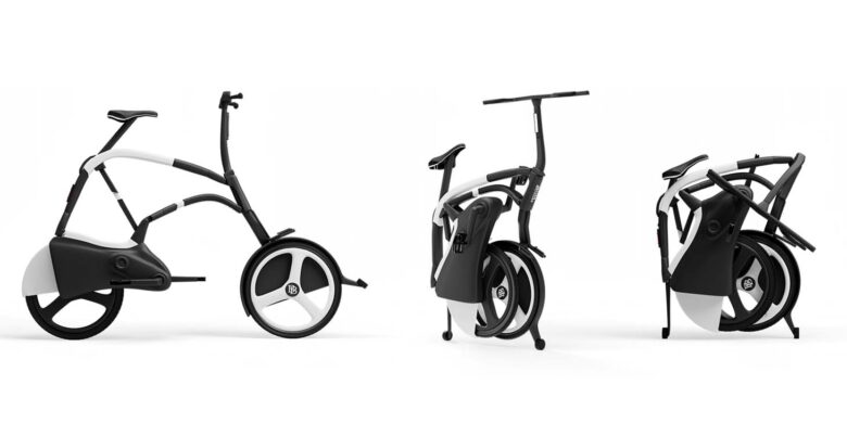
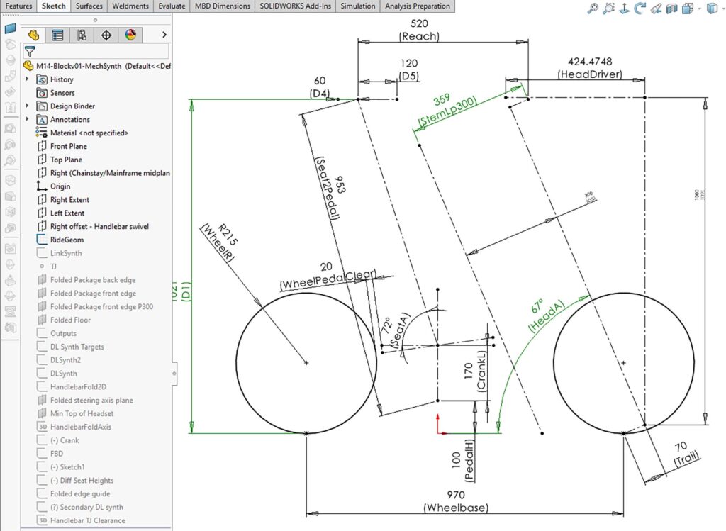
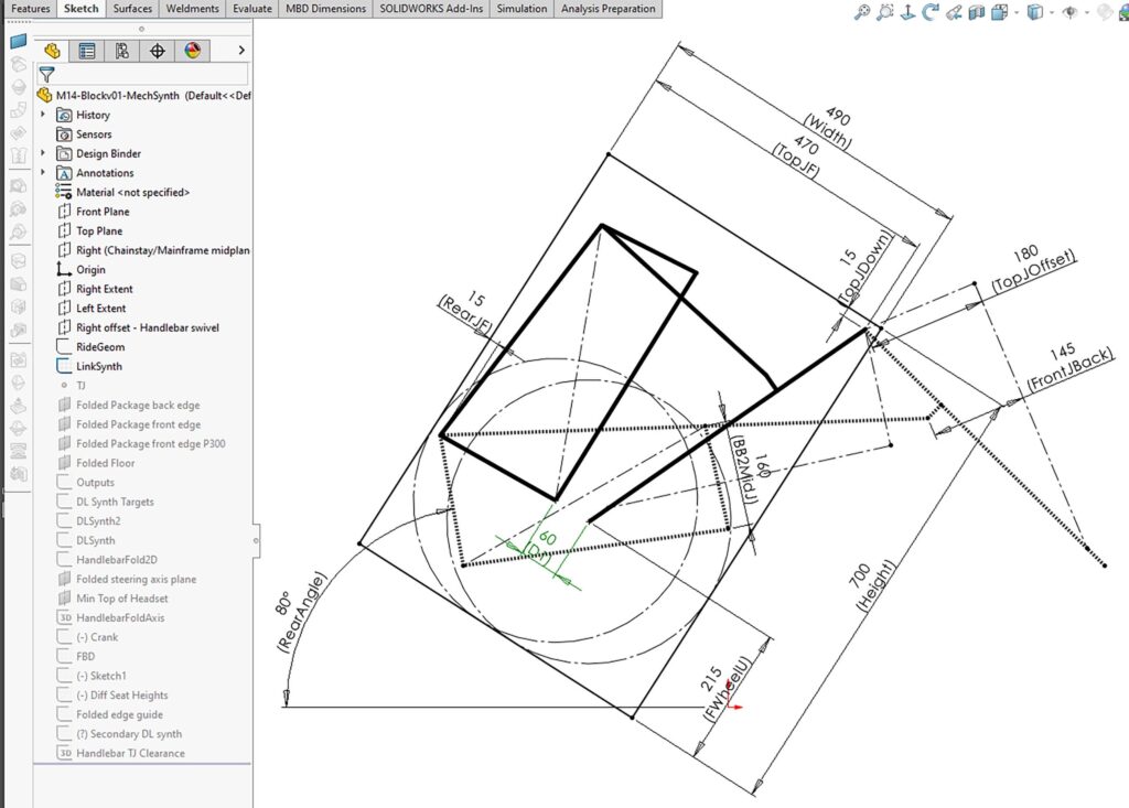
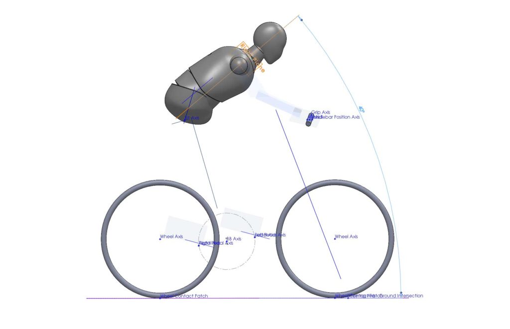
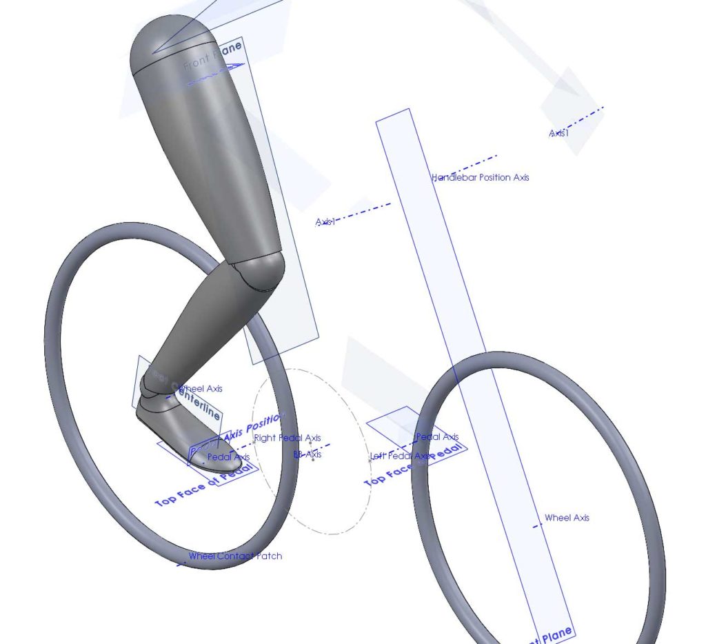
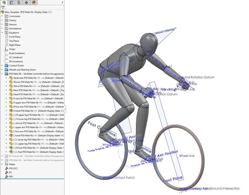
For this study in ergonomics, a set of anthropometric models from 3D Human Model were used as the starting point. Key bicycle geometry was defined using reference geometry in individual part files, located using distance and angle mates. This geometry includes the contact points at the saddle, handlebar grips and pedals, as well as the steering axis and wheel positions. Anthropometric models were then configured to fit to these contact points, with a few additional angle and distance mates that allow further adjustment of the rider position. The included models represent 5th percentile females, 50th percentile males and 95th percentile males. The model is stored as an assembly template file, enabling it to be easily reused as a layout for different design concepts. It was created for the BriefBike project, which is developing a new class of folding bicycle that will effortlessly fold into a roller-case.

Key bicycle geometry
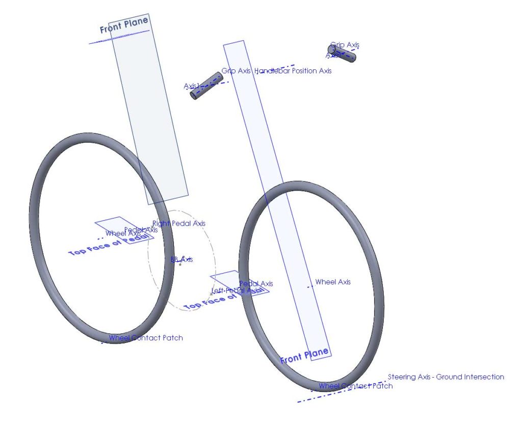
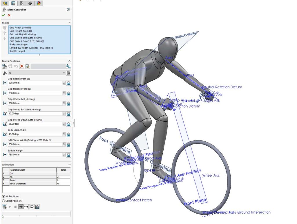
There are three ways that references can be parametrically defined within an assembly. Using a sketch or creating reference geometry (point, axis or plane) is often more straightforward and, in the case of a sketch, allows multiple parameters to be defined in a single model tree feature. However, parameters defined in this way cannot be animated or adjusted using the Mate Controller. The Mate Controller is particularly useful within this model as it allows parameter sets for different riding positions to be stored independently of configurations. It is, therefore, possible to apply different standard riding positions to any configurations that a are created. In order to provide this greater flexibility, parameters must be defined using distance and angle mates. This means the reference geometry is first defined with a part file, and the part is then mated in the assembly file.

The parametric bicycle geometry definitions are:

  • Planes parallel with the Right plane, defining the width of each pedal from the centerline (Right plane).
  • The crank length part three axes – the bottom bracket axle and the two pedal axles. The crank length is defined by different configurations of the part file. The part is mated on the right plane with the bottom bracket axis on the Front plane and at a distance from the Top plane, representing the bottom bracket height from the ground. This leaves the pedals free to rotate.
  • Pedal thickness parts contain a pedal axis and a plane representing the top surface of the pedal. They are mated to the pedal axes in the crank length
  • A Seat part contains planes representing the seat tube angle and the top surface of the saddle. The seat tube angle is mated coincident with the bottom bracket axis and at an angle from the top plane. The top surface is mated at a distance from the bottom bracket axis.
  • A Bar part contains an axis to represent the handlebar. It is mated at a vertical and horizontal distance from the bottom bracket axis.
  • The orientation the handlebar grips is defined in terms of two sequential Euler rotations – the backwards and downwards sweep. A separate part is used to define each rotation.
  • Grip_Sweep parts are mated to define the position and backwards sweep, with the following constraints:
    • Two translations by mating the origin coincident with the Bar axis
    • The remaining translation, the width of the grips, is defined by a distance mate between the part’s origin and the assembly Right plane.
    • Two rotations are constrained by mating the part’s Top plane parallel with Top in the assembly.
    • The backwards sweep is the only remaining degree of freedom. It is defined with an angle mate between the part’s Front plane and Front in the assembly
  • Grip parts are then mated relative to the Grip Sweep part, defining the downwards sweep.
    • All three translations are constrained by mating the origin coincident with the origin of Dum_Grip_Sweep
    • Two rotations are constrained by setting the Front plane parallel with Front in Dum_Grip_Sweep
    • The downwards sweep is the only remaining angle. It is defined with an angle mate between the Top plane and Top in Dum_Grip_Sweep
  • Wheels contain an axle axis and a ground plane set at the wheel radius. Different configurations are used for different wheel sizes. Certain configurations may also include basic solid geometry to visualize the tire. The wheels are mated with the ground plane on the assembly Top plane and at distances forwards and rearwards of the bottom bracket axis.
  • A Steering Axis part contains a plane to represent the steering axis angle and an axis to represent the line where this plane intersects with the ground. The axis is mated coincident with the Top plane of the assembly. A distance mate between this axis and the Front plane of the front wheel defines the steering trail. The steering axis angle is then set with an angle mate.

Care must be taken when using angle mates. The direction in which the angle is defined can flip when changes are made to the model, causing assembly rebuilds to fail or result in unexpected behavior. These issues can usually be avoided by defining a reference entity for each angle mate, which is not defined by default. This is normally just a one click operation, by selecting Auto Fill Reference Entity.

Kinematics of the Human Models
The human model has parts or sub-assemblies for hands, lower arms, upper arms, clavicles, head, neck, thorax, abdomen, pelvis, upper legs, lower legs and feet. These 19 rigid bodies have 114 degrees of freedom (DoF) without any joints or other constraints. Joints between the body parts are either spherical, removing the three DoF for translation, or revolute which also removes two rotations, constraining a total of five DoF.

When all of the joints are added to the body parts, the human model still has 43 DoF. Considering the kinematics of the model as a whole is, therefore, overly complicated. Luckily, it can be broken down into smaller kinematic chains that behave independently. For example, each leg forms a kinematic chain which also includes the crank, and each arm forms a kinematic chain between the shoulder joint and the handlebar grip.

An understanding of how a person should be positioned on a bike was provided by Mike Veal, who created the DIY Dynamic Bike Fitting guide.

  • The hip joints should align with the plane of the seat post angle.
  • The angle of the line between the hip and shoulder joints is typically between 45° and 55° from the horizontal. 45° to 50° is usual for a road bike and 50° to 55° is typical for a more relaxed upright position. Dutch bikes can be from 65° to 90°.
  • The angle of people’s feet relative to the floor is quite personal but a typical value is 15°.
  • The leg does not completely straighten at the bottom of the pedal stroke. Typically, the angle between the upper and lower leg does not exceeds 140°. Although some literature puts this angle closer to 150° this is due to static measurements with the foot parallel to the floor. When pedalling, the foot assumes a natural angle which reduces the extension of the leg.
  • Wrists allow three types of rotation and should ideally be in a neutral position for all of them:
    • Flexion/Extension can be fixed at the neutral position, with the flat plane of the hand aligned with the forearm axis. It can be adjusted without significantly changing the position of the arms by rotating the hands around the axis of the grip.
    • Deviation is sideways movement of the hand, towards the thumb is radial deviation and towards the little finger is ulnar deviation. The neutral position does not position a griped bar perpendicular to the axis of the forearm but rather that the third metacarpal bone is aligned with the forearm axis. One study found that a natural grip results in a mean angle of 65° between the grip axis and the third metacarpal, with the grip sweeping back as though the wrist was in 25° ulnar deviation. However, the standard deviation was 7°, due mostly to variation between individuals, suggesting significant adjustability may be desirable for this aspect of the grip position.
    • Supination/Pronation: Rotation about the forearm axis is known as supination when the thumb is rotating towards the back of the hand and pronation when it is rotating towards the palm.

Kinematic chain from pelvis to head and shoulders

This section of the body is made up of the pelvis, abdomen, thorax, clavicles, neck and head. The pelvis is fixed at the saddle, but is free to rotate so that it tilts forwards. The clavicles are mated parallel with the front and top planes of the thorax, effectively forming one ridged body with the shoulders in a neutral position. Although the components could be mated in series, starting with the tilt angle of the hips and then setting the angle between each part, this would make it hard to set an overall lean angle. A reference part is therefore introduced with a plane that defines the lean angle. This part is mated with an axis through the hip joints and with an angle mate relative to the assembly Top plane.

A symmetry mate is used to apportion half of the forward lean to the pelvis tilt. The Front plane of the pelvis is the plane of symmetry. The seatpost angle and the forward lean planes are symmetric about it. The abdomen is mated parallel with the dummy lean plane, and the shoulder joints are set to be coincident with the forward lean plane.

Kinematic chain from hip joint to bottom bracket

Each leg can be considered separately, as a kinematic chain consisting of the crank, pedal/foot, lower leg, and upper leg.

These four bodies have 24 DoF, which are reduced by revolute joints at the knee, pedal axis and crank axle, and spherical joints at the hips and ankles, to leave three DoF:

  • Crank position is intentionally unconstrained to allow pedaling motion.
  • Foot angle from the floor varies between individuals but the toes are typically pointed downwards by an angle of approximately 15 degrees.
  • The spherical joints at the hip and ankle also allow the leg to rotate about an axis between these joints, so that the knee moves in a circular motion. Assuming the leg does not lock out into a fully extended position, this can be constrained by making a point on the knee joint coincident with the plane defining the pedal width.

Kinematic chain from shoulder to handlebar grip

The kinematic chain for each arm consists of the upper arm, lower arm and hand. These three bodies have 18 DoF, reduced to just two DoF by spherical joints at the shoulder and wrist, and revolute joints at the elbow and the grip of the hand around the bar. The remaining two DoF can be considered as:

  • Rotation of the hand around the handlebar
  • Rotation of the whole arm so that the elbow moves in a circular path about the axis between the shoulder and wrist joints

Setting the wrist to neutral flexion removes one DoF. This can be achieved by mating the hand’s top plane parallel with the forearm axis. There are several possible ways to remove the remaining DoF. It was found that the most practical and stable is with a distance mate between a point on the elbow joint and the Right plane of the assembly.

Adjusting and configuring the model

The assembly template contains three different anthropometric models, all configured as described above. These models represent a 5th percentile female, 50th percentile male and 95th percentile male. They can be activated by simply suppressing or suppressing the associated folders in the feature tree.

Different pre-configured body positions are also included. These are defined using a Mate Controller for each percentile model.

Conclusions

The bicycle and human model template enables the rapid evaluation of novel design concepts. Applications include ergonomic studies, mechanical clearance checks, aerodynamic simulation and product visualization. The simple parametric definitions allow easy adjustment of all the relevant variables in the bicycle geometry and rider position.

Filed Under: CAD modeling, parametric modeling, SolidWorks

Dassault Systèmes introduces SOLIDWORKS 2020

September 18, 2019 By Leslie Langnau Leave a Comment

Dassault Systèmes introduced SOLIDWORKS 2020, the latest release of its portfolio of 3D design and engineering applications. SOLIDWORKS 2020 features enhancements, new capabilities and workflows that enable users to accelerate and improve product development, from conceptual design to manufactured products.

By seamlessly connecting to the 3DEXPERIENCE platform, SOLIDWORKS 2020 addresses the emerging trends and business needs in the global marketplace that require competitive organizations to seek new levels of collaboration and agility to more quickly and cost-effectively deliver new categories of experiences to their customers.

With SOLIDWORKS 2020’s hundreds of new enhancements, users can benefit from an array of choices and opportunities to improve system performance in their daily operations, streamline workflows and extend their design to manufacturing ecosystem from the desktop to the cloud with seamless connection to the 3DEXPERIENCE platform.

Among the hundreds of new enhancements in SOLIDWORKS 2020 are:

–New Detailing mode and graphics acceleration for drawings: This mode lets users open their drawing in seconds while maintaining the ability to add and edit annotations within the drawing. Detailing mode is useful if users need to make minor edits to drawings of large assemblies or drawings with many sheets, configurations, or resource-intensive views.

–Make Part Flexible is a new capability that allows users to display the same part in different conditions in the same assembly. For example, the same spring exists twice in the same assembly, but in two different conditions – compressed and not compressed. Make Part Flexible is useful in many design applications such as springs, bellows, hinges, o-rings and just about any part that can flex or change condition.

–Improvements to SOLIDWORKS PDM, the SOLIDWORKS Electrical connector and a new SOLIDWORKS PCB connector allow for complete electronics design and data management – including the secure storage, indexing and versioning of all user data – while enabling tighter collaboration between ECAD and MCAD teams.

With SOLIDWORKS 2020, and the 3DEXPERIENCE.WORKS portfolio, the 3DEXPERIENCE platform offers a growing set of cloud-based solutions that work together to help manage every aspect of developing concepts, designing products, and manufacturing and delivering them. Solutions like 3D Sculptor, which includes the xShape (sub division modeling) application, 3D Creator featuring the xDesign (parametric modeling) application, 3D Component Designer (data management), Project Planner, and Structural Professional Engineer (advanced simulation), enable users to reduce friction in their design to manufacturing process.

As announced at SOLIDWORKS World 2019 earlier this year, all these cloud-based solutions will be part of the 3DEXPERIENCE.WORKS portfolio.

“We aren’t just bringing powerful new capabilities to the SOLIDWORKS portfolio everybody knows and loves, but also extending it to the cloud through the 3DEXPERIENCE platform, the only holistic digital experience platform in the world. We’ve built a bridge to our platform-based portfolio, empowering our users to take advantage of 3DEXPERIENCE.WORKS offerings,” said Gian Paolo Bassi, CEO, SOLIDWORKS, Dassault Systèmes. “This gives organizations the environment and the applications to truly embrace the Industry Renaissance and its spirit of discovery for new ways of inventing, innovating, collaborating and producing.”

“Since 2002, Omax has used SOLIDWORKS applications to design every part of the fastest and most precise waterjet cutting technology in the industry,” said Eric A. Beatty, Senior Mechanical Designer, Omax Corporation. “Omax will continue to innovate and develop its waterjet machines and accessories with SOLIDWORKS 2020, which offers game-changing power, performance, and collaboration in the field by opening up access to the value creation process to everyone, everywhere, on any device.”

Dassault Systèmes’
www.3ds.com

Filed Under: SolidWorks Tagged With: dassaultsystemes

Updates in CAD focus on better simulation

April 19, 2019 By Leslie Langnau Leave a Comment

While the latest upgrades to major CAD systems don’t make major changes to the way those programs operate, they do include significant updates. Here’s a look at some of the biggest enhancements and key features of these programs.

Jean Thilmany, Senior Editor

CAD packages continue to see regular updates, whether a major release, or the minor updates that happen throughout the year. Some updates include major enhancements or new features, as is the case with NX, which now includes machine learning and artificial intelligence features. The company will quit bringing out yearly NX updates, as the software is now offered on continuous release.

Other popular programs like Creo, Solid Edge, SolidWorks, and Autodesk Fusion 360 have seen changes as well. More than one company has changed the way in which they name the new versions of their software and several boast new or enhanced simulation capabilities.

Here’s a look at the most recent updates.

NX from Siemens PLM

In February, Siemens announced an update to its NX CAD software, which now includes machine learning and artificial intelligence features that, by following users’ patterns over time, come to automatically predict their next steps and anticipate their needs.

The programs do this by monitoring the actions of the user and following their success and failures. In that way, the features determine how to serve up the right NX commands and also modify the user interface accordingly, says Bob Haubrock, senior vice President, product engineering software at Siemens PLM Software.

Machine learning is increasingly used in the product design process because it has the power to process, analyze, and learn from large volumes of data, he adds. In this way, designers can more efficiently use software to increase productivity. The ability to automatically adapt the user interface to meet the needs of different types of users in various departments can increase CAD adoption rates at a company, continues Haubrock.

In another recent change, Siemens PLM Software began delivering NX using a continuous release model. This means the software updates are produced in short cycles and are released when needed, at any time.

The model gives NX users faster access to new enhancements and quality improvements, while reducing the efforts needed to effectively deploy NX, Haubrock says. “With automatic updates, customers do not have to search for updates online and will not miss critical fixes. The NX Update mechanism will automatically notify and install important updates as they become available.”

With continuous release, users can turn on “automatic updates” within their system to ensure they always receive the updates. The approach helps reduce the cost, time, and risk of delivering changes by allowing for more incremental updates to applications.

Thus, NX will no longer be identified by a release number and will only be referred to as NX. In other words, there will be no NX13.

The CADmaker says it’s the first major CAD, CAM, and analysis vendor to deliver its products in this way.
The company says the new approach will enable Siemens’ NX users to:
–Receive enhancements faster to help boost productivity
–Have a consistent schedule for updates
–Better plan for the adoption of new technologies
–Reduce deployment costs

Creo from PTC

In February PTC released Creo Simulation Live, which allows engineers to perform simulation in real time on their parametric models because ANSYS simulation capabilities have been integrated with the Creo CAD tool.

Creo Simulation Live, from PTC, lets engineers perform simulation in real time on their parametric models because ANSYS simulation capabilities have been integrated with the Creo CAD tool.

“Every time you make a change in your model, you’ll see the consequences instantaneously in the modeling environment,” says Brian Thompson, PTC senior vice president, CAD segment.

“The goal is to remove the barrier between the CAD and CAE world,” says Andrew Leedy, a PTC applications engineer. “This is targeted toward the engineer or designer rather than the analyst.”

The simulation software runs linear, structural, thermal, and modal analyses. The solver uses GPU rather than CPU for instantaneous analysis, Leedy adds. “So as soon as you make changes to the model it updates the graphics that drive the simulation.

The capability to simulate and design simultaneously helps engineers understand the implications of what they’re making, he adds.

The integrated tool also eliminates the need for the engineer to mesh the model before running a simulation and does away with the post-processing step.

The integrated simulation software from ANSYS is called Discovery Live.

“Engineers can ask ‘What if I add this hole, what will it do to the model?’” he said. “This works on top of the model, it works directly within the environment an engineer is used to.”

The CAD software does require a graphics card that supports the ANSYS tool.

Solid Edge from Siemens PLM

Solid Edge 2019 brings a new naming convention to the tool, which will now be referred to by the year in which it is released. This makes it easier for engineers to identify the release they’re using as well and to identify the products within the Solid Edge portfolio, says Ben Weisenberg, applications engineer at product lifecycle management company Prolim. Weisenberg frequently details Solid Edge updates to the CADmaker’s user community.

Solid Edge 2019, from Siemens PLM, makes it easier for engineers to identify the products within the Solid Edge portfolio. The most significant updates for mechanical designers are tools that allow engineers to model and simulate the entire production process along with the final product.

The most significant updates for mechanical designers are tools that allow engineers to model and simulate the entire production process along with the final product, Weisenberg says.

These include the convergent modeling tools that designers can use to integrate mesh models directly into their workflows. They can use these tools for the milling, casting, and molding of generative designs and 3D printed designs.

Manufacturing constraints allow engineers to optimize the weight and strength requirements of their model. A new design-for-cost feature shows the anticipated cost of the part, to help keep product development on track and within budget.

Updated simulation capabilities include:
–Enhanced structural and thermal simulation, including transient heat transfer.
–Time-based history analysis enables simulation of thermal and cooling performance.
–Free surface flow simulation, lighting and radiation capabilities allow digital “what if” analysis.
–The ability to display simulation results on geometry faces to help engineers make more informed judgments about the model.

SolidWorks from Dassault Systèmes

New features to the program, released in September 2018, let product development teams better manage large amounts of data and capture a more complete digital representation of a design. The program also offers new technologies and workflows that improve collaboration and enable immersive, interactive experiences during design and engineering.

SolidWorks 2019, from Dassault Systèmes, is powered by the company’s 3DExperience platform, which runs the CAD, simulation, and other tools on which designers and engineers rely. Those applications on the 3DExperience platform are tailored to SolidWorks users and mid-market companies.

Other new features include the capability for engineers to interrogate or rapidly make changes to a model through an enhanced large design review capability. Another upgrade gives teams a way to communicate with others not involved in design. With this feature, viewers of the CAD design can add markups to parts and assemblies and then export the marked-up designs as a PDF.

The most recent update from Dassault Systèmes involves the Works portfolio, which will bring applications like SolidWorks together with business solutions like a company’s enterprise resource planning (ERP) system. Typically, ERP systems track all pertinent companywide business processes, including accounting, supply chain, and human resources.

When parent company Dassault Systèmes launched SolidWorks 2019, executives stated that the CAD tool was “powered” by the company’s 3DExperience platform, which runs the CAD, simulation, and other tools on which designers and engineers rely.

Those applications continue to run on the company’s 3DExperience platform and are tailored to SolidWorks users and mid-market companies. They have been folded in the 3DExperienceWorks portfolio.

SolidWorks executives term the new portfolio a “business experience platform.” It provides software solutions for every organization within a company—from design to enterprise resource management, says Bernard Charlès, vice chairman and chief executive officer for Dassault Systèmes. “It’s a way for mid-market companies to tie all processes together, from design to manufacturing.”

Use of the applications across the platform should improve collaboration, manufacturing efficiency, and business agility, he added. Companies can accomplish their work using one cohesive digital innovation environment instead of using a complex series of point solutions that requires jumping between applications and interfaces, Charlès, says.

The software on the platform includes SolidWorks, analysis, simulation, manufacturing, and ERP applications. It is available on-premise and in the public or private cloud. The platform connects data and streamlines business and design processes by providing dashboard templates, managed services, access to industry-focused communities and user groups, and applications specific to a variety of job roles, Charlès says.

Autodesk

Like other CADmakers Autodesk has consolidated its design, simulation, and other computer-aided engineering capabilities in one product, Fusion 360, which is available as a cloud-based product. The product unifies design, engineering, and manufacturing into a single platform, according to Autodesk.

Fusion is a 3D modeling took that includes simulation, visualization, rendering, CAM, and other functions within a single interface. It also includes a 3D animation tool and 2D drawing tools. The product runs on both Windows and Macintosh systems.

In March, updates to that product included the capability to know when a teammate is working on your design at the same time to avoid doing work that will be over-ridden by another designer. When someone is working on the same design, an icon is displayed in the toolbar. By using a mouse to hover over the icon, a designer can see who is working on the same design. If one person makes a change to the design and saves it, the icon in the toolbar will change, letting the designer know that the design now has a newer version.

The toolbar has been updated to include quick access tools and documents tabs that line up with one another for more space on the design desktop.

Also new is a hole-tap tool called taper tapped, which allows designers to choose among a variety of thread types.

Autodesk also maintains its AutoCAD and Inventor CAD tools with no plans to immediately discontinue those products. Those two CAD systems usually see a new release in March of each year; though as of press time Autodesk hasn’t announced 2020 versions of AutoCAD or Inventor.

At Autodesk University in November 2018, Greg Fallon, vice president of business strategy at Autodesk, did announce updates to a collection of tools that work inside Inventor as well as a suite of specialized toolsets now available with AutoCAD.

Two years previously at Autodesk University 2016, company officials said they expect to maintain Inventor for another five to ten years and plan to continue updating it and enhancing functions. The Inventor emphasis will continue to be on industrial machinery design, officials said at that time.

While Inventor may be phased out in favor of Fusion 360, this has not been explicitly stated by Autodesk executives.

As ever, there are too many CAD packages to include in a single roundup. Other applications include IronCAD, TurboCAD, OnShape, Catia, and KeyCreator. All these will include new and updated features in future updates.

As designers and engineers know, when it comes to CAD software, the key phrase is, constant evolution.

Ansys
www.ansys.com

Autodesk
www.autodesk.com

Dassault Systèmes
www.3ds.com

PTC
www.ptc.com

Siemens PLM
www.plm.automation.siemens.com

Filed Under: Autodesk, Creo, Siemens PLM, Software, SolidWorks

LensMechanix 18.9 improves OpticStudio file loading and usability, offers updates for Creo and SOLIDWORKS

December 7, 2018 By Leslie Langnau Leave a Comment

The latest version of LensMechanix helps optomechanical engineers load a wider range of OpticStudio files into LensMechanix—including files with off-axis components, such as reflective systems—and run multiple ray traces for all configurations with fewer clicks.

With the new version of LensMechanix for Creo, users can now identify the power incident on mechanical components to validate system performance. In addition, they can easily position the optical system within an existing mechanical assembly.

Updates to both LensMechanix for SOLIDWORKS and Creo:
• Load a wider range of OpticStudio files into LensMechanix: LensMechanix now supports the Compound lens, Boolean Native object, and components that convert to Grid Sag. When loading an OpticStudio file, LensMechanix creates the component geometry of the supported components after the conversion to non-sequential.

• Convert and load off-axis components: Now, with support of the Grid Sag component, users can load optical systems that have off-axis lenses such as some head up displays, mirrors with finite substrates, surfaces with decentered apertures, and more complex aspheric surfaces.

• Run multiple ray traces for all configurations with fewer clicks: Engineers now have the option of running multiple ray traces for all configurations with fewer clicks. In previous versions, users had to create a prototype for each configuration and run a ray trace for an individual configuration. Now, users can select the configurations they want to run a ray trace for and see results for the different configurations faster than before.

Updates to LensMechanix for Creo:
• Surface power: Engineers can now view the power incident on any mechanical or optical component, as well as the flux and irradiance on any specific component at different resolutions. Viewing the power loss can help determine which faces of the mechanical component are causing power loss in a system so that it’s possible to make changes to the geometry or apply more absorbent scatter profiles.

• Position with references: With the new release, when loading an OpticStudio file into Creo, optomechanical engineers can load the optical system as a floating assembly, easily dragging and positioning the optical assembly within an existing mechanical model without having to manually float or fix components. This can ensure that you designers can position the optical assembly in the correct position if they are working with an existing assembly.

Update to LensMechanix for SOLIDWORKS
• Experience performance improvements with large assemblies: Loading times and assembly responsiveness has been improved while working with large SOLIDWORKS assemblies. Performance improvements were seen with assemblies of up to 750 components.

Engineers can get a free trial of LensMechanix for Creo Parametric or SOLIDWORKS: https://www.zemax.com/products/lensmechanix-trial

Zemax
www.zemax.com

Filed Under: SolidWorks Tagged With: zemax

SOLIDWORKS 2019 includes Extended Reality to experience designs in VR, AR

September 14, 2018 By Leslie Langnau Leave a Comment

Dassault Systèmes launched SOLIDWORKS 2019, the latest release of its portfolio of 3D design and engineering applications. SOLIDWORKS 2019 delivers enhancements and new functions that help innovators get products into production faster, and create new categories of experiences for new categories of customers in today’s Industry Renaissance.

Powered by Dassault Systèmes’ 3DEXPERIENCE platform, SOLIDWORKS 2019 supports the design to manufacturing process with digital capabilities to solve complex design challenges and facilitate detail work in engineering. New features let product development teams better manage large amounts of data and capture a more complete digital representation of a design. The program also offers new technologies and workflows that improve collaboration and enable immersive, interactive experiences during design and engineering.

https://www.3dcadworld.com/wp-content/uploads/2018/09/media3.mp4


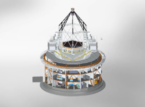
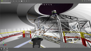
“We are using SOLIDWORKS to support implementation of the Maunakea Spectroscopic Explorer 10-meter-class telescope that will open new possibilities for scientific discovery,” said Greg Green, Mechanical Designer/Instrument Maker, Canada France Hawaii telescope facility. “Our design processes generate a large and growing dataset. The final production version of the telescope will contain over 100,000 parts. We needed technology that can tackle large design projects, and SOLIDWORKS delivers.”

Among its new features, SOLIDWORKS 2019 provides greater design flexibility to quickly interrogate or rapidly make changes to a model through an enhanced Large Design Review capability. It also improves performance view manipulation to scale with higher-end graphics hardware. In addition, SOLIDWORKS 2019 allows teams to communicate outside of the design community by adding markups to parts and assemblies directly using a touch device, storing them with the model, and exporting them as a PDF.

https://www.3dcadworld.com/wp-content/uploads/2018/09/media5.mp4

Another feature is SOLIDWORKS Extended Reality (XR), a new application for publishing CAD scene data created in SOLIDWORKS – including lights, cameras, materials, decals, and motion study animations – and experiencing it in VR, AR and web viewers. Engineers can use SOLIDWORKS XR to improve collaborative internal and external design reviews, sell designs more effectively, train users how to assemble and interact with their products, and boost confidence in designs throughout the product development process.

Dassault Systèmes
www.solidworks.com/product/whats-new


Filed Under: Dassault Systemes, SolidWorks Tagged With: dassaultsystemes

The perfect, unorthodox design

June 15, 2018 By Leslie Langnau Leave a Comment

What if you could create the perfect part unlike anything that exists today? New CAD tools combined with 3D printing can make that happen, makers say.

Jean Thilmany, Senior Editor

No matter what you call the design method, having the computer generate the designs from am engineer’s directions may just be the future. Unorthodox, 3D printed shapes can be found in aerospace now. Soon, such designs will be all around you.

3D printing methods are enabling the development of shapes unproducible by other manufacturing methods. Now, CAD developers are including design tools that take full advantage of the capabilities of 3D printing. These tools are often labeled generative design or topology optimization. They enable engineers to use design software in a new way to best fit design needs.

In April, Autodesk released generative design to subscribers of its Fusion 360 Ultimate product development software. The design concept allows engineers to define design parameters such as material, size, weight, strength, manufacturing methods, and cost constraints–before they begin to design. Then, using artificial-intelligence-based algorithms, the software presents an array of design options that meet the predetermined criteria, says Ravi Akella, director of product management at Autodesk.

“Our effort now is in helping people define the problem they’re trying to solve,” Akella says. “That’s a shift in focus in this industry and makes people have to change the way they have to work.

“The software asks the user preliminary questions. ‘What sorts of materials would you consider for your design? Where does it connect with other things as part of an assembly? What are the loads? What are the pieces of geometry?’” Akella says.

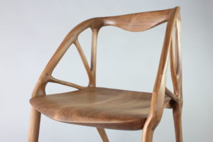
This Elbo chair was designed using Project Dreamcatcher, which was the name Autodesk used for its generative design tool before officially unveiling it this spring.

The software then presents designers and engineers with an array of design options that best meet their requirements. Designers choose the best option. Or, if none of the options meet their needs, they can begin the generative process again, this time offering slightly different inputs.

The computer-generated (“generative”) designs might be unorthodox, new, and unexpected, with geometries that wouldn’t naturally occur to the designer. Yet, no matter how different, if the design is shown to work, it can be created through additive manufacturing,” Akella says.

The method adds value to the present way designers use CAD software, he adds.

“None of these generative questions are asking ‘What is your solution and please start documenting it,” he says. “Without generative design, it’s like engineers were using a piece of paper to explain the problem to themselves. Our job is to get all of that into software.”

He compares generative design with the job of the wine merchant.

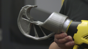
By using Autodesk’s generative design and additive manufacturing technologies, engineers at Stanley Black & Decker shaved more than three pounds off this crimping tool attachment, reducing the weight by more than 60%.

“Someone walks into a wine store and wants a Cabernet Sauvignon,” he says. “To get the best version you go in and say ‘It’s summer and this is what’s on my dinner menu’ and you’re trusting the sommelier to present you with a variety or vintage you’ve never heard of.

“Generative expands your solution options, which sometimes aren’t intuitive,” Akella adds. “Users look at their results and think ‘I never would have thought of it. I’m not sure it’s the right answer but I’m going to check it out further.”

By any other name?

Akella takes issue with what he calls “technologies that masquerade as generative design,” which, he says, include topology optimization, lattice optimization, or parametrics.

“Topology optimization assumes you have a solution you’ve thought of and are making a better version of that solution,” he says. “But generative design expects the user to define the problem they’re trying to solve. Then we use cloud computing and other technologies to present them with a set of solutions that solve their problem in a practical, manufacturable way.”

Generative design produces many valid designs instead of an optimized version of an already-modeled part.

“Optimization usually involves removing excess material without any notion of how something is made or used,” he says.

Generative design also takes manufacturability into account, which reduces an engineer’s need to redesign products after manufacturing weighs in, Akella says.

But developers and executives at other makers of CAD technology may take issue with that depiction of their topology optimization features, which can radically change designs and reduce weight and slash costs, they say.

SolidWorks introduced topology optimization capabilities into its recent release of SolidWorks 2018 Simulation Professional and Simulation Premium.

“We expect the computing platform to anticipate your design goals,” said Gian Paolo Bassi, chief executive officer at Dassault Systèmes SolidWorks, when he spoke at SolidWorks World 2018 in January.

“The era of design and validate is about to end. We are entering the era of optimize and manufacture,” Bassi said.

That means designers specify the aspects of the part they absolutely need, including loads, constraints, boundary conditions, and manufacturing methods. The CAD tool then supplies many versions of a near-optimized part, Bassi says.

Topology optimization can be an additive or subtractive algorithm, meaning it can create parts based on user inputs like loads and boundaries or it can subtract from an existing design by essentially chiseling away at the part, says Robbie Hoyler, a SolidWorks elite application engineer for TPM, an engineering services and design provider in Greenville, S.C.

SolidWorks uses the subtractive method. It creates a meshed part based user-defined loads, constraints and boundary conditions. The software cuts out elements that offer few structural or manufacturing benefits. This process is then repeated until the part meets all constraint requirements, Hoyler says.

The optimized CAD design shows engineers the areas of the part that need to stay and the areas where material can be removed, Hoyler says. He cited an example in which SolidWorks topology optimization reduced the weight of an existing part by 50% without removing areas designers had flagged as necessary.

The part can then be saved as a mesh body in the stereolithography (SL) format for 3D printing or can be retraced as a new SolidWorks part.

Another software package, Inspire, also features generative design and topology optimization tools. It allows users to save the enhanced design as a CAD model (skipping the retracing step). The software is from Altair channel partner solidThinking.

The Inspire’s generative feature is easy to learn and is ideal for small and medium-size businesses with little or no simulation experience, says James Dagg, Altair’s chief technology officer for user experience.

Solid Edge, from Siemens PLM Software, of Plano, Texas, also includes a generative design feature that brings topology optimization to the Solid Edge 3D product development toolkit, according to the company. With the feature, designers define a specific material, design space, permissible loads and constraints and a target weight, and the software automatically computes the geometric solution.

The results can be immediately manufactured on 3D printers, or further recreated as a Solid Edge model for traditional manufacturing. Designers can run multiple weight targets, load cases and constraint scenarios simultaneously, according to Siemens PLM.

Refining the real world
Recently, engineers at automaker General Motors began putting Autodesk’s generative tool to the test to cut weight from GM vehicles. Lighter cars use less fuel, emitting less carbon.
Since 2016, the automaker has launched 14 new vehicle models with a total mass reduction of 350 pounds per vehicle, says Ken Kelzer, GM vice president of global vehicle components and subsystems. The 2019 Chevrolet Silverado, for example, reduced mass by up to 450 pounds as compared to earlier model years.

To further lighten the load, as it were, in May the automaker announced an alliance with Autodesk that will use additive manufacturing and Autodesk’s generative tool to develop future cars and trucks, Kelzer says. The pairing of additive and generative capabilities is a natural for the automaker, Kelzer adds.

GM has used additive technologies for more than 30 years to print 3D parts. The automaker has more than 50 rapid prototype machines that have produced more than 250,000 prototype parts over the last decade, Kelzer says.

And the generative capabilities now included in the Autodesk CAD systems put those printers to work in unique ways, he adds. “When we pair the design technology with manufacturing advances such as 3D printing, our approach to vehicle development is fundamentally different; to co-create with the computer in ways we simply couldn’t have imagined before, Kelzer says.

But the design of formerly unimaginable parts doesn’t mean the engineer lacks ingenuity. Rather, those reduced weight, and perhaps rather odd-looking shapes are the whole point of the generative process, which provides thousands of solutions to one engineering problem, Akella says.

He gives the example of a designer who wants to create a chair. Typically, the designer would start with some geographical representation of the chair humans have taken for granted for centuries; that is, four legs, a seat, and a back. But if the designer were to begin by specifying the amount of weight the chair must support, the materials it will be comprised of, and its cost, “the designer will get hundreds or even thousands of options he or she couldn’t have conceived of on their own,” Akella says.

The nature of the creation process also allows for a part with such complex geometries that it can replace multi-part assemblies. And they can be created with 3D printing, he adds.
The process is also being tested in other industries that design with CAD tools.

For instance, architects at Arup, the building and infrastructure design consultancy in the Netherlands, paired topology optimization and additive manufacturing to redesign a steel node for a unique, public lighting and artistic tensegrity structure.

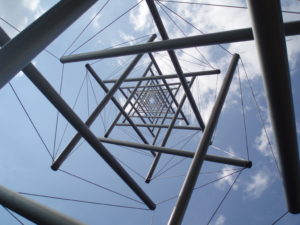
Needle Tower, public art by American sculptor Kenneth Snelson demonstrates the concept of tensegrity. The piece is located outside of the Hirshhorn Museum and Sculpture Garden in Washington, D.C.

Buckminster Fuller coined the term tensegrity to refer to a structure that uses the principle of floating compression, with parts compressed inside a net of continuous tension with cables or tendons delineating the system. Think, of course, of his famous geodesic domes.
Arup designers created their trio of tensegrity structures for a shopping street, the Markstraat, in The Hague. Unveiled in 2013, the “urban chandeliers” integrate street lighting and add an artful element to the area.

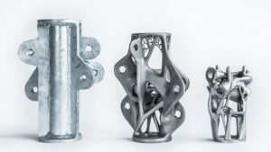
Arup architects designed several variations of the node using conventional and optimization techniques. The third figure, on the right, is the final, lightest shape attained through topology optimization.

The urban chandeliers are beautiful. But they weren’t easy to create, says Salomé Galjaard, an Arup senior designer for the project.

Due to the irregular shape of the structures most of the 1,600 nodes that connected the cables to the struts, were different due to the more than one thousand variations in angle and position of the attached cables, Galjaard told attendees at the 2015 Future Visions symposium in Amsterdam.

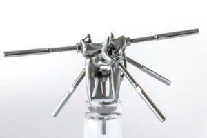
The Arup architectural firm created this 3D-printed, optimized node for a study of nodes used in its urban chandeliers street-lighting project in The Hague.

“This ‘uniqueness’ inspired us to learn more about additive manufacturing,” she says.
Curious as to what optimization could have done for them on a project like the urban chandeliers, Arup designers conducted a study. Both topology optimization and additive manufacture have been little used in the architectural world, so this seemed like an excellent opportunity.

After performing topology optimization, using the Optistruct software from Altair, they found the node they’d modeled traditionally closely resembled the optimized node. And yet, that optimized design reduced the weight the node from 44 pounds to 11 pounds, a 75% drop, without compromising the functional and structural performance of the product, Galjaard says.

Still, the designers spent much more time working with the complex, optimization software than they normally would, and the process could be frustrating, she says.

“Our research illustrates that 3D printing can have a positive impact on the design and production process and the functional product,” she says. “The resulting costs of future construction products could be decreased significantly, whereas architectural freedom will be increased dramatically.”

Generative design and topology optimization can bring the same design freedom and cost reduction to engineering and other types of design of course. Imagine a complex, oddly shaped part that is printed and performs as an assembly. In other words, a part beyond your imagining. That’s the promise of generative design and topology optimization.

Altair
www.altair.com

Autodesk
www.autodesk.com

Dassault Systèmes
www.3ds.com

Siemens PLM Software
www.plm.automation.siemens.com

Filed Under: Autodesk, Featured, Siemens PLM, SolidWorks

Dassault Systèmes announces Global Entrepreneur Program to accompany startups, entrepreneurs and makers

January 9, 2018 By Leslie Langnau Leave a Comment

Dassault Systèmes announced at CES its Global Entrepreneur Program to accelerate the development of breakthrough innovations by startups, entrepreneurs and makers. The program, which leverages Dassault Systèmes’ 3DEXPERIENCE platform, applications, expertise, and community of mentors and services, delivers a full portfolio of tailored solutions and different types of engagement to accompany innovators at every step of their development, from seed to late stage.

More than 1,000 startups, entrepreneurs and makers have already embarked with Dassault Systèmes on digitally developing real-world products and experiences. With the Global Entrepreneur Program, they can use virtual worlds, collaboration, collective intelligence and communities to facilitate innovation, creativity, and to bring ideas to fruition. Innovators can advance projects integrating internet of things and other technologies, design and test products, access online prototyping services using the latest 3D printing methods, and share knowledge and knowhow with a qualified network of professionals, experts and peers from many industries.

Startups have different needs at each phase of their lifecycle. A one-size-fits-all technological, mentoring and marketing approach falls short of providing the diverse levels of support required to help them get products to market faster while, in parallel, addressing business challenges inherent to the startup world such as funding, staffing, IT infrastructure or sales.

The Global Entrepreneur Program’s tracks include design applications and training from SOLIDWORKS for Entrepreneurs for projects focused on mechanical innovation, as well as immersive acceleration in the 3DEXPERIENCE Lab for disruptive startups transforming society that require mentoring, prototyping and marketing support through a network of incubator, accelerator and Fab lab partners across the U.S. and Europe.

The Global Entrepreneur Program also includes the cloud-based 3DEXPERIENCE platform, community management, support and services that bring speed, agility, flexibility, experimentation and collaboration to projects that require more than just a new product engineering activity.

“Entrepreneurs have told us that they value the social community of an incubator above all else, and we listened,” said Frédéric Vacher, Director, Corporate Strategy Innovation, Dassault Systèmes. “Dassault Systèmes loves startups, and our Global Entrepreneur Program supports their innovation processes by providing cloud applications and online communities and services, whatever their industry, product, needs or maturity level. Gone are the days when only large companies had the myriad of skills, resources and capabilities to yield breakthroughs. We are a catalyst and enabler for large companies and startups alike to create concepts, bring virtual and real worlds together, and empower a renaissance of innovation.”

Dassault Systèmes
www.3ds.com

Filed Under: SolidWorks Tagged With: dassaultsystemes

SOLIDWORKS 2018 helps merge design and manufacturing

September 12, 2017 By Leslie Langnau Leave a Comment

Additive manufacturing, the Internet of Things, and other technologies are smashing through the wall that used to separate design and manufacturing. A number of programs being launched this year promise to merge design and manufacturing into one function.

One of those programs is SOLIDWORKS 2018, which includes new tools and enhancements to help engineers get their designs to manufacturing faster. The user interface, for example, lets engineers use a pen or their finger on the touch screen rather than a mouse to design objects. This more natural approach can speed up design.


SOLIDWORKS CAM for CNC machining

CAMWorks, now part of SOLIDWORKS CAM, lets users seamlessly integrate design and manufacturing. It has rules-based machining and automatic feature recognition to streamline and even automate CNC manufacturing operations.

Tolerance Based Machining

Mesh data

Engineers can work with mesh data similar to how they work with surface or solid geometry. Combine, intersect, split, move/copy, cut with surface, and check for interference. In addition, quickly fit surface bodies to regions of mesh models.

More flexibility with 3D Interconnect

Users can seamlessly work with such file formats as ACIS, STEP and IGES, and automatically update designs whenever new files are received. In addition, 3D Interconnect now supports internal file information like custom properties, materials properties and reference axes.

Refined sheet metal design tools

SOLIDWORKS 2018 includes tab and slot features for self-fixturing of parts for welding, a normal cut feature to ensure clearances are included for manufacturing, and tools to easily create or flatten corners that include three bends.

Tab and Slot-sheet metal

Efficient collaboration

Speed up design detailing while also streamlining and automating downstream manufacturing tasks, such as CNC programming and inspection, by importing 3D models along with PMI from all major CAD formats, as well as STEP 242.

Electrical routing

Routing is fast with greater detail. Users can drag and drop in-line connectors and support shrink-wraps and boots. Users can also flatten a route in drawing with support for clips and disjointed routes.

Elec-MultiLevel Terminal

Generative design for better part geometry

The SOLIDWORKS Simulation Topology Study tool can help users automatically optimize the shape of a design based on weight, function, and manufacturing criteria. This features takes into account simulation data and manufacturing constraints.

Topology Study MFG Controls

SOLIDWORKS inspection support for MBD

Users can create inspection documentation directly from 3D models with Production Manufacturing Information, as well as from 2D drawings, PDFs, and TIFFs. SOLIDWORKS Inspection is now integrated with SOLIDWORKS PDM, and supports SOLIDWORKS part and assembly files (*.sldprt, *.sldasm), as well as non-native 3D CAD formats.

MBD default all-over profile tolerance

Project and process management

SOLIDWORKS Manage provides data management, project management, and process management all in one package. It adds powerful project, process, and item management capabilities to SOLIDWORKS PDM Professional.

Design branching and merging

Users can investigate different design approaches without affecting approved files with the new features in SOLIDWORKS PDM. The software also helps to streamline the process of working with external users.

Automated PDF creation for SOLIDWORKS drawings

SOLIDWORKS PDM Standard can automatically create PDFs from SOLIDWORKS drawings through workflow transitions. This feature eliminates the manual creation of PDFs.

Automatic revision table update

SOLIDWORKS PDM manages and automatically updates SOLIDWORKS revision tables.

Cloud-connected SOLIDWORKS

Empower desktop computers with cloud convenience through online licensing. SOLIDWORKS Online Licensing makes using your license on multiple machines effortless. The SOLIDWORKS login moves custom content and settings to any machine on which SOLIDWORKS is installed. The SOLIDWORKS Admin Portal allows easier management of SOLIDWORKS products and services.

Visualize VR

Dassault Systemes
www.3ds.com

Filed Under: Featured, SolidWorks Tagged With: dassaultsystemes

Changes in CAD—what you need to know

June 26, 2017 By Leslie Langnau Leave a Comment

With the March release of Inventor 2018 and AutoCAD 2018, it’s a good time to review several of the recently released major CAD programs. Here’s a look at some of the biggest enhancements and key features of these programs.

Jean Thilmany, Contributing Editor

CAD packages are updated with the same regularity as other major software systems, often annually, with smaller releases to fix bugs or for minor updates happening throughout the year. Sometimes, the annual updates include major enhancements or completely new features. Other times, they include new subscription models, as is the case with Inventor, or offer new ways to access the software, such as through the cloud, which Solid Edge announced with its ST 9 version.

Autodesk Inventor

Here’s what designers will see in the latest version of Autodesk’s flagship mechanical design package:

Large-assembly design has also been made easier in Inventor 2018 from Autodesk. The capability to pan and zoom in on both 3D and 2D designs is improved in this version. The image shows an example of a machine design by equipment-maker Mastenbroek using Inventor.

The big news with the March release of Autodesk Inventor is its subscription-based plan. Users can subscribe for $235 per month. Or, they can choose to pay upfront at $1,890 for one year, $3,590 for two years, and $5,105 for three years.

These type of short-term subscription plans are good for companies that may bring on extra designers, and need more software seats, or during certain times of the year, or for companies that have landed a large project and need more help carrying it out, says Luke Mihelcic, an Autodesk product marketing manager.

Autodesk also has plans to roll out new functions for Inventor every few months rather than within one big, annual update. That is to say, Inventor will see new versions, or major releases, followed by incremental updates that build upon them, Mihelcic adds.

–Model-based definition

This year’s annual update includes model-based design (MBD) tools that users can use to annotate models with product manufacturing information (PMI) like tolerances, dimensions, and manufacturing notes. The tools help projects move from the modeling to the manufacturing stage faster than without the notes, Mihelcic says.

While annotating 3D models already saves time formerly spent creating 2D manufacturing drawings, this new release saves engineers who design in Inventor even more time because they don’t need a special authoring application for 3D annotation. Many engineers who use MBD to annotate models with 3D PMI still have to learn the separate, special application.

–Collaboration tools and ease of use

Inventor has also upped the tool’s interoperability, Mihelcic says. With the 2018 version, users can output 3D PDF files so design information can be shared with others—whether they’re part of the company or not–including manufacturers, customers, suppliers, and marketing managers.

Also in Inventor 2018, the “measure” tool has been simplified and improved to make it easier to use, and bill of materials and parts list sort orders have been made easier to organize because they’re now based on the commands users add themselves, he says.

AutoCAD 2018

The other big system from Autodesk, AutoCAD turns 35 this year. The CAD software and its cousin, AutoCAD LT–which stands for “light” and doesn’t include the full roster of features seen in the main version–also saw a March update, to version 2018, says Heidi Hewett, AutoCAD technical marketing manager.

Autodesk released its AutoCAD 2018 design tool in March.

The newest version is built on a modern code base, which means it runs smoother and faster on current hardware than past versions. In fact, AutoCAD 2018 now supports 4K high-resolution monitors and screens. A 4K display is comprised of 3,840 or higher pixels of horizontal resolution and 2,160 pixels of vertical resolution.

–DWG 2018

The updated CAD system also includes the 2018 DWG (short for drawing) file format, which is the data-file-format AutoCAD uses to create and save designs. This format will improve the efficiency of open and save operations, especially for drawings that contain many annotative objects and viewports, according to Hewett.

This is the first DWG update since 2013. That’s important to know because, while designs created with AutoCAD 2018 will be saved to the 2018 DWG file format, older versions of AutoCAD cannot read the 2018 format. Designers sharing with users on systems that don’t support the 2018 DWG format will need to save their files using an older version of DWG, likely the 2013 version.

–Navigation and Reference Improvements

Version 2018 also introduces tools to fix broken paths for externally referenced files, which helps reduce problems created by broken reference paths and saves the time spent on relinking paths. The upgrade allows users to replace external paths that have one or more missing references with a new path, according to Hewett.

The workflow for creating references is improved with this version. A relative path is automatically assigned to all new, external references.

Users can still choose to assign references as “full path” as was done automatically in previous versions. They can also specify a relative path before saving their drawing. In the past, they couldn’t specify a relative path until they were saving their drawings.

AutoCAD LT won’t see the 3D navigation performance enhancements included in AutoCAD 2018, which Autodesk said offers improvements when using zoom, pan and 3D orbit operations. For example, many larger drawings will no longer degrade as users navigate around the model, the company says. The performance for manipulating 3D models is approaching that of 2D drawings, Hewett adds.

–CAD Viewer update

Autodesk recently re-released the Design Review CAD viewer, which the CAD maker hadn’t updated since the 2013 version. The CAD viewer software lets users view, mark up, print, and track changes to 2D and 3D files for free—even if they don’t own or use AutoCAD. It works with a variety of file formats, including: DWF, DWFx, DWG, and DXF, Adobe PDF, as well as image file types such as.bmp, .jpg, .gif, .png, .tif, .cal and a host of others. The DXF, or drawing exchange format, from Autodesk allows data to be exchanged and read between AutoCAD and other programs.

Solid Edge

This CAD system is Siemens PLM’s main design and engineering offering, with release ST10 soon to come. ST stands for synchronous technology, the method Solid Edge uses for modeling rather than the usual constraint-driven or history-tree modeling. It gives designers the ability to edit models directly rather than making the changes within hierarchical and dependent feature trees, according to Siemens.

Built in data-manage tools included within Solid Edge ST9 are updated with the ST10 release.

–Manage information

Also, new built-in data management tools help manage revisions. In a new “revisions” dialogue box, users can see the entire revision history of a part. They can also comment on any revision in the revision tree and ask whether newer versions of a part are available.

–Sheet metal design and more

Users can design sheet metal parts with Solid Edge ST10 and can edit those parts directly, even if they’re bent. They can also reposition features on the parts, resize them, and change their form without having to go back through the feature tree to correct design errors.

Siemens PLM continues to integrate new capabilities into its Solid Edge CAD system through recent acquisitions including Polarion, for development of software embedded within products, and CD-adapco, for design simulation.

–Additional features

A design manager feature has been added to simplify detecting and replacing duplicate files. After launching the tool, users can see if any of the parts in an assembly have geometric matches with different names and replace them with the preferred part. They’re also able to see tell if a part has a drawing, making it easier to determine the value of one component over another.

The automatic routing path feature in ST10 means users can create routing paths automatically between points within an assembly, part, or sheet-metal design. In earlier versions of the tool, they needed to create routing paths manually. This is a boon for users who design pipelines or create designs that include wiring or hoses, for example, notes a spokesman at Siemens.

Solid Edge ST10 will be the last Solid Edge release to support Windows 7.

SolidWorks

SolidWorks 2017, released earlier this year, offers support for virtual and augmented reality devices such as HTC Vive, Oculus, Google Cardboard, and Samsung devices.

Large assembly capabilities have been improved in SolidWorks 2017, which was released in the fall of 2016 and is the latest version of the system from Dassault Systemes.

This version includes a new user interface, though the change isn’t as dramatic as seen in the previous release. The update now makes the order of configurations sortable, rather than existing only in the order they were created. Also, shortcut menus are streamlined and standardized.

–Interconnection

Users can also open proprietary 3D CAD data in SolidWorks 2017. Systems supported include Creo, CATIA V5, Solid Edge, NX, and Inventor. Associativity is maintained with the original file, meaning updates made within supported systems are automatically reflected in the SolidWorks file.

–Other features

The CAD maker has also expanded capabilities for model-based definition. With this version, users can compare geometry and 3D product and manufacturing information between two revisions, and attached multiple files to a 3D PDF to create technical data packages.

The company’s “visualize boost” feature makes for faster rendering speeds.

New features include a reliability tab that provides access to information such as how the previous session ended and the version of SolidWorks running.

The upgrade also introduces a new feature called “offset on surface,” which allows users to use existing 3D edge and face entities to create new sketches.

Other Updates

 Of course a number of other CAD packages such as TurboCad Deluxe 2017 and NX, also from Siemens PLM, have seen recent updates as well. And we expect to see new features included in future Creo Parametric (formerly Pro/e) versions. In CAD software, as in life, nothing stays the same forever—or even for very long.

Autodesk
Autodesk.com

Siemens PLM
plm.automation.siemens.com

SolidWorks
solidworks.com
Filed Under: 3D CAD Package Tips, Autodesk, Featured, Siemens PLM, SolidWorks

  • Go to page 1
  • Go to page 2
  • Go to page 3
  • Interim pages omitted …
  • Go to page 8
  • Go to Next Page »

Primary Sidebar

3D CAD NEWSLETTERS

MakePartsFast

Follow us on Twitter

Tweets by 3DCADWorld

Footer

3D CAD World logo

DESIGN WORLD NETWORK

Design World Online
The Robot Report
Coupling Tips
Motion Control Tips
Linear Motion Tips
Bearing Tips

3D CAD WORLD

  • Subscribe to our newsletter
  • Advertise with us
  • Contact us
Follow us on Twitter Add us on Facebook Add us on LinkedIn Add us on Instagram Add us on YouTube

3D CAD World - Copyright © 2022 · WTWH Media LLC and its licensors. All rights reserved.
The material on this site may not be reproduced, distributed, transmitted, cached or otherwise used, except with the prior written permission of WTWH Media.

Privacy Policy