• Skip to primary navigation
  • Skip to main content
  • Skip to primary sidebar
  • Skip to footer

3D CAD World

Over 50,000 3D CAD Tips & Tutorials. 3D CAD News by applications and CAD industry news.

  • 3D CAD Package Tips
    • Alibre
    • Autodesk
    • Catia
    • Creo
    • Inventor
    • Onshape
    • Pro/Engineer
    • Siemens PLM
    • SolidWorks
    • SpaceClaim
  • CAD Hardware
  • CAD Industry News
    • Company News
      • Autodesk News
      • Catia News & Events
      • PTC News
      • Siemens PLM & Events
      • SolidWorks News & Events
      • SpaceClaim News
    • Rapid Prototyping
    • Simulation Software
  • Prototype Parts
  • User Forums
    • MCAD Central
    • 3D CAD Forums
    • Engineering Exchange
  • CAD Resources
    • 3D CAD Models
  • Videos

Creo

Updates in CAD focus on better simulation

April 19, 2019 By Leslie Langnau Leave a Comment

While the latest upgrades to major CAD systems don’t make major changes to the way those programs operate, they do include significant updates. Here’s a look at some of the biggest enhancements and key features of these programs.

Jean Thilmany, Senior Editor

CAD packages continue to see regular updates, whether a major release, or the minor updates that happen throughout the year. Some updates include major enhancements or new features, as is the case with NX, which now includes machine learning and artificial intelligence features. The company will quit bringing out yearly NX updates, as the software is now offered on continuous release.

Other popular programs like Creo, Solid Edge, SolidWorks, and Autodesk Fusion 360 have seen changes as well. More than one company has changed the way in which they name the new versions of their software and several boast new or enhanced simulation capabilities.

Here’s a look at the most recent updates.

NX from Siemens PLM

In February, Siemens announced an update to its NX CAD software, which now includes machine learning and artificial intelligence features that, by following users’ patterns over time, come to automatically predict their next steps and anticipate their needs.

The programs do this by monitoring the actions of the user and following their success and failures. In that way, the features determine how to serve up the right NX commands and also modify the user interface accordingly, says Bob Haubrock, senior vice President, product engineering software at Siemens PLM Software.

Machine learning is increasingly used in the product design process because it has the power to process, analyze, and learn from large volumes of data, he adds. In this way, designers can more efficiently use software to increase productivity. The ability to automatically adapt the user interface to meet the needs of different types of users in various departments can increase CAD adoption rates at a company, continues Haubrock.

In another recent change, Siemens PLM Software began delivering NX using a continuous release model. This means the software updates are produced in short cycles and are released when needed, at any time.

The model gives NX users faster access to new enhancements and quality improvements, while reducing the efforts needed to effectively deploy NX, Haubrock says. “With automatic updates, customers do not have to search for updates online and will not miss critical fixes. The NX Update mechanism will automatically notify and install important updates as they become available.”

With continuous release, users can turn on “automatic updates” within their system to ensure they always receive the updates. The approach helps reduce the cost, time, and risk of delivering changes by allowing for more incremental updates to applications.

Thus, NX will no longer be identified by a release number and will only be referred to as NX. In other words, there will be no NX13.

The CADmaker says it’s the first major CAD, CAM, and analysis vendor to deliver its products in this way.
The company says the new approach will enable Siemens’ NX users to:
–Receive enhancements faster to help boost productivity
–Have a consistent schedule for updates
–Better plan for the adoption of new technologies
–Reduce deployment costs

Creo from PTC

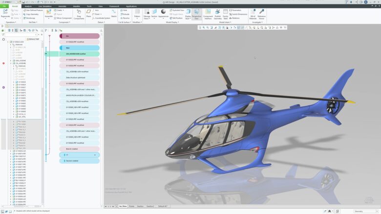
In February PTC released Creo Simulation Live, which allows engineers to perform simulation in real time on their parametric models because ANSYS simulation capabilities have been integrated with the Creo CAD tool.

Creo Simulation Live, from PTC, lets engineers perform simulation in real time on their parametric models because ANSYS simulation capabilities have been integrated with the Creo CAD tool.

“Every time you make a change in your model, you’ll see the consequences instantaneously in the modeling environment,” says Brian Thompson, PTC senior vice president, CAD segment.

“The goal is to remove the barrier between the CAD and CAE world,” says Andrew Leedy, a PTC applications engineer. “This is targeted toward the engineer or designer rather than the analyst.”

The simulation software runs linear, structural, thermal, and modal analyses. The solver uses GPU rather than CPU for instantaneous analysis, Leedy adds. “So as soon as you make changes to the model it updates the graphics that drive the simulation.

The capability to simulate and design simultaneously helps engineers understand the implications of what they’re making, he adds.

The integrated tool also eliminates the need for the engineer to mesh the model before running a simulation and does away with the post-processing step.

The integrated simulation software from ANSYS is called Discovery Live.

“Engineers can ask ‘What if I add this hole, what will it do to the model?’” he said. “This works on top of the model, it works directly within the environment an engineer is used to.”

The CAD software does require a graphics card that supports the ANSYS tool.

Solid Edge from Siemens PLM

Solid Edge 2019 brings a new naming convention to the tool, which will now be referred to by the year in which it is released. This makes it easier for engineers to identify the release they’re using as well and to identify the products within the Solid Edge portfolio, says Ben Weisenberg, applications engineer at product lifecycle management company Prolim. Weisenberg frequently details Solid Edge updates to the CADmaker’s user community.

Solid Edge 2019, from Siemens PLM, makes it easier for engineers to identify the products within the Solid Edge portfolio. The most significant updates for mechanical designers are tools that allow engineers to model and simulate the entire production process along with the final product.

The most significant updates for mechanical designers are tools that allow engineers to model and simulate the entire production process along with the final product, Weisenberg says.

These include the convergent modeling tools that designers can use to integrate mesh models directly into their workflows. They can use these tools for the milling, casting, and molding of generative designs and 3D printed designs.

Manufacturing constraints allow engineers to optimize the weight and strength requirements of their model. A new design-for-cost feature shows the anticipated cost of the part, to help keep product development on track and within budget.

Updated simulation capabilities include:
–Enhanced structural and thermal simulation, including transient heat transfer.
–Time-based history analysis enables simulation of thermal and cooling performance.
–Free surface flow simulation, lighting and radiation capabilities allow digital “what if” analysis.
–The ability to display simulation results on geometry faces to help engineers make more informed judgments about the model.

SolidWorks from Dassault Systèmes

New features to the program, released in September 2018, let product development teams better manage large amounts of data and capture a more complete digital representation of a design. The program also offers new technologies and workflows that improve collaboration and enable immersive, interactive experiences during design and engineering.

SolidWorks 2019, from Dassault Systèmes, is powered by the company’s 3DExperience platform, which runs the CAD, simulation, and other tools on which designers and engineers rely. Those applications on the 3DExperience platform are tailored to SolidWorks users and mid-market companies.

Other new features include the capability for engineers to interrogate or rapidly make changes to a model through an enhanced large design review capability. Another upgrade gives teams a way to communicate with others not involved in design. With this feature, viewers of the CAD design can add markups to parts and assemblies and then export the marked-up designs as a PDF.

The most recent update from Dassault Systèmes involves the Works portfolio, which will bring applications like SolidWorks together with business solutions like a company’s enterprise resource planning (ERP) system. Typically, ERP systems track all pertinent companywide business processes, including accounting, supply chain, and human resources.

When parent company Dassault Systèmes launched SolidWorks 2019, executives stated that the CAD tool was “powered” by the company’s 3DExperience platform, which runs the CAD, simulation, and other tools on which designers and engineers rely.

Those applications continue to run on the company’s 3DExperience platform and are tailored to SolidWorks users and mid-market companies. They have been folded in the 3DExperienceWorks portfolio.

SolidWorks executives term the new portfolio a “business experience platform.” It provides software solutions for every organization within a company—from design to enterprise resource management, says Bernard Charlès, vice chairman and chief executive officer for Dassault Systèmes. “It’s a way for mid-market companies to tie all processes together, from design to manufacturing.”

Use of the applications across the platform should improve collaboration, manufacturing efficiency, and business agility, he added. Companies can accomplish their work using one cohesive digital innovation environment instead of using a complex series of point solutions that requires jumping between applications and interfaces, Charlès, says.

The software on the platform includes SolidWorks, analysis, simulation, manufacturing, and ERP applications. It is available on-premise and in the public or private cloud. The platform connects data and streamlines business and design processes by providing dashboard templates, managed services, access to industry-focused communities and user groups, and applications specific to a variety of job roles, Charlès says.

Autodesk

Like other CADmakers Autodesk has consolidated its design, simulation, and other computer-aided engineering capabilities in one product, Fusion 360, which is available as a cloud-based product. The product unifies design, engineering, and manufacturing into a single platform, according to Autodesk.

Fusion is a 3D modeling took that includes simulation, visualization, rendering, CAM, and other functions within a single interface. It also includes a 3D animation tool and 2D drawing tools. The product runs on both Windows and Macintosh systems.

In March, updates to that product included the capability to know when a teammate is working on your design at the same time to avoid doing work that will be over-ridden by another designer. When someone is working on the same design, an icon is displayed in the toolbar. By using a mouse to hover over the icon, a designer can see who is working on the same design. If one person makes a change to the design and saves it, the icon in the toolbar will change, letting the designer know that the design now has a newer version.

The toolbar has been updated to include quick access tools and documents tabs that line up with one another for more space on the design desktop.

Also new is a hole-tap tool called taper tapped, which allows designers to choose among a variety of thread types.

Autodesk also maintains its AutoCAD and Inventor CAD tools with no plans to immediately discontinue those products. Those two CAD systems usually see a new release in March of each year; though as of press time Autodesk hasn’t announced 2020 versions of AutoCAD or Inventor.

At Autodesk University in November 2018, Greg Fallon, vice president of business strategy at Autodesk, did announce updates to a collection of tools that work inside Inventor as well as a suite of specialized toolsets now available with AutoCAD.

Two years previously at Autodesk University 2016, company officials said they expect to maintain Inventor for another five to ten years and plan to continue updating it and enhancing functions. The Inventor emphasis will continue to be on industrial machinery design, officials said at that time.

While Inventor may be phased out in favor of Fusion 360, this has not been explicitly stated by Autodesk executives.

As ever, there are too many CAD packages to include in a single roundup. Other applications include IronCAD, TurboCAD, OnShape, Catia, and KeyCreator. All these will include new and updated features in future updates.

As designers and engineers know, when it comes to CAD software, the key phrase is, constant evolution.

Ansys
www.ansys.com

Autodesk
www.autodesk.com

Dassault Systèmes
www.3ds.com

PTC
www.ptc.com

Siemens PLM
www.plm.automation.siemens.com

Filed Under: Autodesk, Creo, Siemens PLM, Software, SolidWorks

PTC announces Creo 5.0 with additive manufacturing and topology optimization features

March 19, 2018 By Leslie Langnau Leave a Comment

PTC (NASDAQ: PTC) announced Creo 5.0, the latest release of its Creo 3D computer-aided design (CAD) software that enables users to go from concept to manufacturing in one design environment. Creo 5.0 introduces five new capabilities for product design and offers new productivity enhancements.

With Creo 5.0, concepts can be transformed into smart, connected products, bridging the physical and digital worlds with augmented reality (AR) capabilities in every seat. Creo 5.0 introduces capabilities in the areas of topology optimization, additive and subtractive manufacturing, computational fluid dynamics, and CAM.

“PTC is on the leading edge of some of the hottest technologies today with the Internet of Things (IoT) and augmented reality (AR), but it has not forgotten its roots in CAD, instead transforming this business by infusing its leading Creo software with new technologies and capabilities,” said John Mackrell, chairman, CIMdata. “Creo 5.0 is yet another example of PTC’s continued innovation and ability to meet customer needs.”

Topology optimization
The physical design of products is often limited by existing designs and practices. Creo Topology Optimization Extension automatically creates optimized designs based on a defined set of objectives and constraints, unfettered by existing designs and thought processes. This helps users save time and accelerate innovation by enabling creation of optimized and efficient parts.

Additive and subtractive manufacturing
Creo enables users to design, optimize, print check, and additively manufacture parts without the need for multiple pieces of software. By streamlining the process and reducing the need to recreate models, more time can be spent focused on what is really important, the design. Creo 5.0 introduces the Creo Additive Manufacturing Plus Extension for Materialise, which extends these capabilities to metal parts, allowing customers to print production-grade parts directly from Creo. Additionally, the extension allows users to connect to the Materialise online library of print drivers and profiles.

The Creo Mold Machining extension provides dedicated high-speed machining capabilities for molds, dies, electrodes, and prototype machining. Creo 5.0 supports 3-axis and 3+2 positioning machining.

Creo Flow Analysis
The Creo Flow Analysis extension is a computational fluid dynamics (CFD) solution, which allows designers, engineers, and analysts to simulate fluid flow issues directly within Creo. The seamless workflow between CAD and CFD allows users to integrate analysis early and often to understand product function and performance. The software is purpose-built specifically for the design engineer and is easy-to-use, directly integrated within Creo, highly accurate, and provides fast results.

Productivity improvements
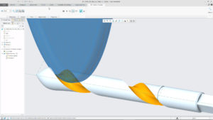
Creo 5.0 also includes key productivity improvements for the fast-changing world of product design, such as an improved user interface, geometry creation with sketch regions, and volume helical sweeps. Other enhancements include improvements to surfacing, sheet metal design, and the application of draft features involving rounds. Users can also now design in Creo while maintaining perspective display mode.

The Creo Collaboration Extension for Autodesk Inventor enables organizations to consolidate onto a single CAD system, enabling them to reduce the cost and effort associated with maintaining multiple systems and integrations, and enabling better data reuse and resource sharing. Creo 5.0 will now support bi-directional exchange of both parts and assemblies with Autodesk Inventor.

“Product design is fundamentally changing, and Creo continues to evolve to meet the needs of our customers. With Creo, companies can go from the earliest phases of design to a smart, connected product,” said Brian Thompson, senior vice president, CAD Segment, PTC. “Improved functionality and new capabilities, like additive manufacturing, set Creo apart, and give companies a true competitive edge all the way from concept to manufacturing.”

PTC
www.ptc.com/en/products/cad/creo/whats-new

Filed Under: Creo Tagged With: PTC Creo

GRANTA and PTC team up to provide materials data in CREO 4.0

December 7, 2016 By Leslie Langnau Leave a Comment

Granta Design  announced that sample materials property data from Granta, the materials information technology leader, will be available to users of the new Creo® 4.0 3D CAD software from PTC. This addition provides fast, easy access to property data covering 117 sample materials, including commonly-used metals, plastics, composites, and ceramics. Creo users can browse the data and apply it to parts in their Creo model. The data includes density, thus supporting weight roll-up calculations, and a set of mechanical and thermal properties, which can enable accurate analysis and smarter design decisions. The data is a sample from Granta’s comprehensive materials data library.

MI:Materials Gateway for Creo – an upgrade option that enables Creo users to access their corporate materials database within Creo.

At the heart of Granta’s materials data library is MaterialUniverse, compiled and maintained by Granta and covering over 3,800 types of engineering material. Each record provides a complete, consistent set of 80+ mechanical, thermal, electrical, physical, environmental, and economic properties. MaterialUniverse data is ideal for exploring the material landscape, for example, during initial material selection or in early-stage design. Other data sets in the library include authoritative handbook and design data, supplier data, standards, test data, and simulation input data. Compiled by Granta or its partner organizations, these describe tens of thousands of metals, plastics, composites, and more, enabling users to ‘drill down’ into detailed grade-specific data.

The data now available within Creo is from a representative sample of MaterialUniverse records. Creo users wishing to access more of the library have two options. They can purchase the CES Selector™ PC software, from which property data can be exported in Creo format. Or, if their company uses the industry-standard GRANTA MI™ system to manage its proprietary materials information, they can install and use GRANTA MI:Materials Gateway™ for Creo. This app runs within Creo and provides direct access not only to the Granta data library, but also to any corporate materials data to which the user has access rights.

Granta Design Ltd
www.grantadesign.com


Filed Under: Creo, News

PTC Announces Creo 4.0 for Smarter Design

November 18, 2016 By Leslie Langnau Leave a Comment

PTC (NASDAQ: PTC)  announced the release of the latest version of its Creo 4.0 3D CAD software. Creo 4.0 introduces new capabilities for Internet of Things (IoT), additive manufacturing, augmented reality, and model-based definition (MBD). Creo 4.0 aids smarter design with an array of core modeling enhancements and new functions.

creo-4-0-variable-lattice-copy

With this latest release of Creo, product designers can design smart, connected products and capitalize on new technologies, such as additive manufacturing and augmented reality.

Key enhancements include:

Smart Connected Product Design

For the IoT, Creo 4.0 provides the ability to pull real-world information into the design process. It enables a design for connectivity strategy where developers proactively design products with custom data streams by integrating sensors into the design process.

Said Chad Jackson, Lifecycle Insights, “Connecting Creo’s 3D model with ThingWorx’s sensor model is key, as it allows organizations to virtually prototype sensor placement and emulate data streams without having to build anything physical.”

Additive Manufacturing
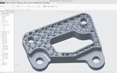
Creo 4.0 removes barriers to the efficient design of production parts built with additive manufacturing techniques. It delivers “design for additive manufacturing,” enabling designers to design, optimize, validate, and run a print-check in a single environment. With the ability to create parametrically controlled lattice structures, it helps designers optimize models to meet multiple design objectives or constraints.

Augmented Reality

Creo 4.0 allows for more engaging and informative visual experiences of designs by bringing the digital product into the physical world. Designers can seamlessly reuse CAD data to easily create engaging and informative visual augmented reality experiences of a design with a realistic sense of size, scale, and context.

 Model Based Definition

Creo 4.0 enables designers to implement MBD and increase efficiency in product development by reducing dependency on 2D drawings. Designers can reduce errors that result from incorrect, incomplete, or misinterpreted information by guiding and educating designers in the proper application of Geometric Dimensioning and Tolerance (GD&T) information. Creo 4.0 also validates that the GD&T is captured in the 3D CAD model in a fully semantic way, that the model is compliant with ASME and ISO standards, and that it constrains model geometry to enable efficient and error-free downstream use in manufacturing and inspection.

“Realizing the potential of the IoT is not just about getting more product usage data, it means you can use, refine, and analyze that data to design better and smarter,” said Brian Thompson, senior vice president, CAD segment, PTC. “Creo 4.0 helps designers replace assumptions in the design process with real-world data to make better product design decisions, and along with model-based definition, give designers a more complete digital definition of a product. The enhancements in Creo 4.0 not only enable designers to increase productivity, but also help designers leverage the IoT to support their digital engineering journey.”

PTC
www.ptc.com

Filed Under: Creo, News, PTC News Tagged With: PTC

GrabCAD Announces Integration with PTC Creo and Workbench Summer 2014 Release

June 18, 2014 By Barb Schmitz Leave a Comment

It appears the folks at GrabCAD have been quite busy. The Cambridge-based startup is making two significant announcements today: the integration of its Workbench cloud-based file management platform with PTC Creo CAD software and the release of Workbench Summer 2014.

Since PTC Live Global was just held this week in Boston, we’ll start with that one. The integration of Workbench with Creo means that users will now have a host of new capabilities that are available only to PTC Creo users. These new capabilities include:
● The ability to view native models
● The ability to view Creo drawings and other proprietary Creo documents
● The ability to interact with assembly information, such as family table instances

In addition, the processing power for all of the above actions will be provided by the GrabCAD cloud platform, freeing up the user’s desktop for other tasks. GrabCAD and PTC will roll out these new capabilities over the next several months to both new and existing PTC Creo and Workbench users.

“PTC Creo is the CAD tool of choice for many of the companies that use Workbench, whose users appreciate the ability to access an integrated set of design, simulation and manufacturing tools in one suite,” said Hardi Meybaum, founder and CEO of GrabCAD. “We’re excited that this integration with PTC Creo will make it even easier for these users to keep track of CAD files and bring others into their design process quickly and easily.”

GrabCAD Workbench is a cloud-based file management platform that makes it easier for users to manage and share CAD files.

Summer Release 2014

The company also announced that July 1st it will ship its Summer Release of GrabCAD Workbench. Already boasting CAD file management and external collaboration features, Workbench makes it easy for mid-sized companies to better deal with CAD file management.

The Summer Release’s new capabilities include:
● Flexible search capabilities. Search on metadata such as date, type, author, revision, version, and custom file properties
● “Whereused” reports. Shows where a part is used in other assemblies
● Assembly BOM Views. Display, filter, and export the parts list of any CAD assembly
● Configuration and family table support. View different configurations and families of parts and assemblies from major CAD systems

Many engineering organizations rely on more than one CAD provider, so Workbench is designed to support them all. This “multiCAD” approach is supported by a number of new CAD-specific enhancements:
● SolidWorks. Intelligent notifications alert users of document changes such as when a file is locked or affected by changes to another document
● Creo. Automatically detects the latest Creo file for upload; view native parts, assemblies, and drawings
● Autodesk. Support for 3D DWG

In addition to these new features, GrabCAD has made more than 100 enhancements to existing features over the last six months, including:
● Revision control. Links assembly revision to part revision
● Version control and backup. Restores deleted files or restore to a point in time
● File locking. Lock status now available inside SolidWorks Workbench add-in

Learn more about GrabCAD Workbench by clicking here.

Barb Schmitz

Filed Under: Creo, Inventor, News, SolidWorks Tagged With: Collaboration, file management

PTC Releases Creo Elements/Direct v19.0

June 18, 2014 By Barb Schmitz Leave a Comment

Another announcement made at this year’s PTC Live Global event was the release of PTC Creo Elements/Direct 19.0, direct modeling software that now includes productivity enhancements in modeling, drafting, collaboration and data management. As mentioned in the Creo 3.0 blog, the company also unveiled new technology it’s calling Unite technology that better supports multi-CAD environments.

Collaboration seems to remain a tricky task for distributed design teams juggling format in multiple CAD file formats. The Unite technology will enable users to open native CAD files created in other popular CAD formats, and then save, edit and share that data with others. The response from users attending the event was unanimously favorable.

“The new import capabilities in PTC Creo Elements/Direct 19.0, formerly known as CoCreate, will allow us to collaborate more effectively with companies using different CAD tools,” said Nobuaki Sugimoto, mechanical designer, Icom, Inc.

PTC Creo Elements/Direct 19 now offers support for multi-CAD environments, via Unite technology

Enhancements to Creo Elements/Direct include:

* Support for Multi-CAD Collaboration. Support for direct import of SOLIDWORKS and Autodesk Inventor data enables teams to quickly and easily incorporate design information without the need for additional software. Upward compatibility with PTC Creo is also significantly enhanced.

* Optimized Design Workflows. Higher productivity is enabled through optimized design workflows for a variety of regularly used features, and the introduction of template-based drawing creation significantly reduces redundant effort by enabling the re-use of existing drawings as a starting point.

* New Concept Design Capabilities. Concept design is made easier with the introduction of new 2D and 3D tools including support for the use of 2D images in concept development, a palette of pre-defined 2D shapes and new curve creation commands.

* New Sheet Metal Capabilities. New capabilities in the sheet metal module allow the creation of fully valid, un-foldable sheet metal parts that represent a transition between two parallel profiles.

* Scalable Data Management. Through core infrastructural improvements, PTC Creo Elements/Direct Model Manager delivers greater scalability for large deployments.

For a more extensive list of new enhancements to Creo Elements/Direct 19.0, click here.

Filed Under: Creo, News, PTC/CoCreate Blogs Tagged With: concept design, data management, Direct Modeling, sheet metal design

Creo 3.0 Announced at PTC Live Global

June 17, 2014 By Barb Schmitz Leave a Comment

Amid the excitement of users, partners, analysts and members of the press–along with hundreds of Boston-based employees, PTC announces the release of Creo 3.0. Among the most impressive of its enhancements and feature upgrades is what PTC has dubbed Unite Technology.

Designed to help its customers overcome the struggles of dealing with CAD data in multiple formats, Unite Technology provides users with an easier way to use multi-CAD data in Creo. The new release also offers new integrated concept design tools that make it easy and fast to capture concept ideas–both good and bad–for future use and to reuse concept designs in the detailed design process.

Other productivity enhancements within the release will reportedly add to customers’ ability to focus on higher levels of innovation and product quality.

Unite Technology.

Unite technology enables CAD data of varying formats to be used directly in Creo apps, including Creo Parametric, Creo Direct, Creo Simulate, and Creo Options Modeler apps. This ability should go a long ways towards customers gaining efficiencies from consolidating multiple CAD systems onto PTC Creo.

The Unite Technology should also facilitate design collaboration with partners who use competing CAD tools by allowing users to easily reuse existing CAD data as is, in its current format, with no need for a costly upfront migration. It also enables users to convert existing legacy data to PTC Creo easily, on demand, and only when modifications are actually needed.

There is no need to convert entire assemblies to modify individual parts, users simply convert parts as changes are required.

Creo’s Unite Technology makes collaboration easier because it enables design participants to natively open SolidWorks, CATIA and NX files directly in PTC Creo without the need for additional software or any error-prone translation or conversion process. Users can also import SolidWorks, CATIA, NX, Solid Edge and Autodesk Inventor files into Creo without the need for additional software.

This new functionality also enables higher levels of concurrent engineering between the product development teams and suppliers/partners/customers by allowing designers to quickly and easily incorporate native CAD geometry created in other systems earlier in the process, create design intent across CAD formats and, as new versions of the non-PTC Creo data are updated in the assembly, ensure that any design intent build between the original part and the PTC Creo parts are protected when the part is updated.

Unite also helps promote the reuse and sharing of data and eliminates the need to manage many secondary formats, and significantly reduces the need to export data in neutral formats. Data can be shared in customer/supplier’s native format, eliminating the step of using neutral file formats.

The new release of Creo 3.0 will enable customers to work and consolidate data from any CAD source.

New concept design tools

PTC Creo 3.0 has also made some improvements in the area of concept design. These new tools and features include:
* Align Freestyle design functionality (part of PTC Creo Parametric) enables designers to create and drive freeform designs parametrically, combining organic geometry creation and modification with associative parametric design intent.

* Greater scalability and richer tools in PTC Creo Layout to support 2D concept engineering activities with seamless re-use in the 3D parametric environment

*A more powerful and easier-to use 3D direct modeling app (PTC Creo Direct) for quickly creating concept designs that are fully reusable in PTC Creo Parametric

* PTC Creo Design Exploration Extension provides a dedicated environment in PTC Creo Parametric for developing design alternatives, investigating modeling approaches and safely understanding the consequences of design changes.

Other new features include a completely redesigned Help system that uses Google search functionality, integrated hardware libraries, automated fastener assembly workflows, MathCAD integration (shipped free with Creo Parametric), a new 3D Thickness Check for injection-molded products, new analysis tools, photorealistic rendering courtesy of KeyShot, and improvements to the Creo Flexible Modeling Extension and ECAD Collaboration Extension.

We really just scratched the surface of all the new bells and whistles in Creo 3.0. For more information on Creo 3.0, check out this page. Creo 3.0 with Unite Technology will ship mid-July.

Barb Schmitz

Filed Under: Creo, News, PTC/CoCreate Blogs Tagged With: analysis, cad, Collaboration, multi-CAD

Luxion Releases KeyShot 5 Rendering Software

June 2, 2014 By Barb Schmitz Leave a Comment

Rendering software is increasingly being put to use by design engineers to create downstream product collateral used to support, maintain and sell products–often before the product even exists in physical form. Rendered 3D models are also created and used early in the design process to speed the process of obtaining customer or management approval.

Rendering vendors are working hard to make it easier for users to import 3D models and have incorporated features specific to the the way engineers work. After all, the engineering workflow is quite different from those of users in the arts and entertainment markets.

Read more on rendering software in the Design World feature A Picture’s Worth a Thousand Words: Why Rendering is Increasingly Important to Product Development.

KeyShot 5 for rendering and animation

Luxion has recently released the latest version of its KeyShot rendering software, touted to be the first real-time ray tracing and global illumination software. By providing faster rendering speed and capabilities, users can create images, animations and interactive visuals throughout the product development process quickly and easily.

KeyShot 5 introduces enhanced usability and pro-level features that allow engineers, designers and 3D professionals to make their workflow more efficient and take their visuals to the next level. The software’s new streamlined interface offers new features for a faster rendering and animation workflow, the ability to work with materials faster and more powerful new animation features.

New features in KeyShot rendering software enable engineers to make their workflow more efficient and take their visual assets to the next level.

What’s new?

KeyShot Cloud. Online library where users can download new resources and share their own custom assets. Opening the KeyShot Cloud enables easy drag-and-drop downloading of new resources into their local KeyShot Library, and quick search features and filters to find the perfect resources for a scene. All resources remain on a user’s computer with a copy of the resource uploaded to the KeyShot Cloud and no scene or personal info stored online. The KeyShot Cloud is accessible directly from inside KeyShot and online here.

NURBS Ray-tracing. NURBS ray-tracing delivers more accurate geometry with smoother edges. This new import feature gives users the option to import and render NURBS geometry from their favorite 3D modeling application. The advantage is crisper visuals and smaller file sizes over data imported as triangle that can display edges and gaps on close detail shots. NURBS import is currently available for all geometry formats, including Creo, CATIA, Inventor, NX, Rhino, SolidWorks, Solid Edge, STEP, IGES, Parasolid and ALIAS. Available with KeyShot Pro versions.

Instancing. Instancing allows users to duplicate parts in KeyShot and on import without increasing file size. Instancing of parts is available within KeyShot as a Pattern tool and completely automated in select KeyShot plugins. All instances can be treated separately for quick appearance studies or linked to apply materials quickly, but will all update when LiveLinking or update geometry is used.

Fade Animation. The new Fade animation allows users to quickly apply an animation that fades parts from one opacity level to another. Through KeyShot Animation users add individual transforms that add animations with a click of a button instead of managing keyframes. Just as simple, Fade animations can be applied while adjusting the opacity of parts and groups on-the-fly which allows users to see the update in real-time as animations are created. Available with the KeyShot Animation Add-on.

Sun & Sky System. KeyShot 5 introduces a new Sun & Sky system for automatic creation of physically accurate geographic lighting. Preset resolutions and locations together with day selection, time and turbidity sliders allow the creation of unlimited daylight scenarios. Custom Sun & Sky environments can be created by users as well and combined with other lighting options available in the KeyShot HDRI Editor. Available with KeyShot Pro versions.

KeyShot 5 is available now. Pricing starts at $995. The entire list of features in KeyShot 5 can be seen and downloaded in a What’s New guide that includes information on how each feature works.

Barb Schmitz

Filed Under: Creo, General Blogs, Inventor, Rhino, Siemens PLM, SolidWorks Tagged With: animation, rendering

Debating the Most Efficient Way to Go from Concept to Documentation

April 15, 2014 By Barb Schmitz Leave a Comment

The conceptual phase of design is the only one within the product development window that must be inherently fluid, and in a sense, should be done in a leisurely manner. What, you ask? The word “leisure” is probably not used often when it comes to designing products, right? OK, let me explain.

In order to fully evaluate a suitable number of potential design concepts, engineers and designers must have the luxury of time. After all, how can you determine an optimum solution until you’ve discounted an adequate number of bogus ones? Unfortunately, not many of them get that time.

According to a conceptual design study conducted by PTC, 92% of respondents felt that their product development process would benefit tremendously from the ability to evaluate more concept ideas before moving forward into detailed design and documentation. Another 61% said that the concept design process is often cut short to due schedule constraints.

Time, after all, is critical to meeting design production schedules and shipping products on time. It’s the underlying reality of all those involved with product development.

This concept design for Yamaha was created by a Alberto Agnari. It included concept boards, sketches and traditional and digital renderings.

Which route to take: direct or feature-based?

Once a concept design has been approved and moved forward, time is of the essence. During our “The Pros and Cons of 3D Modeling Paradigms” webinar, one of the questions posed to our panel of speakers was in regards to what modeling paradigm is best in terms of time efficiency when moving from the concept stage to the documentation state, keeping in mind that a good percentage of the dimensions can be automatically generated within the history-based model. The answers were surprising and I thought worth sharing.

Dan Staples, vice president, Solid Edge Product Development, Siemens PLM Software

In a history-based system the dimensions are in the sketches and then those are retrieved into the drawing. In a direct modeling system, or at least in Solid Edge, the dimensions take the form of what we call PMI (product manufacturing information) or the 3D dimensions that are on the faces of the model instead of in the sketches. That doesn’t change the ability to retreat those into the drawing. The fact is that they’re on the faces instead of the sketches, same thing in terms of ability to retrieve those that are in the drawing and use them.

Brian Thompson, vice president of Creo Product Management, PTC

Yeah, I think if you have good workflows for creating or showing those dimensions in the 2D context, it could be similar in terms of efficiency to do either. I don’t see one modeling paradigm strongly standing out. There’s good efficient workflows for creating dimensions on models that have no underlying sketches, and there’s good workflows for showing them on models that do. As Dan and I have said, dimensions in the direct modeling environment can, in fact, still drive geometry if the user tells the system that’s what he wants.

You can still even get that behavior. Maybe not to the level you would get with a large feature-based, history-based parametric model, but you could still get that behavior. There may be some circumstances where one is slightly better than the other, but I’d say it’s fairly close in terms of efficiency to create that documentation. Would you agree Dan?

Dan Staples

I would actually say it’s somewhat more efficient. One of the constraints we forget about is that when you build up a history-based model, you build it up sketch by sketch by sketch. That’s not necessarily a natural way to dimension the part. In fact, it’s pretty bad practice in terms of a dimensioning scheme because you tend to have a lot more dimensional stack ups than you would like. Whereas if you’re in a direct modeler, you can put in dimension between two faces on the model that are far from each and there’s 50 features in between, and so you can actually have a much more natural dimensioning scheme that’s more immediately usable in the drawing when you see direct models in my opinion.

Brian Thompson

Yeah, I think we’ll agree there that bad modeling technique and your history-based parametric modeling will make it even harder in the drawing to do that. If you got a good, well-done history tree then maybe it’s not as hard but it’s a good point.

The bottom line

Though it’s not easy to sum up all the good points here, its clear the most time-efficient way to move your designs from concept to documentation is to use best practices when it comes to how you model your products and good dimensioning workflows. In other words, the use of good modeling techniques will always get you from Point A to Point B faster, whether you’re working in a direct modeling or feature-based modeling 3D CAD system.

If you missed the “Pros and Cons of 3D Modeling Paradigms” webinar, you can watch it in its entirety here.

Barb Schmitz

Filed Under: 3D CAD Package Tips, Creo, Siemens PLM Tagged With: concept design, Creo, documentation, Solid Edge

The Role of Associativity in Direct Modeling

April 1, 2014 By Barb Schmitz Leave a Comment

When designers and engineers think about design associativity, they often think about history-based 3D modeling systems. CAD software that deploys a history-based approach to modeling requires engineers to anticipate and define feature constraints, relations and dependencies, which ensures that any design change will update all related downstream geometry. That’s design associativity.

Though they require a lot more work, thought and pre-planning on the part of the user, history-based modeling systems provide users with a methodical, orderly and powerfully automated way to create models. The problems arise, however, when changes have to be made, a rather common occurrence at all stages of development. Even small design changes cause a domino effect so users must carefully consider the impact a change will have to associated parts.

Design associativity is not exclusive to history-based 3D modeling approaches. Image courtesy of PTC.

Is there associativity in direct modeling?

During The Pros and Cons of 3D Modeling Paradigms webinar, one of the questions asked of our panel of experts was what is the role or definition of associativity in direct modeling? Our panelists each brought a unique perspective to that question, which I thought was worthy of sharing.

Dan Staples, vice president of Solid Edge Product Development, Siemens PLM Software

To me the word associativity with parametrics is the notion that changing one thing changes other things that are associative. Things can be related to one another and things can be dimensionally driven and, therefore, association between the dimension and the faces. The key difference is that it doesn’t cause a linear regeneration of the treetop to bottom. That expensive piece is you edit the first feature and you pay for all subsequent thousand features.

That’s not true in a direct modeling system. However, there is the notion of associativity, meaning that things can happen. Dimensions are edited and faces moved, or Face A is associated with Face B and, therefore, it should move also. That’s associativity by my definition, and it’s perfectly valid in a direct modeling system.

Chad Jackson, principal analyst, Lifecycle Insights

There is probably a finer point here, which is there’s design associativity and there’s deliverable associativity. You might want to have design intent because of intent ripple has a change ripple across multiple parts in the same assembly. You might want to have that. Obviously when you change a part, you want the drawing to update and you want a service assembly animation to update. I think in both of those cases, neither are really limited by direct modeling. I think they are separable.

Brian Thompson, vice president, Creo Product Management, PTC

Maybe another way to look at is when you’re building in a history-based parametric modeling system, every selection that you make of some other geometry to create a dimension or to lay it on the line in a sketch or whatever it may be, it does create a dis-associativity that you as an engineer you have to consider: is that an important thing? Is that aspect important to my design intent? If it is, that can be a very powerful thing and they’re inherent in the design process.

Whereas with direct modeling, I would say that kind of thing is very much put in right at the top of mind of the engineer as they’re working through the direct modeling process. They will put that in into the design as they see fit. It’s something that the design engineer consciously decides; I want to create dis-associativity. It just doesn’t happen as a natural part of the design process, whereas in history-based systems, it very much is ingrained. Selections that you make do in fact create associative references unless you specifically say no I don’t want that. It’s usually the opposite assumption in direct modeling.

If you missed “The Pros and Cons of 3D Modeling Paradigms” webinar, you can still see it here.

Barb Schmitz

Filed Under: 3D CAD Package Tips, Creo, News, PTC/CoCreate Blogs, Siemens Blogs, Siemens PLM Tagged With: design associativity, Direct Modeling, PTC, Siemens

  • Go to page 1
  • Go to page 2
  • Go to page 3
  • Go to Next Page »

Primary Sidebar

3D CAD NEWSLETTERS

MakePartsFast

Follow us on Twitter

Tweets by 3DCADWorld

Footer

3D CAD World logo

DESIGN WORLD NETWORK

Design World Online
The Robot Report
Coupling Tips
Motion Control Tips
Linear Motion Tips
Bearing Tips

3D CAD WORLD

  • Subscribe to our newsletter
  • Advertise with us
  • Contact us
Follow us on Twitter Add us on Facebook Add us on LinkedIn Add us on Instagram Add us on YouTube

3D CAD World - Copyright © 2021 · WTWH Media LLC and its licensors. All rights reserved.
The material on this site may not be reproduced, distributed, transmitted, cached or otherwise used, except with the prior written permission of WTWH Media.

Privacy Policy