• Skip to primary navigation
  • Skip to main content
  • Skip to primary sidebar
  • Skip to footer

3D CAD World

Over 50,000 3D CAD Tips & Tutorials. 3D CAD News by applications and CAD industry news.

  • 3D CAD Package Tips
    • Alibre
    • Autodesk
    • Catia
    • Creo
    • Inventor
    • Onshape
    • Pro/Engineer
    • Siemens PLM
    • SolidWorks
    • SpaceClaim
  • CAD Hardware
  • CAD Industry News
    • Company News
      • Autodesk News
      • Catia News & Events
      • PTC News
      • Siemens PLM & Events
      • SolidWorks News & Events
      • SpaceClaim News
    • Rapid Prototyping
    • Simulation Software
  • Prototype Parts
  • User Forums
    • MCAD Central
    • 3D CAD Forums
    • Engineering Exchange
  • CAD Resources
    • 3D CAD Models
  • Videos

analysis

Creo 3.0 Announced at PTC Live Global

June 17, 2014 By Barb Schmitz Leave a Comment

Amid the excitement of users, partners, analysts and members of the press–along with hundreds of Boston-based employees, PTC announces the release of Creo 3.0. Among the most impressive of its enhancements and feature upgrades is what PTC has dubbed Unite Technology.

Designed to help its customers overcome the struggles of dealing with CAD data in multiple formats, Unite Technology provides users with an easier way to use multi-CAD data in Creo. The new release also offers new integrated concept design tools that make it easy and fast to capture concept ideas–both good and bad–for future use and to reuse concept designs in the detailed design process.

Other productivity enhancements within the release will reportedly add to customers’ ability to focus on higher levels of innovation and product quality.

Unite Technology.

Unite technology enables CAD data of varying formats to be used directly in Creo apps, including Creo Parametric, Creo Direct, Creo Simulate, and Creo Options Modeler apps. This ability should go a long ways towards customers gaining efficiencies from consolidating multiple CAD systems onto PTC Creo.

The Unite Technology should also facilitate design collaboration with partners who use competing CAD tools by allowing users to easily reuse existing CAD data as is, in its current format, with no need for a costly upfront migration. It also enables users to convert existing legacy data to PTC Creo easily, on demand, and only when modifications are actually needed.

There is no need to convert entire assemblies to modify individual parts, users simply convert parts as changes are required.

Creo’s Unite Technology makes collaboration easier because it enables design participants to natively open SolidWorks, CATIA and NX files directly in PTC Creo without the need for additional software or any error-prone translation or conversion process. Users can also import SolidWorks, CATIA, NX, Solid Edge and Autodesk Inventor files into Creo without the need for additional software.

This new functionality also enables higher levels of concurrent engineering between the product development teams and suppliers/partners/customers by allowing designers to quickly and easily incorporate native CAD geometry created in other systems earlier in the process, create design intent across CAD formats and, as new versions of the non-PTC Creo data are updated in the assembly, ensure that any design intent build between the original part and the PTC Creo parts are protected when the part is updated.

Unite also helps promote the reuse and sharing of data and eliminates the need to manage many secondary formats, and significantly reduces the need to export data in neutral formats. Data can be shared in customer/supplier’s native format, eliminating the step of using neutral file formats.

The new release of Creo 3.0 will enable customers to work and consolidate data from any CAD source.

New concept design tools

PTC Creo 3.0 has also made some improvements in the area of concept design. These new tools and features include:
* Align Freestyle design functionality (part of PTC Creo Parametric) enables designers to create and drive freeform designs parametrically, combining organic geometry creation and modification with associative parametric design intent.

* Greater scalability and richer tools in PTC Creo Layout to support 2D concept engineering activities with seamless re-use in the 3D parametric environment

*A more powerful and easier-to use 3D direct modeling app (PTC Creo Direct) for quickly creating concept designs that are fully reusable in PTC Creo Parametric

* PTC Creo Design Exploration Extension provides a dedicated environment in PTC Creo Parametric for developing design alternatives, investigating modeling approaches and safely understanding the consequences of design changes.

Other new features include a completely redesigned Help system that uses Google search functionality, integrated hardware libraries, automated fastener assembly workflows, MathCAD integration (shipped free with Creo Parametric), a new 3D Thickness Check for injection-molded products, new analysis tools, photorealistic rendering courtesy of KeyShot, and improvements to the Creo Flexible Modeling Extension and ECAD Collaboration Extension.

We really just scratched the surface of all the new bells and whistles in Creo 3.0. For more information on Creo 3.0, check out this page. Creo 3.0 with Unite Technology will ship mid-July.

Barb Schmitz

Filed Under: Creo, News, PTC/CoCreate Blogs Tagged With: analysis, cad, Collaboration, multi-CAD

World class athletics event to showcase Atkins’ engineering expertise

August 29, 2011 By Laura Carrabine Leave a Comment

One of the stadium’s most striking aspects is its 273m span arched roof which resembles the thatched roofs of traditional Korean houses. More than 70% of the roof is covered in Teflon (PTFE) glass membrane, allowing natural sunlight and optimal viewing for spectators as well as providing sufficient shelter.

Atkins was approached to provide technical input into the conceptual design for the roof structure. Working with architects Idea Image Institute, Atkins was then commissioned by Samsung Heavy Industries to undertake the detailed design of the stadium’s entire roof and supporting structure.

The roof design, which Atkins was involved in from conception through to detailed design, presented challenges such as the complex geometry of the roof structure. To overcome these issues, Atkins used 3D analysis and CAD modeling to provide a cleaner understanding of the behavior of the roof and resolve the interfaces between structural elements, as well as introduce a practical solution for the membrane covering.

The stadium was originally conceived as a host venue for the 2002 FIFA World Cup, and has since played host to the 2003 Summer Universidade as well as regular sporting events, concerts and exhibitions.

Atkins is now applying its expertise in sporting venue design to the London 2012 Olympic and Paralympic Games. Atkins has designed several temporary venues for the Games across London, including the Beach Volleyball venue at Horse Guards Parade and the Equestrian Centre at Greenwich Park.

Atkins

www.atkinsglobal.com

Filed Under: 3D CAD Package Tips, CAD Industry News, Simulation Software Tagged With: 3D CAD, analysis, Atkins, IAAF, software

Software for manufacturing

August 23, 2011 By Laura Carrabine Leave a Comment

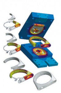
Sigmasoft simulates the following processes: filling, packing, cooling, venting, shrinkage, warpage, stress, ejection, post molding, hot runners, multi-cycle, multi-component, and insert over-molding.

Sigmasoft filling and packing simulation predicts temperatures, pressures, velocities, crystallization, and shearing at any location at any time to determine manufacturability and ensure a balanced mold design. Weld lines, sink marks, voids, and air traps are also valuable outputs to eliminate the potential for part defects.

The thermal distribution inside an injection mold depends on many factors. In the same way as the polymer flows three dimensionally into the cavity, the heat also flows three dimensionally between inserts, part, mold, and thermal control. A multi-cycle analysis enables you to simulate the quasi-stationary state of a m old including all local temperature differences and consequently to perform a much more precise filling simulation based on the steady state temperature distribution. Sigmasoft accurately calculates the complex thermal distribution in the mold coupled with polymer flow.

The software simulates the impact of the ejection system on the part and offers insight into the ejection system design. Ejection forces are predicted to understand their impact on final part quality. The ejection system may also be evaluated to determine the porper quantity of ejector pins.

Proper venting is critical to the injection molding process. Without proper venting, quality and flow imbalances are common issues. Sigmasoft lets you model vents into the simulation to optimize location and size, and view the impact of trapped air on the flow front. View trapped air pockets, air pressure, and air temperature in the cavity.

The software predicts post-ejection stress relaxation and crystallization of the part which often provides a more accurate warpage prediction. A second heat cycle may also be simulated, taking into account the entire process history.

3D CAD models of the part geometry and the entire mold if needed can be imported directly into Sigmasoft in multiple formats including STEP, STL, SAT, Pro/E, or Catia. The software also includes tracer particles to help visualize what is happening behind the flow front. These tracers are shown during the filling, packing, and cooling processes.

Sigmasoft

www.3dsigma.com

Filed Under: Simulation Software Tagged With: 3D CAD, analysis, Catia, plastic injection molding, Pro/E, Sigmasoft, simulation, warpage

Primary Sidebar

3D CAD NEWSLETTERS

MakePartsFast

Follow us on Twitter

Tweets by 3DCADWorld

Footer

3D CAD World logo

DESIGN WORLD NETWORK

Design World Online
The Robot Report
Coupling Tips
Motion Control Tips
Linear Motion Tips
Bearing Tips

3D CAD WORLD

  • Subscribe to our newsletter
  • Advertise with us
  • Contact us
Follow us on Twitter Add us on Facebook Add us on LinkedIn Add us on Instagram Add us on YouTube

3D CAD World - Copyright © 2021 · WTWH Media LLC and its licensors. All rights reserved.
The material on this site may not be reproduced, distributed, transmitted, cached or otherwise used, except with the prior written permission of WTWH Media.

Privacy Policy