• Skip to primary navigation
  • Skip to main content
  • Skip to primary sidebar
  • Skip to footer

3D CAD World

Over 50,000 3D CAD Tips & Tutorials. 3D CAD News by applications and CAD industry news.

  • 3D CAD Package Tips
    • Alibre
    • Autodesk
    • Catia
    • Creo
    • Inventor
    • Onshape
    • Pro/Engineer
    • Siemens PLM
    • SolidWorks
    • SpaceClaim
  • CAD Hardware
  • CAD Industry News
    • Company News
      • Autodesk News
      • Catia News & Events
      • PTC News
      • Siemens PLM & Events
      • SolidWorks News & Events
      • SpaceClaim News
    • Rapid Prototyping
    • Simulation Software
  • Prototype Parts
  • User Forums
    • MCAD Central
    • 3D CAD Forums
    • Engineering Exchange
  • CAD Resources
    • 3D CAD Models
  • Videos

Rapid Prototyping

3D Printing ( and CAD) Save Lives

August 17, 2021 By Leslie Langnau Leave a Comment

Prosthetic limbs have been printed for years. So when a global crisis hit, additive manufacturing was ready to contribute quickly to life-saving equipment.

Jean Thilmany, Senior Editor

In the early days of the pandemic, engineers quickly designed and printed medical protective gear and respirator valves. The response demonstrated the lifesaving potential the technique could have in the medical realm. But many in the field already knew the potential 3D printing has to enhance patients’ quality of life. For years, the method of creating a 3D object by depositing a material in layers has been used for customized prosthetic limbs.

While many printed medical devices are still under investigation, patients who wore early 3D-printed limbs—only about 20 years ago—recognize how far additive manufacturing has come in healthcare in that short time. Scientists have even established a new field—3D bio-printing—that explores everything from the prosthetic iris to an artificial heart to the printing of customized pharmaceuticals.

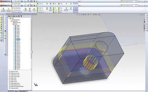
But bio-printing couldn’t exist without computer-aided design. A medical device CAD model—whether a prosthetic leg or a respiratory mask—exists before the physical prototype does, the same as in other manufacturing processes. Across all types of manufacturing, the engineer redesigns and analyzes a model many times before creating a physical prototype.
Rather than feeding out instructions to, say, a CNC machine, the CAD files used for additive manufacturing instruct the printers on how much material to deposit at particular locations.
That precision along with the range of materials 3D printers can use, even living tissue, drives medical research across all categories.

For instance, doctors at Northwestern University announced in June that they’d used images of volunteers’ irises, Photoshop, and AutoCAD software to create a prosthetic iris. It’s intended for people with aniridia, a rare condition in which a person is born without an iris. The iris controls pupil size in response to light, so a prosthetic iris could help its wearers see better in all types of light conditions.

Meanwhile, researchers at the Yonsei University reported their work on a 3D-printed cosmetic, prosthetic eye through use of mapping, design, and printing technology. The paper appeared in the February 2021 journal Korean Ophthalmology.

Studies like these are an extension of one of 3D printing’s first medical uses, the creation of customized, artificial limbs. When the technique was still new, doctors discovered additive manufacturing created better-fitting, lighter, stronger and more flexible prosthetics than traditional methods; and in much less time.

Printed limbs can be closely customized to the wearer through the use of imaging systems like computer-aided tomography, which exactly maps the patient’s body, often the remaining stump of a leg, where the artificial limb will attach. The CAT scans are sent to a CAD system where they’re converted into digital model of the body. Then, engineers can create a prosthetic model that exactly fits the shape of the body.

When the CAD model is complete, the software sends instructions to the 3D printer, which prints the customized prosthetic by building it up, layer upon layer of a material such as plastic or metal.

The result is a much better fit for patients, a lighter prosthetic, and—in many cases—a more affordable device, say researchers like Hugh Herr, the director of the Biomechatronics Group at the Massachusetts Institute of Technology.

An artificial leg printed leg a decade ago—even some printed now—looks more like a traditionally created prosthetic limb, which is die-cast of aluminum or titanium. Patients who wear these standard limbs may move awkwardly due to the device’s limited range of motion. The people who wear them may have difficulty with walking, running, and picking up objects, Herr says.

After the Civil War, prosthetic legs became more common within the United States, especially jointed legs such as this one. The design hadn’t changed much through the years; until additive manufacturing. Hugh Herr, the director of the Biomechatronics Group at the Massachusetts Institute of Technology is helping create “biohybrid” prosthetics, partly using 3D printing, that work in harmony with the humans who wear them, including himself.

Today’s myoelectric prosthetics are fitted with robotics and sensor technologies so their movements closely mimic that of a human hand or foot. Through more natural movement, wearers will have an easier time walking, running or picking up and carrying objects, movements that today can be somewhat awkward due to the limited motion of the prosthetic, Herr says.

In today’s parlance these are “bionic limbs,” so-called because their capabilities are so much greater than the early 3D-printed limbs.

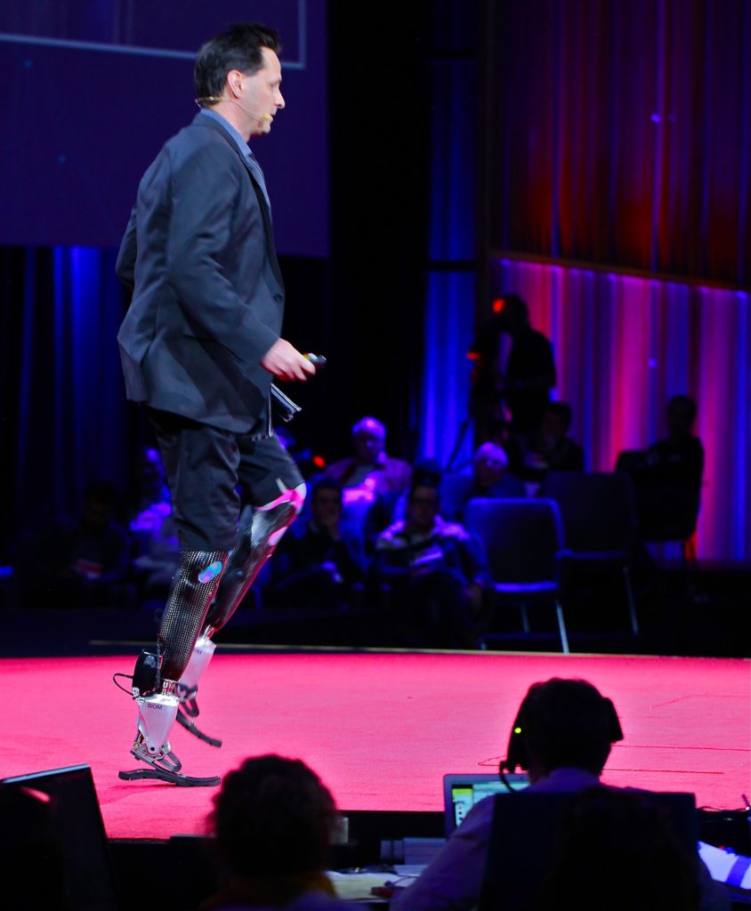
Herr’s work has been instrumental to bionic limbs. But he wants to extend the field even further. He’s helping create “biohybrid” prosthetics that work in harmony with the humans who wear them.

His mission is personal as well. Herr lost both legs to frostbite while rock climbing in New Hampshire’s White Mountains in 1982. He still climbs. In fact, Herr says he climbs better with the legs he’s recently developed than he did before the accident. He expects future advances in prosthetics to help him climb with even more speed and agility.

Also in the near future, wearers may well control the prosthetic limbs the way most everyone controls their natural arms and legs; without a thought. Or rather, with a subconscious thought. Researchers at Johns Hopkins University, for example, are studying brain-machine interfaces to control movement of prosthetic limbs and include touch perception.
Additive manufacturing will keep up with these advancements, Herr says.

Medical printing in a pandemic
Printed prosthetic limbs showed the medical community that 3D printing had a place in healthcare. And thankfully so; as the year 2020 proved that additive manufacturing could save lives.

When the COVID-19 pandemic froze traditional supply chains, open-source CAD systems and 3D printers were able to get devices into the hands of healthcare providers who faced shortages in medical and testing equipment and in protective gear, says Aamir Nazir, a researcher at the National Taiwan University of Science and Technology’s High-Speed 3D Printing Research Center. He and fellow researchers studied the rise of the rise of 3D printing and smart CAD during the shutdown, publishing their findings in the October 2021 Journal of Manufacturing Systems.

Researchers at Duke University and the Pratt School of Engineering modified a surgical helmet to incorporate a 3D-prinited filter to create a a protective device to safeguard surgeons during the COVID-19 pandemic.

When the lockdown began in earnest, “it became obvious very fast that traditional manufacturing and supply techniques weren’t going to work,” Nazir says.

“This created the need for geo scattered, small, and rapid manufacturing units along with a smart computer aided design facility,” he says.

The medical devices printed during this time helped saved lives. The devices could be designed and printed much cheaper, and in much less time than with traditional manufacturing methods. Not to mention, the devices could be made right on the spot, or nearby and available immediately, no shipping required, Nazir says.

This image shows how a retrofit surgical hood from Duke University and Pratt School Engineering is worn to shield surgeons’ faces while still allowing them to wear headlights and loupes directly on their heads.

Medical manufacturers helped the cause by providing 3D printable models on the cloud, rapidly scaling the movement toward 3D cloud manufacturing, he adds.

In those early days of the pandemic, a team of Italian engineers stepped up to make a 3D printed version of a vital respirator valve, a Reuters news report stated.

A hospital in Chiari, an area in northern Italy hit hard by the pandemic, urgently needed valves for the respirators that kept many patients breathing. When the valves’ manufacturer couldn’t get them out in time, Christian Fracassi volunteered his engineers at Isinnova, a 3D printing company he founded.

His staff of 14 engineers immediately began tinkering with the design of the Venturi valve, a small but important valve that kept respirators functioning.

Fracassi took the resulting CAD file and a 3D printer directly to the hospital, discovered it worked, and quickly printed 100 valves. That evening, at least 10 patients were using respirators fitted with the printed valve, Reuters reported.

The Italian hospital wasn’t alone.

The need for the Venturi valves was great. By March 18, more than 100 medical facilities and engineers had asked Percassi to share his CAD file. He couldn’t share the file, he told them, the correct course of action would be to contact the manufacturer first.

In Italy, 3D-printed parts have to be certified. But emergency rules in that country waived the requirement, according to 3D Printing Media Network, which started an Emergency AM Forum to help share designs and ideas during the crisis. Other countries may not have similar waivers, Percassi reasoned.

The next day engineer Filib Kober posted a free model of the Venturi valve he’d made with the GrabCAD open-source system.

Within a week, the model had been downloaded many times and was already being updated. The Kober model couldn’t be printed on the smaller, desktop printers. But individual “makers” only had access to desktop printers, says engineer Useriu Daniel. By the end of March, he’d released his valve-design iteration, created with Catia V5 software. Daniel is an engineer at Romanian researcher organization INCDT-COMOTI.

His updated design can be made with through fused deposition, the method used by desktop printers, he says. The model also had a new feature and the inner surfaces were optimized for fluid flow.

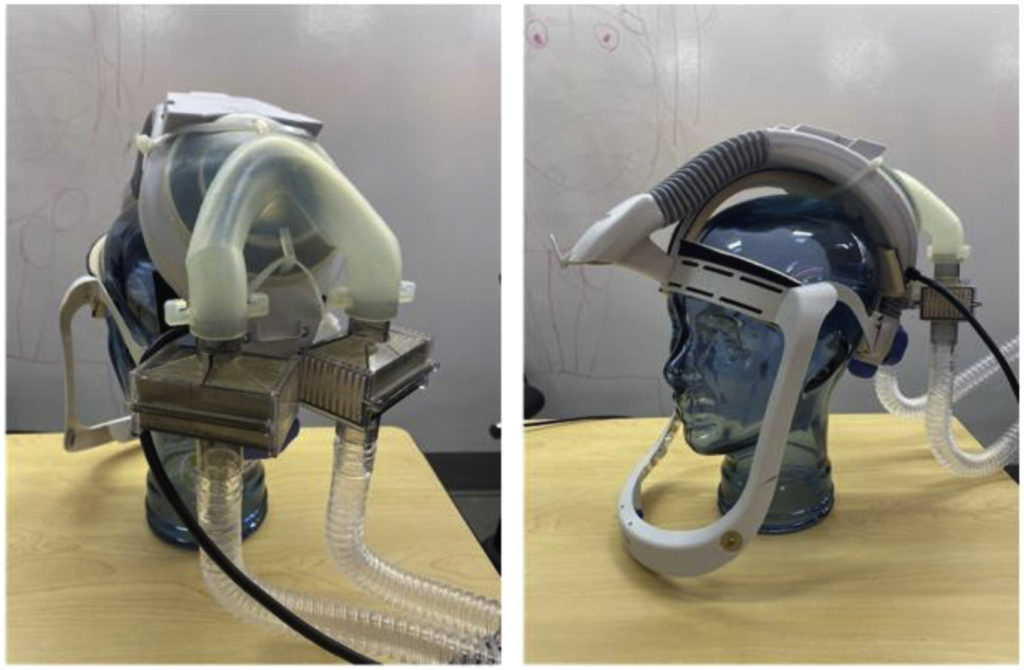
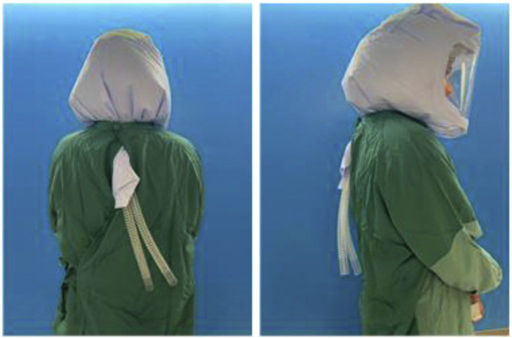
Other engineers quickly designed parts that could be printed or could be integrated with existing designs; and even with existing devices. Engineers at Duke University collaborated with students and researchers at the Pratt School of Engineering to retrofit arthroplasty helmets—a surgical hood. The updated hoods safely shielded surgeons’ faces while still allowing them to wear headlights and loupes directly on their heads.

The engineering team created a manifold that could be 3D printed and incorporated onto existing helmets. CAD allowed for the quick testing and redesign needed for the project, says Melissa Erickson, a spine surgeon at Duke University who helped spearhead the project.
“The engineering team designed and created the final adapter just in 12 days. They were able to come up with different design alterations while testing to make the final manifold, which is only possible because of 3D printing,” Erickson says.

It’s hard to believe, with these quick-thinking creations at a time of crisis, that additive manufacturing is still in its early days in the medical field. Watching a video of Herr scale a mountain on his “bionic legs” does nothing to dispel that.

Though the future of the field is almost unimaginable, Herr thinks he’s got a pretty good handle on the cutting edge of the present. By giving wearers access to these new prosthetics, he’s giving them access to the part of themselves that moves naturally through the world.
By opening up lives like this, by helping to save lives, 3D printing and CAD is on its way to becoming a big part of healthcare.

Filed Under: CAD modeling, Make Parts Fast, Rapid Prototyping

Latest release of Parasolid offers functions for blending, tapering, offsetting, and hollowing

July 13, 2021 By Leslie Langnau Leave a Comment

Siemens Digital Industries Software released the latest version of Parasolid software, its open geometric modeling technology employed by over 4 million users across the world. The scope of Parasolid Convergent Modeling technology continues to expand with new functions for blending, tapering, offsetting, hollowing and thickening mixed models. Designers can benefit from these new model editing capabilities when they need to integrate their precisely engineered (B-rep) designs with organic (facet-based) shapes. Such organic shapes are proliferating in design workflows through the application of topology optimization and 3D scanning.

To meet a variety of diverse customer needs, the latest release delivers new functions across several different application areas and adds support for emerging hardware platforms. For applications in additive manufacturing, new lattice modeling functions help users to create structures that benefit from a high strength-to-mass ratio. In addition, slicing operations have been improved to aid 3D print preparation.

Istvan Csanady, CEO at Shapr3D spoke of the breadth of functionality that Parasolid is now offering and the ease with which the latest Parasolid release could be deployed in applications for Apple’s new M1 chip (Apple Silicon). According to Csanady, “Parasolid is so feature-rich, I don’t think there is an application in the world that exposes 90% of the functionality and porting our software to Apple Silicon was super-straightforward – we just took the Parasolid binaries and integrated them immediately.”

Recognizing the needs across the diverse ecosystem of Parasolid users on mobile, desktop and the cloud, Parasolid now supports deployment across an expanded range of hardware platforms including Windows 10 and macOS 11 on ARM-based devices.

The Parasolid geometric modeling kernel is used in Siemens’ own Solid Edge software and NX software, and is at the core of the Xcelerator portfolio’s open and flexible ecosystem. Parasolid is also used in over 350 other applications from industry-leading CAD/CAM/CAE/AEC software vendors.

Siemens Digital Industries Software
www.sw.siemens.com

Filed Under: Rapid Prototyping, Siemens Digital Industries Software Tagged With: Siemensdigitalindustriessoftware

2020 & beyond: 6 more megatrends to watch in engineering modeling & simulation

June 8, 2020 By Leslie Langnau Leave a Comment

Bruce Jenkins | Ora Research

Early last year we reviewed in this blog post eight megatrends in engineering modeling and simulation that dominate the thinking and decision-making of engineering organizations and their technology providers today, and that we believe will continue to do so well into the years ahead. We wrote then:

This second decade of the twenty-first century is witnessing an explosion of invention and innovation in digital engineering technologies unrivaled since the 1980s, when so many foundational tools and methods were either created or brought to practical fruition. Here are eight megatrends that we believe will drive generational leaps forward in engineering modeling and simulation technologies, methods and work processes through 2020 and well beyond:

  • Simulation-led, systems-driven product development.
  • Democratization of engineering modeling and simulation.
  • Simulation app revolution.
  • Design space exploration.
  • Topology, materials and process optimization for additive manufacturing.
  • Simulation for the Industrial IoT and Industry 4.0.
  • Big-data analytics in simulation.
  • Cloud HPC for simulation.

Now, here are six more large-scale trends that we think are already beginning to drive major technology developments and end-user investments aimed at fostering cost, schedule, quality, performance and innovation improvements in the engineering and production of discretely manufactured products (many will benefit process manufacturers and other AEC industry participants as well):

  • 21st– century data management: Separate the data from the data model (Aras, Onshape, Frustum…).
  • From PIDO to fully automated design space exploration: 20+ years of evolution—then a revolution.
  • New requirements-management technologies that automatically link—via new systems-level engineering technologies—requirements fulfillment during the course of system-level product design (MapleSIM, Simulink…) back to digitally captured system requirements definitions (SysML, Rational Rhapsody…), and automatically track and report divergences and convergences between the two as the design evolves.
  • Generative design design space exploration: What’s alike? What’s different? When is each appropriate?
  • AI and ML (machine learning) in engineering modeling and simulation—the next steps beyond big-data analytics for simulation.
  • Further breakthroughs in co-simulation: Simultaneous instead of step-wise simulation of multiple physical domains, and at multiple (mixed) fidelities—0D, 1D, 2D, 3D; also 4D and 5D in AEC.

Previews

21st– century data management

Aras’s insight to separate the data from the data model makes them, a bit ironically, the technology vendor that will relieve legacy PLM vendors of the prohibitive burden of somehow hoisting their SQL-based PDM offerings into the cloud, yet still link them into today’s truly “open” world. Because Aras’s technology architecture has already done it for them, before them.

And without charging a penny for the technology. Aras makes its software available as freeware. Users can download, evaluate, and implement it in production usage—all for zero dollars. If users then need customization and integration to link into their unique multi-application environments, Aras is available to do this, for fair and reasonable service fees. An extraordinarily apt 21st-century business model, we think.

From PIDO to fully automated design space exploration: 20+ years of evolution—then a revolution

This breakthrough was sparked by HEEDS from Red Cedar Technology, a paradigm-disrupting startup that commercialized university-developed technology under the leadership of Bob Ryan, and was subsequently acquired by Siemens PLM. HEEDS has set a new direction now being pursued by almost every major DSE technology provider.

Generative design vs. contemporary design space exploration

When early adopters of generative design technology discover what fully automated design space exploration technology can do, will they feel underserved by their generative-design technology providers putting forth tools that still require, today, an arguably unnecessary exertion of effort by engineers and designers in making decisions that the software should be making for them?

Or, instead, is generative design an entirely appropriate technology for disciplines and end-user markets where not all problems and sought-for outcomes can be expressed in an entirely determinative manner? The jury is still out on this one, we believe. After users gain more experience with both approaches—and with continuing maturation of both technology classes—time will tell.

Looking forward

Watching the answers to all these questions take shape is going to be fascinating. We greatly look forward to following and reporting here on these and many more game-changing technologies and trends as they unfold in the quarters and years to come. Stay tuned!

Selected background reading

Aras acquires Comet Solutions

HEEDS MDO

MapleMBSE from Maplesoft radically expands accessibility of model-based systems engineering

CosiMate from Chiastek: Co-simulation conduit for multifidelity systems modeling

Cloud-native CAD will disrupt the PLM platform paradigm

Filed Under: CAD modeling, News, Rapid Prototyping, Simulation Software Tagged With: brucejenkins

Additive manufacturing used for local PPE solution in Belgium

May 14, 2020 By Leslie Langnau Leave a Comment

Bruce Jenkins | Ora Research

“Over the last month or so, the Coronavirus or COVID-19 pandemic has captured our collective consciousness across the globe and forced us to rethink every aspect of our professional and personal lives,” says Kaustubh Nande, Global Marketing Director at Hexagon’s| MSC Software. “Hexagon too has taken some concrete steps to protect our workforce and to minimize risk to the supply of our products and our services to our customers. For instance, we put in place a work from home program to use our smart manufacturing software packages and put together additional online learning options for manufacturing professionals.

“One interesting project undertaken by our team in Belgium was about using in-house knowledge and available material and tools to solve a specific issue posed by the COVID-19 outbreak. Across the globe, there have been several reports of hospital workers suffering from shortages in Personal Protective Equipment (PPE), due to the unprecedented demand across the world.”

The Hexagon | e-Xstream team at Belgium “heard about a requirement for PPE, specifically face shield holders, in a nearby hospital. The team decided to chip in and do its bit by conceptualizing an additive manufacturing solution to the problem. The team had access to a 3D printer and suitable material within the office. The team first found an open CAD model that was available online and plugged it into the 3D printer and used the design to 3D print some face shield holders right at the Hexagon office.”

The company says that, “backed by a thorough understanding of additive manufacturing techniques and knowledge about the use of Digimat and e-Xstream in plastic printing, the team was able to think smart and deliver on what the doctors required. In the coming weeks we will also be increasing the production count. The finished product met the need for equipment that could protect hospital staff. The key thing is these plastic PPE liners can be disinfected easily and reused by the hospital. Depending on material available you can print in various colors for easy identification.”

MSC concludes, “This gesture by our Belgium team stands out as a great example of how the right hardware and software tools combined with the proper knowledge can bring in quick, practical solutions to solve real-life issues quickly and effectively.”

Work-from-home information

MSC adds: “Our customers, employees, and partners are at the heart of what we do. Our concerns and well wishes go out to all those directly and indirectly affected by the COVID-19 pandemic. We are taking the threat very seriously by protecting our workforce and minimizing the risk to the supply of our products and services to you during this time. Across the globe, the measures being put in place to reduce the spread of COVID-19 means that many companies are asking their employees to work from home.

“Our goal is to offer the level of responsiveness and support that you have come to expect from MSC. If there is anything we can help you with, please do not hesitate to contact us. Please visit mscsoftware.com/work-from-home/assistance-programs for complete details on our current assistance programs, as well as check back for additional announcements in the coming days.”

Kaustubh Nande

Hexagon’s COVID-19 information page

Filed Under: Company News, Hexagon software, Rapid Prototyping, Smart manufacturing software Tagged With: hexagonsoftware

C3D Vision 2019 helps designers visualize geometric data

December 19, 2018 By Leslie Langnau Leave a Comment

C3D Labs, Moscow, Russia, released C3D Vision 2019 visualization module, a part of C3D Toolkit for developers of engineering software. C3D Vision operates with polygonal models and is responsible for drawing visual scenes in 3D applications.

The 2019 release is integrated more closely with the C3D Modeler geometric kernel. To automatically generate scene graphs based on mathematical models, developers call just one function.

The multi-threading support found in C3D Toolkit is also implemented in C3D Vision 2019. There is an option to calculate polygonal models for visualization objects (based on mathematical representations of the geometry) in synchronous or multithreading mode. Searching objects and drawing is also performed in either of these two modes.

The new version of the 3D engine quickly and easily creates modern 3D design projects. Together with the C3D Toolkit’s other software development modules – the geometric kernel, a parametric solver, and file converters – C3D Vision provides CAD developers with a solution for constructing, editing, displaying, and converting geometry.

C3D Vision 2019 new functions include:

• PMI. The module implements three aspects of product and manufacturing information (PMI): linear, diametrical, and angular dimensions. In turn, dimensions may be applied with measurement tools.

• Slots and signals are now the primary form of communication between C3D Vision objects. The enhancement reduces the amount of source code needed to interact with geometric objects and their corresponding representations, as well as to interact with camera control processes and to update rendering frames.

• Metadata provides additional information about C3D Vision objects. It helps to find the name of an object and its properties, and to check whether objects inherit certain classes.

• Native events is the new and simplified event model in C3D Vision. It handles events from input devices, such as the mouse and keyboard, and can be used to override other devices.

• Object detection now generates signals as the mouse moves, and identifies the object pointed to by the cursor. A structure that lists the identities of objects found by the cursor is transferred to the slot. Using the identifiers, developers can search for objects or their primitives as mathematical representations.

• Cutting Plane tool now performs cross sections using OpenGL, which gives quicker results. (This replaces the older method of modifying the topology of solid sections.) The tool can make sections with several planes and closes the cutting point. A material can be specified for each section plane separately.

With the 2019 release, the architecture of the Vision engine has undergone changes, giving customers the opportunity to create objects, as well as write processes for creating and editing objects.

One such customer is the Russian Federal Nuclear Center VNIITF of ROSATOM, which uses C3D Vision together with the C3D Modeler’s geometric kernel and C3D Converter to develop products for computer-aided engineering and calculations.

The RFNC Zababakhin All-Russia Research Institute of Technical Physics (Snezhinsk) licensed C3D Toolkit in 2016. That was the year that they initiated in-house software development using C3D Toolkit for geometric modeling and import/export of finished geometry through exchange formats.

C3D Vision 2019 is available for free testing as part of the C3D Toolkit, or as a separate module.

C3D Labs

Filed Under: News, Rapid Prototyping Tagged With: c3dlabs

GENERATE for Windows OS is an interactive Generative Design software

October 2, 2018 By Leslie Langnau Leave a Comment

Frustum Inc., innovator of interactive generative design solutions, announced a new release of its GENERATE software. GENERATE represents a new paradigm for design, interactive generative design, which fundamentally alters how products are modeled for manufacture by allowing engineers to interact and iterate in real time with generative design models. As a result, engineers can develop multiple perfectly designed and optimized models to identify the best solution in a matter of minutes versus hours or days previously.

Designed to meet the complex needs of design for manufacturing, GENERATE is a 3D design software to offer interactivity with generative design models. It combines the creativity of the engineer with artificial intelligence to significantly shorten the time of designing high performing products – effectively delivering a near real-time interaction with a generative design model, generating designs by functional requirements and producing a result that is ready for manufacture. Parts and products designed through this process are lighter, stronger and use far less materials than those designed using traditional CAD software.

“With GENERATE, designers and engineers can interactively specify the functional requirements of their design and the design will automatically be modeled to meet those requirements. The design output is functional and does not have to be remodeled in CAD,” said Jesse Coors-Blankenship, CEO, Frustum Inc. “We developed GENERATE on a multi-threaded architecture that was built from the ground-up to deliver faster design output by leveraging both CPU and GPU computing optionally. GENERATE will redefine how manufacturers get products to market, reduce materials costs and improve the overall performance of products.”

Built on its patented generative engine, TrueSOLID, GENERATE couples advanced topology optimization and simulation algorithms with real-time interaction to quickly produce high-performing, ready to manufacture mechanical designs. It is functionally parametric and facilitates perfect blending of generative geometry to traditional surface-based CAD with engineering precision. The technology is currently being commercially licensed to Siemens PLM software and integrated into Siemens NX and Siemens SolidEdge.

The new Windows-based GENERATE design software includes the following features:

  • Native CAD file import
  • Single and multi-body optimizations
  • Multiple loads and constraints
  • Realtime FEA
  • Standard and user-defined material library
  • Interactive design changes
  • Windows 64-bit multi-threaded architecture
  • STL export with user-defined resolution
  • Optionally GPU-enabled with NVIDIA

The GENERATE design software is now available.

Frustum Inc.
www.frustum.com

Filed Under: Company News, Rapid Prototyping Tagged With: frustrum

BMF Material Technology teams up with Onshape for high-precision manufacturing

September 17, 2018 By Leslie Langnau Leave a Comment

Onshape, a leading 3D cloud CAD platform, announced a strategic partnership with BMF Material Technology , a world leader in micro/nano-scale 3D printing and  precision manufacturing.

Micro/nano-scale 3D printing is a technology in high demand by manufacturers of extremely small and complex parts such as connectors, endoscopes, cardiac stents and tiny springs.

BMF plans to use Onshape’s real-time data management platform to speed up collaboration and communication with its customers, helping them optimize their CAD models for the most accurate printed parts.

“On a daily basis, there are companies all over the world – throughout Asia, Europe and the United States – contacting us for printing small parts with our nanoArch  printers,” says BMF’s CEO, Dr. Xiaoning He. “Before using Onshape, we had to email CAD files back and forth with our customers. But now we can have our team in China and our customers overseas work together on the same model at the same time. It has really improved our efficiency and speed, and Onshape is the only CAD system that can deliver this capability.”

As BMF customers collaborate with the company’s additive manufacturing experts to refine their CAD models, Onshape records every edit in a comprehensive history log. By clicking on any point in the timeline, Onshape users can instantly go back to any prior state of the design.

“The edit history log is a huge advantage for us,” adds He. “It speeds up the learning curve for our customers. We’re in the 3D printing business, not the design business. Onshape will help us teach our clients how to deliver better designs the next time.”

Onshape is a CAD system that combines advanced 3D modeling tools with design data
management in a secure cloud workspace. Its database architecture eliminates the security risk and version control problems created by uncontrolled file copies because only one master copy of the CAD data is stored in the cloud, accessible only by different levels of permissions (edit, view-only, commenting, etc).

BMF
www.bmftec.com

Onshape
onshape.com

Filed Under: Onshape, Rapid Prototyping Tagged With: OnShape

Frustum Generate topology optimization plus 3D Systems DMP expertise slash weight of GE Aircraft bracket 70%

March 24, 2017 By Leslie Langnau Leave a Comment

Bruce Jenkins, Ora Research

A perennial engineering challenge is designing a part to meet performance requirements while observing design constraints imposed by manufacturing processes. Conventional subtractive machining offers sharply limited ability to cost-effectively produce complex geometries, especially biomorphic shapes and lattice structures. The result of those manufacturing limitations is often components and products with suboptimal functionality and performance.

But today, with advances in 3D printing and especially direct metal printing (DMP) swiftly making these technologies more and more available and effective, many constraints imposed by traditional manufacturing processes are going away. At the same time, software technologies for multidisciplinary design exploration are emerging to help engineering and manufacturing organizations make the most of these new production processes. In particular, rapid advances in topology optimization technology are helping engineers generate the most efficient designs for single-step manufacture by latest-generation DMP systems. With this combination of new technologies, what the engineer designs is essentially what gets manufactured, with very little of the time- and labor-intensive manufacturing engineering that before now was needed to turn engineering intent into machinable reality.

The business value of this confluence of new technologies was dramatically proven in a recent project by software developer Frustum and 3D Systems’ Quickparts on-demand parts service. The project was part of a public challenge to industry by GE Aircraft to reduce the weight of an aircraft bracket while maintaining the strength needed to meet all of its functional requirements, primarily supporting the weight of the cowling while the engine is in service.

Design-critical nature of weight

Since the beginning of motorized travel by land, air and sea, engineers have striven to balance the competing objectives of maximizing strength while minimizing weight. This balancing act has become especially critical in recent years, with swiftly growing and globalizing competition among manufacturers, ever stricter efficiency and emissions mandates, escalating costs and schedule pressures.

Weight is an especially crucial factor in modern aircraft engineering. Although a Boeing 737 weighs some 65 metric tons, shaving just a single pound of weight from the design yields fuel cost savings of hundreds of thousands of dollars per year for each plane. Multiplied by the total number of aircraft currently in operation worldwide, those savings approach $10 million annually, according to a GE Aircraft white paper.

Topology optimization of the design

In the GE Aircraft challenge, Frustum’s Generate topology optimization software provided the first steps in tackling critical weight-versus-strength issues. Topology optimization determines the most efficient material layout to meet the performance requirements of a part design. It takes into consideration the given spatial volume allowed, load conditions on the part, and maximum stresses allowed in the material.

Generate automatically generates optimized geometries from existing CAD files. It models material structure among the design features to generate optimally stiff and lightweight structures. Smooth and blended surfaces reduce weight and minimize stress concentrations.

“Based on an existing conventional part design, our software automatically produces optimized geometry for additive manufacturing, without needing to do any remodeling,” says Frustum CEO Jesse Blankenship.

Unlike parts manufactured by traditional CNC or casting methods, the complexity of the model generated by topology optimization is of no concern, as DMP handles extremely complex models as easily as simplistic ones.

3D printing expertise from 3D Systems On Demand Parts Manufacturing service

Once the initial design was generated, 3D Systems’ expertise came into play. Its On Demand Parts Manufacturing service, available through the company’s Quickparts online portal, is a leading provider of unique, custom-designed parts, offering instant online quoting, expertise in 3D design and printing, and manufacturing services support. The worldwide service is well versed in the most complex aspects of direct metal printing.

“Direct metal printing is much more complex than plastics printing,” says Quickparts business development manager Jonathan Cornelus. “We help our customers to develop parts suitable for DMP, with minimized risks for part distortions or build crashes. We print components using optimized parameters based on our long-term experience in printing parts for customers.”

Manufacturing process

With the GE Aircraft bracket, Frustum’s Generate imported the original CAD file and performed the topology optimization in one step, delivering an STL file for printing. 3D Systems provided manufacturing advice on the process, material specifications, best build orientation to deliver optimal part properties and achievable tolerances, and identified potential risk for deformations.

The part was printed on a 3D Systems ProX DMP 320 system. Preset build parameters, developed by 3D Systems based on the outcome of nearly half a million builds, provide predictable and repeatable print quality for almost any geometry. An entirely new architecture simplifies job setup and offers the versatility to produce all types of part geometries in titanium, stainless steel or nickel super-alloy. Titanium was chosen for the GE Aircraft bracket, based on its superior strength even when material is thinly applied to lower a part’s weight.

Exchangeable manufacturing modules for the ProX DMP 320 system reduce downtime when changing materials. A controlled vacuum build chamber ensures that every part is printed with proven material properties, density and chemical purity. The small portion of non-printed material can be completely recycled, saving money and providing environmental benefits.

Dramatic weight reduction an eye-opener

The completed part met all the load conditions required by the GE challenge and stayed within the specified geometric envelope, while slashing weight a staggering 70 percent. “This is the kind of project that should be a real eye-opener for automotive and aerospace companies,” says Cornelus, “where reducing weight while providing the same or improved functionality is the lifeblood of their design, engineering and manufacturing operations.”

Beyond the design and performance of the part itself, Cornelus points out that topology optimization teamed with DMP can often consolidate multipart assemblies into a stronger single part, eliminating fasteners and connectors that are often the cause of failures, as well as the time and labor of assembly.

Finally, there is the coveted advantage of speed. Production-grade parts in tough materials such as stainless steel, titanium and nickel super-alloy can be turned around by 3D Systems in as little as two weeks to satisfy the ever-shortening schedule demands of myriad industries.

Frustum Inc.
https://www.frustum.com/

3D Systems On Demand Manufacturing
https://www.3dsystems.com/on-demand-manufacturing

Filed Under: Rapid Prototyping Tagged With: Frustrum Inc.

The Evolution of CAD

June 15, 2015 By 3DCAD Editor Leave a Comment

by Darren Chilton, Program Manager, Product Strategy and Development, solidThinking

Designers seeking a solution for creating products for additive manufacturing, look no further than hybrid modelers. Without the constraints of traditional CAD tools, these programs help you explore product designs and create alternatives all in one place.

Computer Aided Design (CAD) software first came onto the scene in the later part of last century to help engineers, designers and other industrial users create accurate, dynamic models quickly. Several programs over the years have done just that: revolutionized the design process, cut turnaround times and enabled more complex product designs. As the industry continues to develop, however, many designers are finding that CAD solutions are too rigid and do not allow enough creative freedom when designing products.

CAD is a great tool for documenting a design after a designer has worked out all the dimensions and details on paper or with physical 3D models. But when it comes to allowing designers the freedom to create new products and experiment with design alternatives, CAD often misses the mark.

A new player is rising in the 3D modeling industry: hybrid modelers. Hybrid modelers pack the power of CAD into a package that is intuitive and includes tools that leave room for greater creativity.

CAD reimagined
CAD programs typically rely on solid modeling, a technique well suited for creating parts to be mass manufactured, but not known for its flexibility. When creating more fluid or organic forms, designers usually prefer polygonal modeling or surface modeling. Each of the three major modeling styles offers advantages and disadvantages. For instance, polygonal modeling makes it easy to quickly flesh out forms, but can be difficult to control the model with exact dimensions. The goal of a hybrid modeler is to blend two or more of the modeling styles into one program that leverages the advantages of each.

The challenge in creating any hybrid modeler is making the different modeling styles play nicely with each other. Most hybrid modelers start as a successful program using one of the modeling styles. When an additional modeling style is packaged with the program, often as a third part plug-in, it may feel disjointed and may not work well with the initial set of tools.

One new program that overcomes this objection is solidThinking’s Evolve. This program was conceptualized as an all-in-one hybrid modeler from the beginning. The program was built to highlight the strengths of each of the three major modeling styles in a cohesive approach. The result is an interface that allows users to seamlessly move between modeling styles.

The core value of a hybrid modeler is the flexibility it gives you. The ability to use multiple modeling styles in one model lets you create the intended forms while still being able to apply precise details with tools like rounds and trims. You also have the flexibility to start a model using one technique then prepare it for manufacture using a different technique.

bicycle-helmet
Clicking the Nurbify button in Evolve 2015 converts the polygonal modeled helmet (left) into a solid NURBS surface (right) with one click.

Above is an example of a bicycle helmet that was designed using polygonal modeling. The designer was able to quickly create the form and design of the helmet, but was left with a model that wasn’t usable for manufacturing. Using Evolve’s Nurbify option, the designer was able to convert the model into a smooth NURBS surface with a single click. The geometry can either be further refined, or sent directly to manufacturing.

Technologies like Nurbify can change the way you approach product design. Instead of creating a mountain of sketches to work out every aspect of a design, you can move into 3D earlier. You can make more accurate decisions earlier in the design process, as well as explore multiple design iterations. Some of the best designs end up being happy accidents that are developed while you experiment with different forms and ideas.

bikeframe
solidThinking’s Evolve was conceived as an all-in-one hybrid modeler. The program was built to highlight the strengths of each of the three major modeling styles in a cohesive approach. The result is an interface that allows users to seamlessly move between modeling styles.

One example is a design for a pen. The designer in this instance fleshed out some basic forms of the pen, then worked through various iterations until a final design was achieved. With Evolve’s flexible set of tools specifically developed for this type of workflow, the designer created these designs in minutes compared to the hours it may have taken in a traditional CAD program.

pen-designs-created-with-solidThinking-Evolve
Using the Construction History feature in Evolve, the designer was able to efficiently create multiple iterations of a pen design.

Creating a one stop shop
In the 3D modeling industry there are several programs that specialize in various parts of the concept creation, modeling, visualization, or manufacturing process. The wide set of options gives you plenty of choices, but often means the model has to be moved between several costly programs along the way.

In addition to creating ease of use between the major 3D modeling styles, hybrid modelers include more complete toolsets to ensure designers work as efficiently as possible. Evolve 2015 includes a completely updated rendering engine that emphasizes ease of use and creates visually stunning renderings.

In this instance, the designer created a design using Evolve, then rendered it using native tools. Thus, Evolve, enables you to keep most — if not all — of your project in one program throughout the process. By packaging multiple functions into one software solution, hybrid modelers are more attractive to emerging manufacturing technologies.

Disrupting traditional manufacturing
One of the most notable emerging technologies today is additive manufacturing. Though the technology has been around for decades, new technologies and tools are making it more accessible than ever. With these manufacturing options, the industry is seeing products with more complex and sophisticated geometry.

Additive manufacturing enables a complete shift in how you are able to design products. 3D printers can make forms that are not possible using traditional methods. Beyond being able to make low volume parts faster, you are able to make parts lighter without sacrificing structural integrity.

bicycle-part
The original part (left) was optimized to remove unnecessary material and resulted in an organic, efficient form (right) ready for 3D printing.

Take the part above, the image on the left is the original part prepared for traditional manufacturing. At 6.2 lb, there is room for weight reduction, but traditional manufacturing methods are not able to handle the complexity of the more efficient structures. In this case, the designer optimized the part in solidThinking Inspire by applying the required loads and constraints, which then removed all the non-essential material. The optimized part was then prepared for manufacturing using Evolve. The result, shown on the right, is an organic structure that reduced the part mass by 35% and brought the final weight below 4 lb. The complex structure is not suited for traditional manufacturing, but is easily handled by a 3D printer.

Similar to traditional manufacturing methods, traditional CAD programs have difficulty handling complex organic structures. To create these structures, designers rely on hybrid modelers and their ability to create organic geometry.

Hybrid modelers and additive manufacturing
Additive manufacturing is making it easier than ever to create new products and prototypes. Similarly, hybrid modelers make it easier to conceptualize the products and prepare them for manufacturing. For this reason, many designers consider hybrid modelers a great solution for additive manufacturing.

coffee-cup-stack
Creating quick iterations of an initial concept is ideal for users preparing products for additive manufacturing.

With Evolve software, the designer can quickly and easily create variations of a design, as shown here with unique mugs. In the world of additive manufacturing, the designer isn’t locked into manufacturing a certain number of products to save costs. This allows greater design flexibility and the opportunity to make changes even after manufacturing has begun.

Using a traditional CAD program, a designer would have to create each one of these iterations separately; this is where hybrid modelers provide a significant advantage. Once the base mug is designed, the designer can create and experiment with several designs in just minutes. The iterations of these designs were powered by a unique construction history feature. While working in the hybrid environment, a designer can make changes to the original design and the entire model updates responsively.

“Evolve’s Construction Tree history lets you seamlessly go back and edit your models without having to start the process over; this is key to help expedite the timeline,” said Jared Boyd, product design manager at Dimensions Furniture.

In addition to making it easier to iterate and create designs, hybrid modelers make it easier to communicate with various members of the manufacturing process with options to export the model in most major 3D formats or create photorealistic images and animations.

CAD, evolved
CAD programs can be beneficial in certain areas of product development, but with the introduction of hybrid modelers, designers are free from the constraints of traditional CAD programs and can create innovative products faster and easier. Not only do these programs lead to greater efficiency, they also ease communications between designers and vendors while leaving plenty of room for creativity.

The future relationship between additive manufacturing and hybrid modelers is exciting. Huge advances are already being made in industries with high cost, low volume products like aerospace, defense and medicine.

Reprint info >>

solidThinking
www.solidthinking.com

Filed Under: CAD Blogs, CAD Industry News, General Blogs, Rapid Prototyping Tagged With: solidthinking

Inverse-kinematics software helps design modular robots for 3D printing

March 1, 2015 By 3DCAD Editor Leave a Comment

by Vojislav D. Kalanovic, President of Flexible Robotic Environment, Div. of Biocommerce

Robotic systems being used today, for the most part, lack modular flexibility and other elements that allow easy integration, which often prevent an integrator from bringing them to market quickly. These deficiencies also prevent them from being able to tackle non-serial jobs in a timely and cost-effective manner.

In order to improve robotic system development efficiencies, Bicommerce has created a modular software solution that deploys a user-friendly set of tools that open robotic integration to a broader spectrum of users and markets—from a “bread maker” up to the level of a professional system integrator.

VDK-6000-robotic-metal-3D-printing-machine
The FRE solution was used to create the VDK 6000 robotic metal 3D printing and repair work cell that automates refurbishing, rebuilding, and/or creation of metal components using subtractive and additive technology.

The Flexible Robotic Environment (FRE) is a new, patented technology used in robotics that builds a robot around an application instead of trying to “squeeze” an application within the working volumes that are defined by the physical constraints of a spatial kinematic chain.

In this article, we’re going to look at the FRE application being used with Aerotech’s motion components to form a unique, six degree-of-freedom (6DOF) VDK 6000 Robotic Cell for metal 3D printing and metal part refurbishing. The VDK 6000’s advanced metal printing and metal removal capabilities reparation processes are widely used in industry today.

The Flexible Robotic Environment (FRE)
FRE is robotic software that combines mechanical and motor/drive components with proprietary inverse kinematics software and controls. This configurable and interchangeable, multi-degree-of-freedom robotic package allows the user to “shape” the workspace using standard motion elements. Users can also create a distributed 3D mechanism according to a specific need. Such a mechanism then employs all of its DOF simultaneously in order to provide a desired spatial relationship between a tool and a part at any given instant in time.

The flexibility of the FRE solution permits various systems to be built with virtually the same parts. Examples of this are Bicommerce products, such as the VDK 1000 6DOF material removal system, the VDK 3000 6DOF laser deposition system, the VDK 4000 6DOF direct-write system, the VDK 5000 4DOF ultrasound inspection system, and the VDK 6000 6DOF cold spray system. FRE systems can be expanded at any time and individual components can be replaced and/or exchanged with ease.

The FRE software was used to create the VDK 6000 robotic metal 3D printing and repair work cell that automates refurbishing, rebuilding, and/or creation of metal components using subtractive and additive technology. The VDK 6000 provides a unique, modular motion solution and is designed to execute multiple operations on a single station, enabling production of “first time right” parts—as well as their repair. The VDK 6000 helps deploy the most advanced metal printing and metal removal capabilities for well-established reparation processes widely used in industry today, bringing about faster re-deployment at a lower overall cost.

VDK 6000 offers an auto-connect robotic tool-changer for integration with a variety of conventional and non-conventional processes, such as cold spray, milling, laser scanning, ultrasonic inspection, thermal spray, polishing, laser deposition/drilling and plasma-welding. This flexibility allows various combinations of subtractive and additive manufacturing for 3D printing and repair with a single-system solution.

FRE inverse kinematics capabilities mean that axes are broken into a spatial placement having the best error minimization configuration for a given application. With the FRE approach, VDK 6000 can be scaled up or down depending on customer needs.

The VDK 6000 was built using Aerotech motion components for all six axes. Aerotech components include direct-drive linear motor and ball-screw-driven linear stages, worm-gear-driven rotary stages, drives, and Aerotech’s A3200 machine controller. The accuracy and durability of Aerotech motion components are essential to the precision performance of the VDK 6000 system.

Plotting a path via the SolidWorks API
One of the main features of the VDK 6000 is the path-planning program based on an Application Programming Interface (API) developed for SOLIDWORKS. This capability allows the user to path plan in a user-friendly setting, while exporting motion files that are specific to the hardware configuration, composed in a variety of ways in space and where path-planning is not always intuitive.

The SOLIDWORKS-based API allows the user to:
• create a simple path on a given solid
• create multiple paths that are necessary to perform cladding on a given solid/part
• create slicing models and subsequent paths necessary to create a part provided as a solid model

Creating 3D paths
Users can create a 3D direct-write deposition path on a specific part by using the API that is appended to a CAD package.

3d-direct-write-deposition-path
To create a 3D direct-write deposition path on a specific part, use the API that is appended to a CAD package and executed as shown here. This screenshot shows a 3D path (left) and 3D path formed on an existing 3D surface (right).

Sometimes an application requires a cladding operation, which is the bonding together of two dissimilar metals. When this is required, the user selects surfaces on a given part that are intended for cladding using a mouse selection.

Once the surfaces are selected and cladding parameters are assigned within the API environment, a cladding path is created with only a “click.”

Users can also use the API to select and assign specific tool orientations that are to be used during the cladding process, as well as process parameters including peripheral power, I/O control, speed assignment, cladding direction and tool orientation.

part-ready-for-cladding

user-selected-part-ready-for-cladding
The top screenshot shows an existing part ready for cladding. The bottom screenshot shows the user-selected surfaces of the part for cladding.
cladding-path
Once users select the surfaces that require cladding and the parameters are assigned within in the API, a cladding path is created as shown here.

Creating 3D slicing paths
The API also allows the user to build a part using a slicing application. Once the part is selected within the API environment and the parameters are assigned, a click of a mouse produces a slicing diagram.

sliced-solid-transparent-view
This screenshot shows a sliced solid with a transparent view depicting tool orientations and active paths.

Once the fast and user-friendly path-planning process is complete, you can export the motion path directly into the operating environment of the VDK 6000 for immediate execution. Every FRE system comes with a custom MMI making them even more intuitive for the end-user.

In conclusion…
The robotics industry today lacks the degree of modular flexibility that allows quick and easy integration. The Flexible Robotic Environment (FRE) software solution combines mechanical, motor, and drive components with proprietary inverse kinematics software and controls, resulting in a modular, cost-effective, highly innovative, configurable, and interchangeable multi-degree-of-freedom robotic package that can be applied in many low- to high-level applications.

Reprint info >>

Aerotech
www.aerotech.com

Filed Under: CAD Industry News, News, Rapid Prototyping Tagged With: aerotech

  • Go to page 1
  • Go to page 2
  • Go to page 3
  • Interim pages omitted …
  • Go to page 45
  • Go to Next Page »

Primary Sidebar

3D CAD NEWSLETTERS

MakePartsFast

Follow us on Twitter

Tweets by 3DCADWorld

Footer

3D CAD World logo

DESIGN WORLD NETWORK

Design World Online
The Robot Report
Coupling Tips
Motion Control Tips
Linear Motion Tips
Bearing Tips

3D CAD WORLD

  • Subscribe to our newsletter
  • Advertise with us
  • Contact us
Follow us on Twitter Add us on Facebook Add us on LinkedIn Add us on Instagram Add us on YouTube

3D CAD World - Copyright © 2022 · WTWH Media LLC and its licensors. All rights reserved.
The material on this site may not be reproduced, distributed, transmitted, cached or otherwise used, except with the prior written permission of WTWH Media.

Privacy Policy