• Skip to primary navigation
  • Skip to main content
  • Skip to primary sidebar
  • Skip to footer

3D CAD World

Over 50,000 3D CAD Tips & Tutorials. 3D CAD News by applications and CAD industry news.

  • 3D CAD Package Tips
    • Alibre
    • Autodesk
    • Catia
    • Creo
    • Inventor
    • Onshape
    • Pro/Engineer
    • Siemens PLM
    • SolidWorks
    • SpaceClaim
  • CAD Hardware
  • CAD Industry News
    • Company News
      • Autodesk News
      • Catia News & Events
      • PTC News
      • Siemens PLM & Events
      • SolidWorks News & Events
      • SpaceClaim News
    • Rapid Prototyping
    • Simulation Software
  • Prototype Parts
  • User Forums
    • MCAD Central
    • 3D CAD Forums
    • Engineering Exchange
  • CAD Resources
    • 3D CAD Models
  • Videos

Rapid Prototyping

New Balance Uses 3D Printing to Create Customized Shoes for Runners

December 5, 2014 By Barb Schmitz Leave a Comment

No two runners are the same. This is especially true for athletes competing at the most elite levels. Their foot-strike patterns, degrees of pronation (the amount a runner’s foot rolls inward with each step), and braking and propulsion forces are all unique. However, the extent to which most running shoe models vary is rather limited in comparison.

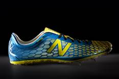
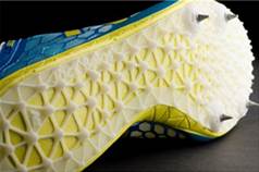
As a result, there are some who believe that personalizing a runner’s shoes, specifically the spike plate that provides traction on the underside of the shoe, can help these athletes become faster on the track.

A proponent of this trend is New Balance Athletic Shoe, Inc., best known simply as New Balance.
The company embraces innovation across all platforms of the business and continuously explore advanced methods for product design and production so it’s no surprise that New Balance has turned to design-driven manufacturing for 3D printing custom spike plates, based on an individual runner’s biomechanics and personal inputs, for their elite athletes.

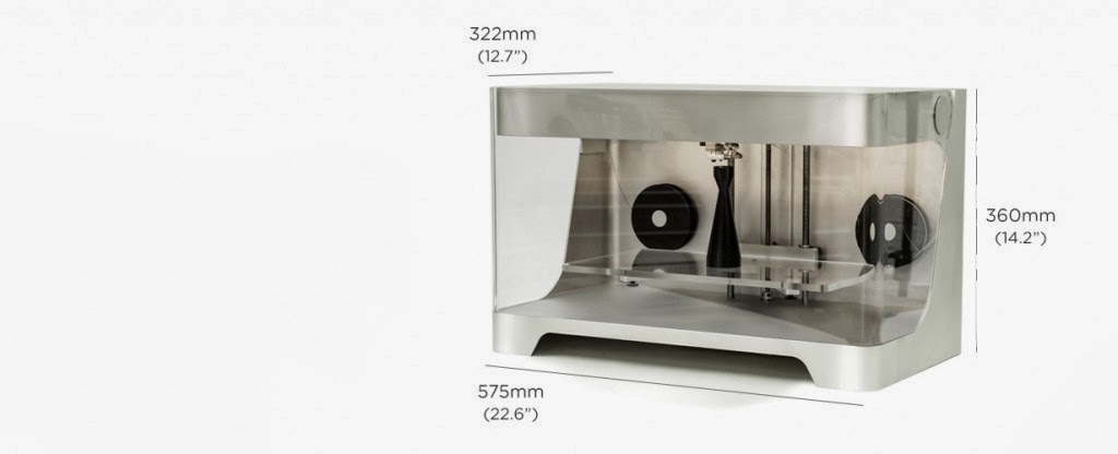
Using a proprietary process to collect race simulation data from Team New Balance runners, the Sports Research Lab then applies advanced algorithms to translate this information into an optimized design that can be additively manufactured on an EOSINT P 395 system—plastic laser-sintering technology from EOS that allows designers to produce, or “grow,” complex geometries that can’t be created using traditional manufacturing techniques.

“There are so many great things that came out of this process, compared to the methods we used in the past to develop and manufacture products,” says Sean Murphy, senior manager of innovation and engineering at New Balance. “This is a totally unique situation where we come away with the runner’s data, generate multiple plates we feel will meet their needs, and actually provide several pairs of track spikes for them to try simultaneously. It’s great to be able to have them identify and respond to each different variation that we produce.”

New Balance Sports Research Lab individually customized spike plates and additively manufactured them using a plastic laser-sintering system from EOS.  Side view of the spike plate attached to the bottom of a track spike.
New Balance Sports Research Lab individually customized spike plates and additively manufactured them using a plastic laser-sintering system from EOS. Side view of the spike plate attached to the bottom of a track spike.

Customized Design with the Runner in Mind

Long before the spike plates are additively manufactured, or even designed, New Balance’s Sports Research Lab collects each runner’s biomechanical data using a force plate, in-shoe sensors, and a motion-capture system worn by the runner. The motion-capture system helps determine the relationship of the foot to the force plate, creating a three-dimensional vector recreation of the foot strike (i.e. the impact of each stride).

The in-shoe sensors show discrete pressure information over the course of the runner’s foot strike and how the runner’s foot interacts with the shoe. When a particular part of the foot exhibits high pressure values, it generally indicates that the associated 3D vector is important to that area of the shoe at that specific moment in time.

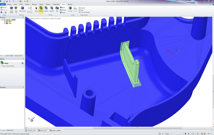
“We establish a relationship between these high pressures and the corresponding forces to help us create a map of forces relevant to each area of the foot,” says Murphy. “A simple example is in the toe area. Generally, when you see high pressure there, it corresponds to a force that is pushing toward the heel to create a propulsive force forward. We use parametric modeling software to process this data and distribute the position of the spike plate traction elements, calculate the orientation and adjust the size of the elements, and incorporate specific runner preferences into the design.”

The designer is then responsible for performing the CAD “cleanup” necessary to create the final product, including touching up model surfaces and making adjustments to accommodate the full-size range of the spike plate. Once the final geometry has been verified, the CAD files are converted to .stl files and uploaded to the EOSINT P 395 system for layer-by-layer manufacturing.

Spike plate customized for New Balance runner Jack Bolas, including his name (seen on the outer edge  of the plate toward the heel).
Spike plate customized for New Balance runner Jack Bolas, including his name (seen on the outer edge
of the plate toward the heel).

Side-lining Traditional Techniques

Track-shoe spike plates have three general characteristics that can vary depending on the length of the race the athlete is competing in and their preferences: The fit, stiffness, and design of the plate all impact the comfort and performance of the runner. Typically, each spike-plate style requires several injection molds for various sizes, all costing thousands of dollars. These molds will run thousands of plates before being retired or replaced, often annually, by a new mold indicating a new model. Currently, the laser-sintered batch sizes produce around four unique plate pairs and take five to six hours to manufacture.

“By laser sintering our customized spike plates we can manufacture on demand, fluidly adjust our process to accommodate different sizes and widths, and update designs without the continuing capital investment required by injection molding,” says Katherine Petrecca, business manager of New Balance Studio Innovation. “The incorporation of the laser-sintered spike plate also allows us to realize a five-percent weight reduction compared to traditionally manufactured versions.” For a competitive runner, the smallest change in weight can make a significant difference.

The development and production of the custom 3D printed spike plates isn’t the only thing that separates these shoes from their off-the-shelf counterparts. While traditional track spikes are commonly made of thermoplastic polyurethane (TPU) and polyether block amide (PEBA), New Balance worked with high-performance materials manufacturer Advanced Laser Materials, part of the EOS family, to develop a proprietary nylon blend.

“We decided to collaborate with ALM on this project because they had experience developing the type of material we were looking for,” says Murphy. “We had worked with them on a previous prototyping project and the variety of materials, as well as knowledge, that they offered made them the perfect partner.”

The spike plates are “grown” in the EOS system from the custom-blend nylon powder, coupled with tailored laser conditions, and yield maximum engineering properties such as tensile and flex moduli, while minimizing build time. Post production includes standard processing techniques such as bead blasting (the process of removing surface deposits by applying fine beads at a high pressure without damaging the surface), after which the plates are processed through a proprietary system for aesthetic finishing and coloration.

The Proof is in the Personal Records: One Runner’s Story

With all the time and energy put into the research and development process, there is still one important question: Does it make a difference in the performance of the runners who wear such customized spike plates? Kim Conley, a member of Team New Balance and U.S. Olympic runner, thinks so.

After initially coming in to the Sports Research Lab at New Balance for the simulation testing in 2012, Conley first wore her customized spike plates for competition in 2013 at the Mt. SAC Relays and has continued to wear them, especially at such important races as the World Championships.

“My shoes are critical to my performance. They’re the most important piece of equipment I have,” says Conley. “As a professional runner, you obviously want the most effective and comfortable spike plates for competition. For me, these are the ones New Balance designed based on the curve running data their development team had collected. They provide better traction and less pressure on the outside of my foot, which allows me to focus on my race plan and not worry about my spike plates.”

Conley has run personal records (PRs) in both the 3000m (8:44.11) and 5000m (15:08.61) wearing her laser-sintered spike plates. She also wore them at the 2013 World Championships, where she had her best international performance to date.

A Perfect Fit

What does all this mean for the amateur or recreational runner? While runner-specific spike plates are currently only available for Team New Balance athletes, Petrecca says this will eventually change.

“Design-driven additive manufacturing really holds the promise of more on-demand production and more individually customized design,” she says. “These spike plates are the first step we’ve taken with our athletes to prove that out. As the material options expand; as our own proficiency with the technology expands; as capacities for additive manufacturing grow, we believe we will be able to bring 3D-printed products, in some format, to the everyday consumer.”

Runners won’t be the only ones having all the fun. Petrecca notes that there is definitely the opportunity to expand the customization practices developed on the spike-plate project to other sports. However, the repetitive motion of running along the track doesn’t always happen in other athletic events—where participants are required to quickly change direction, pivot, back-pedal, or shuffle side to side—which could present a number of data-collection challenges.

“There is still a significant amount of progress that needs to be made in order to get groundbreaking products like this to the consumer,” says Petrecca, “but seeing these customized plates on the feet of elite athletes is a tangible example of a next generation of products: additively manufactured, performance-customized products that could allow every runner to have a shoe that is uniquely their own.”

Barb Schmitz

Filed Under: CAM, Make Parts Fast, News, Rapid Prototyping

SpaceClaim Adds Support for 3D Printing

March 19, 2014 By Barb Schmitz Leave a Comment

It seems nearly hourly a story about 3D printing is hitting the newswires and showing up in blogs, on Twitter or in the mainstream media. The applications of 3D printing are widely varied, from 3D printed chocolates to cars to houses to perfectly fitted prosthetics. It seems that the possibilities for 3D printing are nearly limitless.

My colleague and Design World Managing Editor, Leslie Langnau, has been covering 3D printing from its humble beginnings. In a future issue, she and I will be covering 3D printing, from both the hardware and software sides of the equation.

One of the obstacles for users is how do you use CAD data to print a 3D part, as you can’t simply send the CAD file to the printer. CAD files must be converted to STL files, which in turn can be used by the printer. Problems, however, often rear their ugly heads when any file is converted to another file type.

We’re very interested in hearing how you all are doing this so feel free to comment or send me an email as we prepare on how to tackle this topic.

Facilitating the CAD-3D printing connection

In the latest release of SpaceClaim 2014 SP1, the company is introducing a solution to help with the problems being faced with 3D printing. The STL Prep for 3D Printing module prepares models for 3D printing not only repairs problems, but also modifies STL and CAD files. According to SpaceClaim, this new module also extends SpaceClaim Engineer’s intuitive interface, speed, and ability to work with any major 3D format into the 3D printing world.

The new STL Prep for 3D Printing Module for SpaceClaim 2014 helps repair printing problems and modify STL and CAD files.

SpaceClaim’s director of product management, Justin Hendrickson, was interviewed by Ralph Grabowski, editor of Upfront eZine, on the obstacles faced by users who want to create 3D printed parts using their CAD models.

These problems included:

* STL files have to be watertight (no gaps between surfaces)
* Shapes must be suitable for printing, such as merged assemblies, thickened ribs, and interiors removed
* Models have to be resized to fit the envelop size
* Fixtures added, such as exterior and interior supports
* Model reduced in complexity to reduce the data sent to the printer
* Additional considerations for material, such as shrinkage
* Inability to use 2D drawings or scanned data

To resolve many of these issues, SpaceClaim’s new add-on tools help users prepare CAD models for 3D printing. In today’s multi-CAD design environments, perhaps the most important tool is one that enables users to combine models from a variety of CAD packages. When the source file is a mesh, then the new 3D Print Prep tool cleans it up, removing gaps, holes and intersecting meshes, which makes them watertight.

Hendrickson explains a common scenario in which the software’s modeling tools can help users print something derived from a model, such as a mouth guard derived from a cast of someone’s teeth. The modeling tools can be used to create a generic mouthguard, and then subtract the mesh (of the teeth) from the mouthguard model.

SpaceClaim’s new 3D print prep module also handles these tasks: converts any model to STL or AMF [additive manufacturing format] files; previews the solid to mesh export, with adjustable settings; reduces triangles automatically.

STL Prep for 3D Printing is available as an add-on for SpaceClaim 2014 SP1 for an additional $1,200; Base package for SpaceClaim is $2,445. Find out more about STL Prep for 3D Printing here.

Barb Schmitz

Filed Under: CAD Hardware, Make Parts Fast, News, Rapid Prototyping, SpaceClaim Tagged With: 3D printing, cad, SpaceClaim, stl

Mark Forg3D’s Mark One: World’s First Carbon Fiber 3D Printer

January 28, 2014 By Barb Schmitz Leave a Comment

Software companies spend a lot of money trying to create excitement at their user conferences, but it was newcomer, Mark Forg3D, that clearly generated the most buzz at this year’s SolidWorks World with the announcement of the upcoming release of its Mark One 3D printer. The Mark One is the first 3D printer to print composite materials. Designed to overcome the strength limitations of other 3D printed materials, users will now be able to print parts, tooling and fixtures with a higher strength-to-weight ratio than 6061-T6 aluminum.

Composite parts are stronger and stiffer than aluminum

The ability to 3D print composite materials is a big deal since the resulting parts are stronger than CNC-machined aluminum, opening up the technology to even more applications. Parts printed in composites are also both stronger and stiffer than the more common 3D printing material, plastic; 20 times stiffer and five times stronger, to be exact.

Designed to be aesthetically pleasing, the Mark One 3D printer can print in carbon fiber, fiberglass, nylon and PLA.

Eye-pleasing design

The brain behind the product belongs to Greg Mark, an MIT graduate, who got the idea for the Mark One after a stint in the aerospace industry. One of the things that struck me when seeing the system for the first time was how pretty it was. Yes, I said pretty.

Mark says this is no accident. “We wanted it to look cool,” says Mark. The first version was “clunky” so his team consulted with industrial engineers to make the system aesthetically pleasing, patterning it after Apple products. The rationale: make it attractive since it will likely be sitting right in the engineers’ workspaces.

System offers users choice of materials

The Mark One offers users a choice of materials: carbon fiber, fiberglass, nylon and PLA. The system also improves bed leveling with the addition of kinematic coupling. The bed clicks into the same place every time, saving users significant time.

The unit will sell for $5,000. Though an exact ship date has not been announced, the company is taking preorders on its web site.

Filed Under: CAD Hardware, Make Parts Fast, News, Rapid Prototyping Tagged With: 3D printing

Italian 3D Printing Service Bureau Expands Direct Manufacturing

December 13, 2013 By 3DCAD Editor Leave a Comment

Stratasys Ltd. (Nasdaq: SSYS), a manufacturer of 3D printers and materials for personal use, prototyping and production, announced that Societ Progettazione Ingegnerizzazione SRL (Spring SRL) finalized the purchase of its seventh Stratasys’ Fused Deposition Molding (FDM) 3D Printer at EuroMold 2013, through Italian reseller, Technimold.

Stratasys

Following several years of utilizing Stratasys FDM technology for prototyping, Spring SRL, Stratasys’ largest Italian FDM service bureau, decided to invest in a second Stratasys Fortus 900mc Production System to support its growing demand for directly manufactured parts including jigs and fixtures, and end-use parts.

“FDM technology has always been a core part of our service offering to customers as it allows us to produce tough parts that can endure the stress of functional testing,” explains Fabio Gualdo, co-founder and CEO of Spring SRL. “We purchased the Fortus 900mc to directly manufacture parts that would be impossible to produce with traditional technology and material, such as carbon fibre. Our customers across various industries have been amazed at the quality, speed and performance of 3D printed end-use parts and this was a key part of our decision to invest further in Stratasys’ Fortus Production Systems.”

70 Percent Manufacturing; 30 Percent Prototyping

Spring SRL offers the full range of Stratasys FDM materials, including ABS M30i and PC-ISO for medical modeling. At present, the company’s activities comprise 70% Direct Digital Manufacturing (DDM) and 30% prototype parts for functional testing in a number of industries including, racing (20%), aerospace (18%) and medical (11%). The company’s prototyping and production 3D printers are working round the clock, totaling 42,000 hours per year; combining the FDM benefits with Spring SRL’s Engineering Department of over 10 years’ experience, gained over thousands of projects.

“As in so many industries today, deadlines are becoming shorter and shorter,” explains Gualdo. “3D printing, combined with our know-how and design skills, has helped us reduce our lead time significantly as we can make several design iterations to a product quicker than we ever could with traditional manufacturing process. We have also been able to save our customers money as no tooling is required and this has strengthened our reputation as the leading Italian service bureau.”

For the aerospace and racing industries, Spring SRL uses Stratasys FDM 3D printing technology to produce a number of parts including 3D printed, end-use armrests featured in a number of airplanes and vehicles. Directly 3D printing the final part enables Spring SRL to reduce its turnaround time by 66% and costs 50% compared to traditional methods such as CNC.

“When approached to produce the armrests, we instantly knew that the ULTEM 9085 material from Stratasys, with its high strength-to-weight ratio, would be the ideal material for this project,” says Gualdo. “The high performance material enabled us to reduce the weight of traditional armrests by 60%, a crucial factor in the aerospace industry.”

Andy Middleton, Stratasys General Manager EMEA adds: “The purchase of Spring’s seventh FDM Production System demonstrates its belief in FDM and its growing viability for manufacturing. We expect to see more and more customers using our technology to enter the world of direct manufacturing as they create the factories of the future.”

Stratasys
www.stratasys.com

Filed Under: Company News, Rapid Prototyping Tagged With: stratasys

FATHOM™ 3D Prints the Seattle Space Needle

November 1, 2013 By 3DCAD Editor Leave a Comment

In celebration of FATHOM’s™ upcoming launch party of the new Seattle office and production center, the FATHOM™ team 3D printed the Seattle Space Needle — from CAD modeling to 3D printing to model finishing.

JOIN THE CELEBRATION —
MEET THE FATHOM™ TEAM & CUSTOMERS

FATHOM-3D-Prints-the-Seattle-Space-Needle

FATHOM™ Opens 3D Printing Production Center in Seattle
Thursday, November 14, 2013 – 6:00PM to 9:00PM

Join us in celebration at our new Seattle location — visit with our creative team and customers, and tour the NEW production center. Get a peek at case studies and sample 3D prints on display, watch live 3D printer demos, make new connections, and enjoy refreshments.

This Event is Invitation Only, Please Register in Advance

FATHOM
studiofathom.com

Filed Under: Rapid Prototyping Tagged With: fathom

National MFG Day Highlights 3D Printing

October 7, 2013 By 3DCAD Editor Leave a Comment

In studying cell culture, the size and shape of the petri dish influences the results. Tough thing is finding the right dimensions per project, biologist Tom Zarembinski explained Friday during a visit to Fathom 3D printing studio in Oakland, Calif.

It’s important to a study’s results that you find the right size cell dish, said Zarembinski, a researcher at BioTime. So I had this idea that 3D printing might be a good way to make custom size petri dishes.

That’s what brought him to Fathom on the second annual Manufacturing Day Oct. 4, when hundreds of manufacturers across the nation opened their doors to educate the public about what they make. After an hour-and-a-half tour of the production center learning about additive manufacturing, Zarembinski was set on ordering those custom cell dishes to aid his research.

National-MFG-Day-Highlights-3D-Printing

It’s so convenient, he said. I’ll send over a CAD file, they’ll print it out and I can just drive over here to check it out. This is exactly what I was looking for.

Zarembinski was one of a few-dozen people who visited Fathom, the San Francisco Bay Area’s largest 3D printing and rapid prototype production center and top performing Stratasys 3D printer distributor of Northern California and Pacific Northwest. Others included investors, engineers, entrepreneurs and sales reps from various industries. 3D printing specialists took groups around the vintage foundry building to demonstrate and discuss the form and function of the various technologies, from PolyJet, Fused Deposition Modeling, Selective Laser Sintering, and Direct Metal Laser Sintering.

Attendees got to handle the results of sample prototypes: a polymer bike chain, a ball of fully functional gears and a model car made from various plastics. Fathom account manager Preeya Singh explained the possible complexities of rapid prototyping, how in a matter of hours you could have a functional model of your potential product. How parts could be programmed to print out soft and rubbery or firm. A 3D printed skull she showed had clear plastic bones and white opaque teeth — all printed out at the same time.

You could start printing something when the doors close at night and have it be ready by morning, she said. It’s very fast.

Some were already familiar with the technology. Others said they came in with only a vague idea and left convinced in the technology’s power to revolutionize manufacturing.

We like what we see, but even more we see what this could be, said Stephen De Marti, a Comerica banker who scouts out promising businesses to finance. In six hours you can go from a computer file to a fully functional prototype. That’s amazing.

This year’s Manufacturing Day, an event promoted by industry groups like the National Association of Manufacturers and the Manufacturing Institute, saw more than 840 events in 48 states across the nation and some in Canada.

FATHOM
www.studiofathom.com

Filed Under: CAD Blogs, CAD Industry News, Company News, Rapid Prototyping Tagged With: fathom

FATHOM™ Exhibit at Inside 3D Printing Conference & Expo Next Week

September 11, 2013 By 3DCAD Editor Leave a Comment

FATHOM will join fellow innovators and industry leaders in Silicon Valley at the Inside 3D Printing Conference & Expo

FATHOM™ will join fellow innovators and industry leaders in Silicon Valley at the Inside 3D Printing Conference & Expo this month.

The event, hosted by Mediabistro September 17 and 18 in San Jose, will highlight the current and future impact of 3D printing, as well as its applications and services with leading industry experts.

FATHOM™ will be showcasing case studies, production center services, and live machine demonstrations at the upcoming Northern California conference, which also recently took place in New York City and Chicago attracting thousands of attendees.

3D printing as an industry is advancing at a breakneck pace, so it’s critical to stay informed and in touch with what’s going on, says FATHOM™ Principal Rich Stump, who founded the company in 2008 with Michelle Mihevc. We’re thrilled to be part of a trade show dedicated solely to the advancements in our field. As a product development company and 3D printing specialist that helps thinkers and makers transform their ideas into physical form, FATHOM™ works with some of the most innovative companies on the market. We look forward to making new connections and sharing industry knowledge with the many attendees at this show.

The B2B expo will feature two full days of conference sessions, giving the public a venue to learn about this fast growing field, what investment opportunities exist, and how it affects other industries.

Additive manufacturing is increasingly changing the way we eat, drive, build, fly and live, which is why the event will be well-attended by leading entrepreneurs, educators, engineers, architects, medical design experts, fashion reps, culinary innovators, and other professionals, notes Mediabistro.

Featured speakers will discuss the way 3D printing is revolutionizing the manufacturing sector and how 3D printing impacts the future of medical research. Stratasys founder S. Scott Crump, who has served as Chairman of the Board since the company’s inception, will deliver a keynote on Fused Deposition Modeling (FDM), which he invented.

Additional panels include “The 10 Principles of 3D Printing,” “Leveraging 3D Printing through Innovative Design for Space Exploration,” and “The Promise of Distributed Manufacturing.”

CNET lauded the event for bringing the 3D printing sector front and center, giving the industry its own much-needed platform.

The manufacturing trade journal wrote back in April during the inaugural 3D printing expo in New York City, after years of being lumped in with other maker-oriented technologies, 3D printing finally has its own professional conference.

Stump agrees.

So much is going on in the world of 3D printing that the industry needs its own stage. And what better place to host the inaugural West Coast event than in Silicon Valley, the beating heart of the technology sector?

Visit with the FATHOM™ team at booth #110 and enter to win one of the company’s exclusive 3D printed chessboards. The conference will take place at the Doubletree by Hilton, 2050 Gateway Place, in San Jose.

FATHOM
www.studiofathom.com

Filed Under: 3D CAD Package Tips, CAD Industry News, Rapid Prototyping Tagged With: fathom

Rapidform Updates 3D Scan Data Processing Tool

September 15, 2011 By 3DCAD Editor Leave a Comment

rapidform logoINUS Technology, Inc., a world leader in 3D scanning software, announced the latest release of its turn-key Software Development Kit (SDK) for 3D scanning application development. The updated version of Rapidform.dll™ helps you rapidly deploy industry-proven point, mesh and surfacing functions into your software products with minimal effort.

This latest version focuses on making mesh operations easier and more powerful. The SDK now includes Rapidform’s advanced rewrap, adaptive remeshing and curvature flow improvement algorithms, making mesh optimization easier.

INUS Technology has spent more than a decade creating and refining point cloud and mesh processing tools to deliver great results from any type of 3D scanner. With Rapidform.dll, third party developers can take advantage of this expertise and integrate the technology into their own apps.

New features in the SDK include:

• Mesh topology improvement tools

• Mesh editing capabilities, such as mesh Boolean operations and mesh cutting

• Advanced triangle normal repair (to fix common issues with mesh direction)

• User interface APIs for large point cloud and mesh display and selection tools

In addition to the extensive point cloud, mesh and NURBS surface capabilities found in Rapidform.dll, there is also a set of APIs for dental and prosthodontic design from 3D scan data. Developers can create custom dental CAD programs that enable prosthesis design specific to each patient.

Rapidform.dll Dental is a superset of the standard SDK that makes developing custom applications for coping, pontic, crown, bridge and custom abutment design fast and easy.

INUS Technology Inc.

www.rapidform.com


Source: :: Make Parts Fast ::

Filed Under: CAD Industry News, Make Parts Fast, Rapid Prototyping

Faster 3D Optical Coordinate Measuring System

September 15, 2011 By 3DCAD Editor Leave a Comment

Creaform introduced the latest addition to the wide range of technologies it develops and manufactures, the MaxSHOT 3D optical coordinate measuring system.

1120 MaxSHOT3D Product Hand High 300x199

The MaxSHOT 3D adds the accuracy and speed of photogrammetry to the range of applications already possible with Creaform technologies, especially when it comes to larger parts. It combines the MaxSHOT 3D photogrammetric video camera and the VXshot processing software.

According to product director Jean-François Larue, the software is innovative and simple to operate. The system features real-time visualization and validation of acquired data and an entirely guided step-by-step operation, it allows even those new to photogrammetry to quickly and easily generate a high accuracy positioning model of an object.”

In concrete terms, using the MaxSHOT 3D with a Handyscan 3D self-positioning scanner, a MetraSCAN optical CMM 3D scanner or a HandyPROBE arm-free CMM translates into shorter measuring time on larger parts, accelerated positioning of the device around the part and higher measurement accuracy.

Creaform
www.creaform3d.com


Source: :: Make Parts Fast ::

Filed Under: CAD Industry News, Make Parts Fast, Rapid Prototyping

New scanner for small part 3D scanning

September 15, 2011 By 3DCAD Editor Leave a Comment

threeRivers 3D, Inc., a manufacturer of standard and custom 3D imaging systems, introduced the LC-2-MACRO. This scanner was developed for 3D scanning small parts such as dental molds, hearing aid impressions, jewelry and other highly detailed parts.

lc 2 macro dental s

“The addition of this scanner to our product line provides our customers with even more flexibility,” commented threeRivers 3D President & CEO Mike Formica. “It was developed in direct response to their request for an affordable 3D scanner specifically engineered for small parts scanning.”

It has a working volume of 4 in. x 3 in. x 3 in. and a point spacing of 80 µm, enabling it to capture very fine details. Sharing the same state-of-the-art high-speed architecture as the LC-2, the –MACRO version has a scan time of 5 seconds for a single view, a resolution of 1.2 million points and includes an automated rotary turntable for fast, easy 360 degree scanning.

penny s

Actual scan of a penny with the LC-2-MACRO scanner


An Ethernet interface makes the scanner simple to setup and configure and provides fast, reliable data transfer. It weighs less than 5 lb, and easily fits on a desktop or can be integrated into a process line; its light weight, small form factor and tripod mount make it suitable for remote scanning jobs.

threeRivers 3D, Inc.
www.3rivers3d.com


Source: :: Make Parts Fast ::

Filed Under: CAD Industry News, Make Parts Fast, Rapid Prototyping

  • « Go to Previous Page
  • Go to page 1
  • Go to page 2
  • Go to page 3
  • Go to page 4
  • Interim pages omitted …
  • Go to page 45
  • Go to Next Page »

Primary Sidebar

3D CAD NEWSLETTERS

MakePartsFast

Footer

3D CAD World logo

DESIGN WORLD NETWORK

Design World Online
The Robot Report
Coupling Tips
Motion Control Tips
Linear Motion Tips
Bearing Tips

3D CAD WORLD

  • Subscribe to our newsletter
  • Advertise with us
  • Contact us
Follow us on Twitter Add us on Facebook Add us on LinkedIn Add us on Instagram Add us on YouTube

3D CAD World - Copyright © 2022 · WTWH Media LLC and its licensors. All rights reserved.
The material on this site may not be reproduced, distributed, transmitted, cached or otherwise used, except with the prior written permission of WTWH Media.

Privacy Policy