• Skip to primary navigation
  • Skip to main content
  • Skip to primary sidebar
  • Skip to footer

3D CAD World

Over 50,000 3D CAD Tips & Tutorials. 3D CAD News by applications and CAD industry news.

  • 3D CAD Package Tips
    • Alibre
    • Autodesk
    • Catia
    • Creo
    • Inventor
    • Onshape
    • Pro/Engineer
    • Siemens PLM
    • SolidWorks
    • SpaceClaim
  • CAD Hardware
  • CAD Industry News
    • Company News
      • Autodesk News
      • Catia News & Events
      • PTC News
      • Siemens PLM & Events
      • SolidWorks News & Events
      • SpaceClaim News
    • Rapid Prototyping
    • Simulation Software
  • Prototype Parts
  • User Forums
    • MCAD Central
    • 3D CAD Forums
    • Engineering Exchange
  • CAD Resources
    • 3D CAD Models
  • Videos

CAM

MecSoft releases VisualCAD/CAM 2021

February 8, 2021 By WTWH Editor Leave a Comment

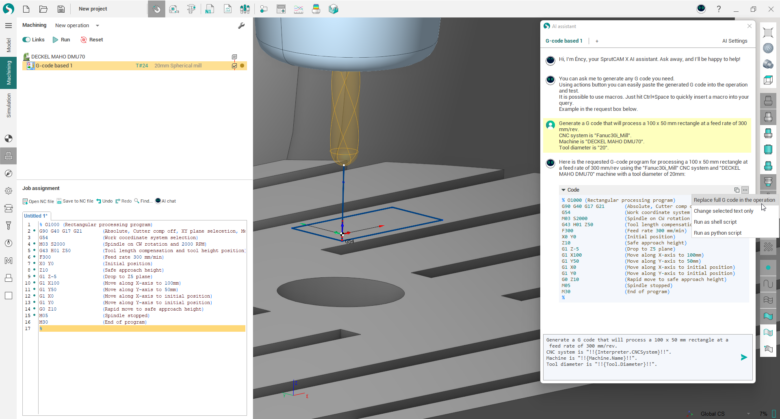
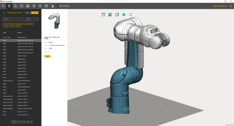
MecSoft Corporation, a developer of industry-leading CAM software solutions, announced the availability of VisualCAD/CAM 2021, the latest version of MecSoft’s complete standalone Computer Aided Design (CAD)/ Computer Aided Manufacturing (CAM) product.

Release highlights include:

–New and enhanced CAD features
–A New separately priced module for Adaptive Roughing in 3 Axis milling
–New Face-Top machining method in 2-½ Axis Milling
–Multiple Z-levels in 4 Axis Pocket Milling
–Additional tool axis controls for 5 Axis Continuous Milling
–Numerous features and feature improvements in 2 ½, 3, 4 & 5 Axis machining
–Programmable post-processors employing the Python programming language
–Other Productivity and User Interface enhancements
–Additional enhancements to the G-Code editor & Profile Nesting modules

MecSoft Corp.
mecsoft.com

Filed Under: CAD modeling, CAM Tagged With: mecsoft

Introducing hyperMILL 2021.1 CAD/CAM software suite

January 19, 2021 By Leslie Langnau Leave a Comment

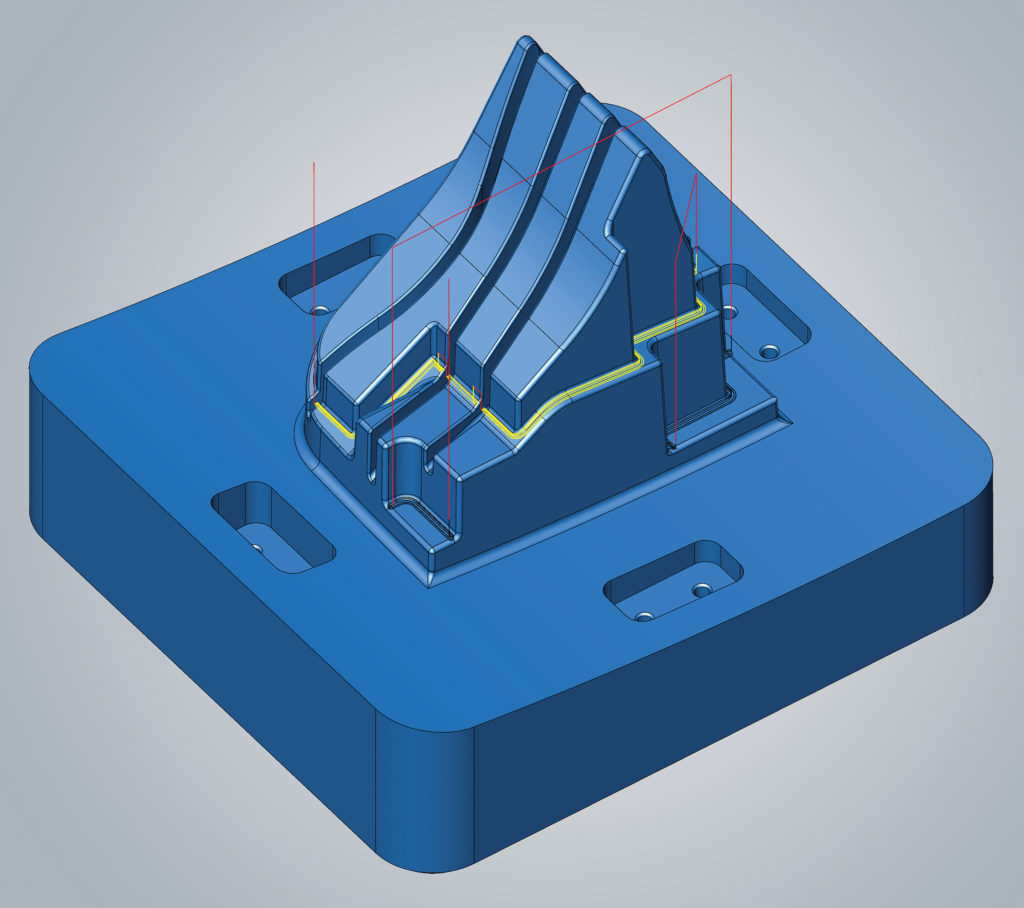
OPEN MIND Technologies AG, a leading developer of CAD/CAM software solutions, has introduced its latest hyperMILL 2021.1 CAD/CAM software suite which offers users new and enhanced features for efficient 3D, 5-axis and mill/turn machining. Key innovations include a new “Interactive Edit Toolpath” capability which enables toolpath editing after initial toolpath generation. Especially productive for optimizing tool and mold making, the new toolpath editing feature is easy-to-use, and offers programmers the flexibility to adapt toolpaths by trimming and removing sequences accordingly for component conditions.

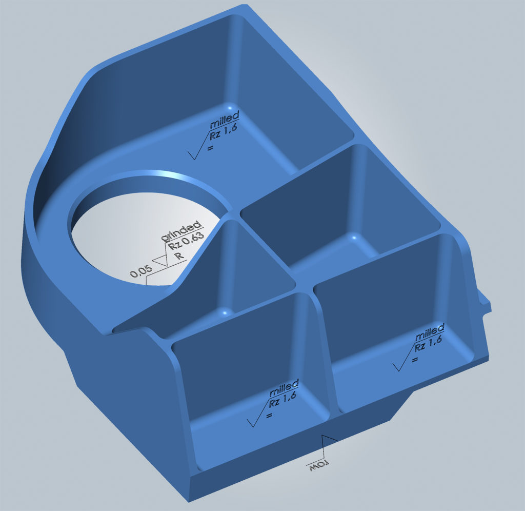
To streamline access to Product Manufacturing Information (PMI) and metadata, hyperMILL 2021.1 offers a new import function that retrieves face quality information and metadata when importing CAD data from neutral or native formats, and attaches data to the imported faces in hyperCAD-S, making the information available to hyperMILL and its machining processes.

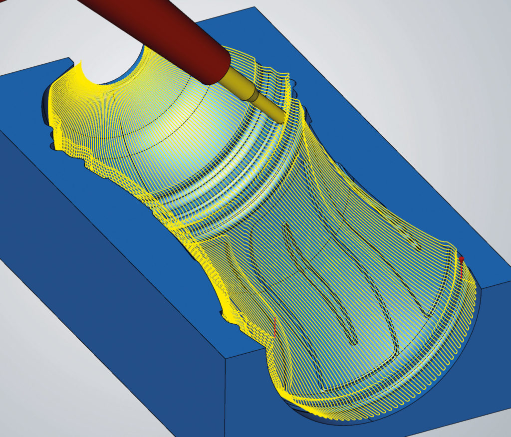
A new 5-axis Radial Machining strategy allows bottle shapes and similar cavities to be easily and efficiently programmed in hyperMILL, resulting in high-quality surface finishes. Using a new radial projection method, toolpaths are calculated quickly so that the most productive machining strategies can be applied. For optimal high precision machining, hyperMILL “High Precision Surface Mode” and “Smooth Overlap” strategies can also be applied when using 5-axis Radial Machining, ensuring the best surface quality and clean transitions.

For high-quality surface finishes and to simplify programming when flank and point milling blades, hyperMILL 2021.1 offers several enhanced Multi-Blade strategies. No longer do blade surfaces need to be ruled for accurate programming results. Using the enhanced strategies, any number of surfaces are permitted for the suction and pressure sides, making it exceptionally easy to extend blade surfaces. Fillets with a variable radius are supported in the latest version of hyperMILL. Also, for high accuracy, the enhanced Multi-Blade flank milling strategies result in smaller deviations on the suction and pressure side, and offer improved tool guidance along the upper boundary in the edge area.

hyperMILL 2021.1 provides a new SIMULATION Center for generic NC data in turning and milling operations. Modeled after the hyperMILL VIRTUAL Machining Center, the new, modern SIMULATION Center is integrated in hyperMILL, and offers an intuitive operating environment for faster simulation, independent collision checking and extensive analysis functions.

Additional new features in hyperMILL 2021.1 include a new, easy-to-use “XY Optimization” command for optimal 3D profile finishing. In the hyperMILL Mill-Turn Module, the high-performance mode has been integrated into a 3-axis simultaneous roughing strategy, combining the advantages of HPC and simultaneous turning. For the simplified alignment of components, hyperCAD-S has a new “Align Best Fit” machining command that allows like-geometry components to be aligned with one another using defined pairs of points.

OPEN MIND Technologies AG
www.openmind-tech.com/en

Filed Under: CAM, Company News, News Tagged With: openmind

Tech Soft 3D and OPEN MIND collaborate on CAM solutions

August 17, 2020 By WTWH Editor Leave a Comment

OPEN MIND Technologies AG, a leading developer of CAD/CAM software solutions worldwide, and Tech Soft 3D, a leading provider of engineering software development toolkits, announced that HOOPS Exchange, a CAD data access and reuse technology for manufacturing and architecture, engineering and construction (AEC) workflows, will be integrated into hyperCAD-S and hyperMILL to ensure that all CAD and Product Manufacturing Information (PMI) data are transferred seamlessly between applications.

“Tech Soft 3D is a trusted, reliable development partner who helps us implement specific requirements and accommodate customer requests,” said Dr. Josef Koch, CTO at OPEN MIND Technologies, AG. “This kind of responsiveness is critical in our industry, as well as interoperability with multiple CAD formats ‒ HOOPS Exchange is the leading product in this area and was an easy choice for us. We are very happy to be able to offer our customers the ability to work with any CAD file type now, without any loss of data integrity when sharing files.”

hyperMILL is a modular complete CAM solution for 2.5D, 3D, 5-axis, HSC/HPC, and mill-turning processes, and also includes special applications and highly efficient automation solutions. The CAM software provides technology-leading geometry analysis and tool path calculations. There are specialized routines designed for efficient programming and machining of these components on 5-axis milling or mill-turn machines. Robust CNC postprocessors are also provided to assure strong communication to machine tool controllers.

“Digital transformation is happening at lightning speed within the manufacturing industry and we are committed to helping our partners, such as OPEN MIND, keep pace with this rapid momentum,” said Lionel Vieilly, Product Manager at Tech Soft 3D. “Fast access to the full integrity of data, being able to use that data without the need for an additional translator, extreme performance with low memory usage – these are all paramount to quickly building robust, sophisticated 3D applications and we are proud to be the ones our partners look to as the gold standard.”

OPEN MIND Technologies AG
www.openmind-tech.com

Tech Soft 3D
www.techsoft3d.com

Filed Under: CAM, News Tagged With: openmind

What’s driving the automotive lightweighting revolution?

April 26, 2019 By WTWH Editor Leave a Comment

A perfect storm of social and regulatory changes, AI-driven generative design, and advances in additive manufacturing are bringing automotive lightweighting into the mainstream.

By Avi Reichental, CEO, Techniplas Digital

Since the widespread adoption of industrial technology began in the late 18th century, there have been only a handful of instances where a combination of social change, technological advancement and public policy converged to create the perfect environment to precipitate exponential change.

Today, we are witnessing just such a perfect storm in automotive lightweighting. The result will be a fundamental change in the way people and goods move from one place to another.

What exactly is driving the automotive lightweighting revolution, and how will its effects continue to emerge? To understand this, we need to take a deep dive into both the technological and social/regulatory sides of the equation.

Social and regulatory changes drive demand, but efficiency drives change
Environmental concerns like global warming are driving governments worldwide to demand changes from carmakers with strict emissions and fuel efficiency standards. In addition, consumers are beginning to take vehicle efficiency into account, and manufacturers are being forced to adapt.

But pure vehicle weight considerations are not the primary driving force behind the move to lightweighting. Manufacturers are prioritizing not only vehicular efficiency (of which weight is a key factor), but also overall manufacturing and operational efficiency.

Thus, social and regulatory demands have moved the ball into the manufacturing court. Yet what’s truly driving the lightweighting revolution and making it economically and ecologically viable to lightweight on a massive scale is the technological revolution that’s enabling the design and at-scale production of lightweighted parts.

AI-driven generative design is transformational
AI-driven generative design is lightweighting’s secret sauce.

The reason? Lightweighting by definition relies on either material substitution or reduction – achieving the same function with the same amount of a lighter material or less material. We’ve essentially reached the cost-benefit breaking point for material substitution, and thus the automotive industry has turned to material reduction for lightweighting. And material reduction is where AI-driven generative design truly shines.

AI-driven generative design transforms CAD from an electronic drawing board to a co-designer. Novel solutions created via generative design have shattered existing design paradigms, making the production of organically inspired structures – which can optimize materials usage and radically lower weight without compromising integrity – a reality.

Additive manufacturing brings generative design to life
Without the ability to produce amazing AI-driven designs at scale, the lightweighting revolution would be stuck in the laboratory. Thus, the final element of this “perfect lightweighting storm” is Additive Manufacturing (AM). Today, the automotive industry has the capability, tools, and experience to produce the complex and lightweight geometries created by generative design cost-effectively, rapidly, and at scale.

AM enables vehicle manufacturers to produce millions of the same parts or millions of one-of-a-kind parts. This turns conventional manufacturing wisdom on its head and provides automotive manufacturers a new degree of freedom that it has not previously experienced.

So where does lightweighting come in? The fact is that the components being created by generative design can only be practically manufactured using additive techniques.

Thus, the next generation of lightweighting is tied intrinsically to AM. And this is where things get fascinating. Because now, generative designs are being optimized for AM. Complex geometry is no longer a limitation, but an enabler. Tooling is no longer a must, and more parts can be combined into homogenous units at the design stage, without assembly – lowering part count and (you guessed it) weight.

The bottom line
Automotive manufacturers were early AM adopters – using it for design and prototyping for decades. They realized that this technology was a game changer, yet material performance, computing power and scalability were holding them back.

Today, processes are more cost effective, more scalable, and development cycles are shorter. Today, 3D-printed parts are being produced on a mass scale, and the foundation of traditional manufacturing is being rocked. With the addition of powerful and effective AI-driven generative design, automotive lightweighting today is limited less by technology than by pure imagination.

Filed Under: CAE, CAM, Make Parts Fast, Software Tagged With: techniplasdigital

hyperMILL 2019.1 expands finishing capabilities, process optimizations and more

February 4, 2019 By Leslie Langnau Leave a Comment

hyperMILL 2019.1 comprehensive CAD/CAM software suite has a range of new features and enhancements including an expanded Finishing Module in the hyperMILL MAXX Machining Performance Package, process optimizations such as a new thread milling module, a new function for reducing calculation times, tool database flexibility, and CAD optimization. See related videos for comprehensive details on the new functions in hyperMILL 2019.1.

5-axis prismatic Fillet Finishing

The 5-axis Prismatic fillet finishing function in hyperMILL MAXX machining enables the geometry and automatic inclination of barrel cutters to be applied similar to high feed cutters, using a plunging and pulling movement at extremely high feed rates. Maximum performance is attainable using conical barrel cutters (also known as arc segment or circle segment end mills). Ball or bull nose end mills can also be efficiently used.

Conical barrel cutter: finish prismatic fillets with an extremely high feed rate.

Improved surface finishes

The Profile Milling technique in 2019.1 has a new option that improves the quality of machined surfaces. Traditional CAM software processing uses a close-approximation mesh surface for machining calculations. A benefit of the mesh approach is to standardize CAM processing, even in cases when the design model has imperfections. OPEN MIND has implemented new techniques in hyperMILL 2019.1 for machining directly to the model surface, which has substantially improved surface finishes.

hyperMILL 2019 high precision surface finishing mode (right) compared to conventional mode on left.

Enhanced process optimizations

Among the process improvements in 2019.1, the updated Thread Milling module is easy to program and supports a number of thread milling types, while simplifying selection and milling direction options.

Also new to 2019.1 is the elimination of cycle recalculation requirements, improving processing speed. Recalculation cycles are no longer required when job I.D. numbers are changed or when fixture positions change. In addition, for improved tool management users now have the option to individually expand the tool database in hyperMILL 2019.1, allowing the ability to store order numbers, pricing and tool life detail.

CAD optimized for CAM

hyperCAD-S in the 2019.1 suite, which is optimized for CAM requirements, includes polyline management, enabling CAD functions such as lengthening or shortening to be applied by the polylines element type. Polylines can also be machined similar to all other elements, with trim, join, orient or select.

OPEN MIND Technologies AG
www.openmind-tech.com.


Filed Under: CAM, News Tagged With: openmind

Is SolidWorks CAM Better Than an Integrated System?

December 15, 2017 By Leslie Langnau Leave a Comment

When the engineering software vendor announced it was moving from integrated CAM to a total CAD/CAM solution industry watchers took note.

Jean Thilmany, Contributing Editor

For engineers and design companies, it’s not difficult to find integrated computer-aided design and computer-aided manufacturing technologies. Yet, the announcement of SolidWorks CAM, released in October as a SolidWorks 2018 add-on, has created a small buzz in engineering technology circles.

Why?

It’s no secret that engineers struggle to create designs that are easy to manufacture while machinists complain about receiving unworkable CAD models.

An imperfect fit

CAM software uses the CAD models to generate the toolpaths that drive computer numerically controlled manufacturing machines. Engineers and designers who use CAM can evaluate designs earlier in the design process to ensure they can be manufactured, thus avoiding product costs and delays.

Without CAM, manufacturers can be on their own when programming machines to make the CAD model. And not all those who design in CAD enter design features into CAM to control the machine tools. Without CAM, manufacturers use the CAD design to program the tools themselves.

SolidWorks CAM could create codes for the end machine used for manufacturing.

“The general idea has been that engineers design something and then the manufacturing people eventually figure out how to manufacture it,” says Sandesh Joshi. “With integrated CAM, they’re not as disconnected as that, but there’s still a disconnect. This SolidWorks tool could close that disconnect.”

Closing the CAD/CAM disconnect

Joshi is chief executive officer at the CAD outsourcing firm Indovance. Previously, he spent six years on the SolidWorks research and development team.

The SolidWorks offering could ramp up the number of CAM users by making the tool available to more engineers and designers, Joshi says. The SolidWorks 2018 release marks the first time that SolidWorks is providing the CAM product as part of its design solution.

SolidWorks CAM is “powered by” CAMWorks, in the vendor’s parlance. Before the October release, CAMWorks, from HCL Technologies, was one of many third-party CAM tools available for integration with the vendor’s CAD program.

Of course other CAD vendors offer integrated CAD and CAM solutions.

Siemens PLM Software, for example, also offers CAMWorks as an embedded solution within its Solid Edge CAD program. NX CAM, also from Siemens PLM Software, is integrated with other NX solutions, which allows NC programmers and manufacturing engineers to associatively access design, assembly and drafting tools in a one part-manufacturing environment, according to that software maker. And CAM features are integrated into the Fusion 360 design tool from Autodesk.

But rather than taking on two separate software solutions, CAD and CAM can act as one system within SolidWorks CAM, Joshi says. That could make CAM easier and more straightforward to the software’s users.

The solution is fully integrated with SolidWorks so users need not leave the familiar SolidWorks environment, says Mike Buchli, senior SolidWorks product and portfolio manager. It supports feature recognition and can generate machining operations directly from native SolidWorks files or from imported data. Toolpaths are automatically updated based on changes to the model.

If SolidWorks 2018 engineers and designers feel they’re working within one integrated system–rather than two separate but connected software systems—they might begin to automatically use CAM and to consistently consider manufacturability as they design the product, he adds.

The vendor’s tool opens the way toward making CAM ubiquitous on engineers’ desktops, much as 3D CAD is now more-or-less used across an industry that once relied on 2D drawings, he said.

The part process from CAD to machining will never be a “one-click process,” Joshi says. But it certainly can become more streamlined through the use of a common CAD and CAM system.

“The difference is engineers would be using CAM as they design so manufacturability is easier,” he says.

“When we build assemblies, we have clash detection. Similarly, CAM gives us red flags for manufacturability right at he design stage, saves a lot of time and money,” Joshi says. “Today all design engineers don’t necessarily deal with CAM, so having access to that will help engineers design for manufacturing way ahead in the product design cycle.

SolidWorks CAM holds the potential for both designers and manufacturers–the possibility of a key to the elusive quest for CNC standardization.

“Some kind of machining cannot be done, and if that’s true it’s better to change the design right away rather than during the manufacturing process,” he says.

The system offers tools to validate and improve part and tool designs, including part-manufacturability checks and tool-motion simulation, Buchli says.

In a blog post introducing the tool, he outlined other benefits, such as the capability to:

–Recognize certain types of geometry to understand how those features will be manufactured, and how much it will cost to manufacture.

–Read tolerances and surface finishes and make decisions about how to manufacture the product

–Automatically apply best manufacturing strategies so manufacturing processes faster and more standard

–Automate quoting and compare it to traditional methods to ensure all aspects of the part are accounted for ahead of time

Fewer codes in the future?

The introduction of SolidWorks CAM holds the potential for another big benefit for both designers and manufacturers: the possibility of a key to the elusive quest for CNC standardization, Joshi says.

If the CAM tool becomes popular among SolidWorks users, Joshi can envision a day when the software automatically produces the G-codes that drive the machines that manufacture the part.

Right now, manufacturers struggle to drive their machining processes directly from their design software. The CAD systems don’t “speak the language” of various machines such as cutters and laser cutters, CNC mills and lathes.

“There are different flavors of G-codes depending on the CNC controller,” Joshi says. “The basic commands and operations generally will work on all machines but there are particular specialties and differences.

If SolidWorks CAM becomes widespread with designers who already use the vendor’s CAD program, the vendor “could potentially create codes for the end machine used for manufacturing,” Joshi adds. “The designer may not have to worry about that up front, but it makes manufacturing a lot smoother.”

With enough popularity, others will adopt those same end-machine codes, he says, creating a more-or-less-standard manufacturing-machine programming code.

And he knows of what he speaks. Currently, designers often rely on machinists and production engineers to develop strategies to effectively make the part.

“Job shops and manufacturing generate G-code for their CNC machine tools based on the CAD models they receive,” Joshi says.

Technologists at his company help interpret “on the back end” how to machine CAD designs, he says. He sees the issues manufacturers have with CAD designs.

“These companies get models from anybody and everybody and they don’t necessarily have all the types of CAD software. So they’re importing raw data rather than inclusive parametric models,” Joshi says. “It still works, but it’s more work.

“If the process is more integrated from end to end, it’s more likely to be seamless,” he adds. “If something has to be changed or modified it can be done quickly rather than going to engineering and coming back and being modified for machining.”

At SolidWorks World 2017, held last February, at which SolidWorks CAM was teased, Buchli related the benefits integrated CAD and CAM can mean for a company, specifically CP-Carillo, of Irvine, Calif., which makes pistons and connecting rods for high-performance race vehicles. The company saw a “significant increase in throughput” when using the then-integrated SolidWorks and CAMWorks, Buchli said in February.

Before using CAMWorks, the manufacturer input SolidWorks model geometry into the Mastercam program to create toolpaths and generate G-codes.

“We programmed each custom piston order manually, slowing down manufacturing,” says Karl Ramm, former CP-Carillo senior technology manager and project developer.

“Each job would take about 10 minutes for non-complex pistons and up to 40 minutes for complex pistons–and that’s programming time alone,” Ramm adds.

When the company brought in the integrated CAD and CAM solution, “custom orders that took days to design and program went down to hours,” Ramm says. “What used to take five to 15 minutes takes seconds now.”

The time-savings comes because the process is automated. Designers load custom criteria into a database and launch SolidWorks. The design application automatically pulls in that criteria and the designer can then create the new piece, which it transfers into CAMWorks. The CAM program then automatically generates new toolpaths and posts them to CNC machines in the shop, Ramm says.

The capability to share that kind of design and programming knowledge between engineering and manufacturing speaks to one of the biggest benefits of an integrated CAD and CAM system, Buchli says.

Another benefit is consistency of workflow. At CP-Carillo, custom orders always follow the same path. Design engineers and manufacturers know what’s expected of them when creating and manufacturing custom orders, Buchli adds.

SolidWorks CAM is much too new to see if any of Joshi’s predictions about standardization and popularity will play out.

But product lifecycle management consultancy CIMdata Inc. says it welcomes the decision to package and offer SolidWorks CAM.

“It protects the investment of CAMWorks users and adds proven CAM capabilities to SolidWorks,” according to a CIMdata statement.

While it remains to be seen if SolidWorks CAM is a step beyond the type of integrated CAD and CAM systems that exist today, Joshi and CIMdata are certain the engineering software vendor has taken a step in the direction down which the industry must travel to iron out disconnects between engineering and manufacturing and to save manufacturers costs and development time in the future.

Dassault Systemes SolidWorks Corporation
Solidworks.com

Filed Under: CAD Package, CAM, Featured Tagged With: dassaultsystemes

Tebis America announces the latest Release 5 of its Version 4.0

November 27, 2017 By Paul Heney Leave a Comment

Tebis

TEB-143A Caption: For this complex part, Tebis Version 4.0 Release 5 automatically selects the total of 705 tools for collision-free machining of the 270 features in just two minutes—a time savings of 80% in comparison with the previous version.

Tebis America has announced the latest Release 5 of its Version 4.0. Tebis has especially optimized the performance of its software with the current Version 4.0, Release 5. This helps users significantly accelerate their processes without functional restrictions. Examples include machine simulation, working with tool sets, searching for tools in feature machining or exchanging tools in the Job Manager.

Over the years, Tebis has continued to expand and modernize the functionality of its software. With the new release, NC programming is now largely automated based on templates with process libraries that enable fast and reliable procedures and processes. Users can also easily edit large and complex parts with Tebis.

Convenient and powerful technologies place large demands on computing resources and can easily affect performance. Tebis has identified that the heaviest loads occur in specific processes…the so-called bottlenecks that can result in long waiting times as well as heavy use of resources and conflicts. The Tebis developers then adapted the system to optimize the use of all available memory. Multi-core technology relying on parallel processing was simultaneously integrated.

The extended parallel processing now used saves significant time, especially in the calculation of NC programs for re-roughing. Parts can be loaded, shaded and saved with time optimization.

Tebis America
www.tebis.com

Filed Under: CAM

MecSoft announces RhinoCAM 2015

March 5, 2015 By Jennifer Calhoon Leave a Comment

MecSoftMecSoft Corporation has announced the availability of RhinoCAM 2015, a major version release for MecSoft’s integrated CAM solution for Rhino. RhinoCAM 2015 includes four CAM modules MILL, TURN, NEST, and ART, each of which run completely integrated inside the Rhino 5 CAD program.

All CAM modules were significantly enhanced and improved in this 2015 release to provide customers with a powerful and complete manufacturing platform. Highlight of the release include the Hole Feature Detection and Automatic Machining of Hole Features functionality. Please click on the buttons below to learn more.

MecSoft
www.mecsoft.com

Filed Under: CAD Hardware, CAD Package, CAM, Rhino Blogs Tagged With: mecsoft

OPEN Mind Releases hyperMILL 2014.2 CAM Software

January 22, 2015 By Barb Schmitz Leave a Comment

OPEN MIND has released the newest version of its CAD/CAM software, hyperMILL 2014.2, which includes several new functions in addition to enhancements to existing functions. The company’s hyperMILL software was touted in market research firm CIMdata’s NC Market Analysis Report 2014 as one of the best CAM systems on the market. In addition to a key extension for solid modelling in hyperCAD-S, the CAD part of the system, hyperMILL 2014.2 features a range of improvements for CAD programmers and machining.

hyperMILL 2014.2 offers a key extension for solid modelling in hyperCAD-S, the CAD part of the system.

Let’s look at what’s new in this release.

3D shape Z-level finishing

When it comes to Z-level finishing, CAD systems usually simply follow the X and Y coordinates. If the bottom surface is curved, the milling result is not optimal, making it necessary to perform a number of rework machining steps. A new function for 3D shape Z-level finishing makes it possible to reference curved bottom surfaces, after which the milling paths are aligned. As a result, the milling tool nestles optimally along the boundary edge between the bottom and the wall. All intermediate levels are offsets of the bottom plane.

3D shape Z-level finishing allows curved bottom surfaces to be referenced.

The OPEN MIND soft bounding concept is also integrated into this new function, which ensures that the boundaries to adjacent surfaces are calculated more precisely and that sharp outer edges are machined more smoothly. User benefits include an optimised finish and reduced programming and machining times.

3D rest material machining

The open, deep, steep and flat areas of cavities can be machined in one job with collision avoidance. The rest material areas that are recognized during the collision avoidance are transferred automatically to the subsequent job. To this end, optimal tool selection and positioning once again take place. For example, a longer tool or modified position. This process is repeated until the required contour is achieved. Work here has been greatly simplified for CAM programmers.

hyperMAXX improvements

hyperMAXX, the cutting (HPC) module for hyperMILL, was also improved in some areas. This includes plunging the milling tool into the material at pre-drilled holes, which saves ‘ramping-in’ of the milling tool at the start of machining. The greatest advantage of this method is that it protects tools, particularly in materials that are difficult to cut. The machining process is also collision-checked. Furthermore, it is now possible to select a zigzag mode in hyperMAXX. This mode is particularly suited to machining large workpieces, as it prevents time-consuming repositioning movements, thereby significantly shortening machining times.

2D plunge milling

With 2D plunge milling, another new feature, material is removed solely by plunging a milling tool. The new cycle is suitable for both roughing and finishing. The advantage here once again lies in the fast machining and particular suitability for materials that are difficult to cut.

For more information about hyperMILL 2014.2, check out there company’s web site here.

Filed Under: CAM, News Tagged With: OPEN MIND Software

Using simulation to guide product design

December 10, 2014 By Barb Schmitz Leave a Comment

by Barb Schmitz, Senior Editor

Products vary in size, shape, complexity, and usage so it’s hard to generalize anything about product design. The processes by which companies create new products, however, are typically the same. First they define what the product will do (product specifications), and then they capture all of the things that will define the product (design intent).

Once that has been agreed upon, the design team creates detailed designs and tests these burgeoning product ideas to see if they actually behave in the real world the way in which they are designed. When or if they don’t, changes are made to the design and they are tested again. This testing was once conducted using physical prototypes, which is both costly and time-consuming to conduct.

Today this process is very different and more efficient, thanks to virtual testing using simulation software. Digital models are now put through their paces in virtual prototyping environments using simulation software, such as finite element analysis (FEA) or computational fluid dynamics (CFD). Often later in the cycle, physical prototyping testing is used to confirm the simulation results so product designs can be moved onto manufacturing.

Simulation speeds up decision-making
Every step of the product development process is littered with questions, most of which can be answered in multiple ways. How big should it be? How strong does it need to be? Can we reduce its weight? If we reduce its weight or use less material, will it affect its strength? Can we use a different material? Answering these questions as accurately and quickly as possible has a direct impact on both the cost and speed of product development.

After all, engineering is all about asking many questions, making mistakes, changing things, and on and on until you arrive at an optimum solution or design. Calculations, prototypes, and analysis are all tools that provide guidance to engineers as the design moves through the design cycle. Most product geometries are too complex for hand calculations and physical prototypes are costly and built too late in the cycle to be used to optimize designs upfront.

Simulation has emerged as the best way to do all of that quickly and at least cost—both in terms of actual cost and time to market. Originally conducted later in the design process, there is abundant evidence that suggests that products should be simulated throughout the design process. In fact, most agree that simulation should start at the very beginning of the design cycle, during concept development, to quickly vet the ideas being considered and put designs on the best path.

How analysis is used in product design
The shift from simulation tools being used for product validation to an essential part of upfront design requires a paradigm shift involving changed processes, new tools and new ways of thinking for engineers.

Engineers are increasingly turning to simulation early in the design cycle, during concept development. At this stage of design, the product geometry is basic so multiple iterations using simulation can be done quickly so product designers can quickly answer ‘what if’ iterations and move forward with the best design alternative.

“With product design, it’s important to get off to a very good start,” said Bernt Nilsson, senior vice president of Marketing at COMSOL. “When you’re implementing simulation, you want to start in the very early stages, or conceptual design phase. At this stage, when you want to get a basic proof of concept going, you want very simple models. That means you’re using very basic geometry, avoiding including too many details that would slow down the analysis.”

Having some level of integration between CAD and analysis enables engineers to test ideas, adjust designs, explore, and verify to confirm that designs are on the right track, minimizing the risk of flawed designs moving forward when changes are most costly. In other words, design-integrated analysis enables design teams to explore more design variants in less time.

Who should be using simulation tools?
The reality is that simulation tools are as a whole being underutilized at most companies. Possibly the problem is more cultural, than technological. Many engineering managers have not mandated or allowed a process change that leverages simulation. In addition, the question as to who should be using these tools continues to be debated.

Mentor-Graphics-FloEFD-software
Mentor Graphics’ FloEFD software provides a unique range of capabilities required for challenging lighting applications and types of lighting, including LEDs.

A recent CIMdata report cites complexity as one of the underlying issues preventing more widespread adoption. To make simulation software easier to use, several vendors developed simulation packages that are directly integrated with CAD systems. By and large, however, these CAD-integrated simulation software were also not widely embraced by the industry.

Many believe this is due to the fact that not many engineers and product designers–for whom these products were developed–understand the underlying fundamentals of simulation. According to the CIMdata report, “democratization is about simplifying the application of the tools and making them more widely available. It is not for these powerful tools to be used by those who do not understand the product and engineering issues.”

Mentor-Graphics-FloTHERM-XT
By making it easier and faster to mesh complicated shapes and geometries, Mentor Graphics’ FloTHERM XT software democratizes the use of thermal simulation.

Many vendors maintain that only simulation or R&D experts should use simulation tools; that these tools should not be “dumbed down” for engineers to use. Others maintain that simulation will not meet its potential in terms of benefits to the design process until it is widely embraced by design engineers.

Simulation tools are typically offered as standalone software or as CAD-integrated software. With the latter, the simulation tool is launched directly from within the CAD environment, the simulation uses native CAD geometry, and many of the pain-provoking steps of traditional simulation—such as meshing—has been automated. There are benefits to both approaches.

“Fully integrating simulation capabilities within the native design environment of mechanical design engineers provides them easy and direct access to the benefits of up-front simulation throughout their design stages,” said Robin Bornoff, PhD, Market Development Manager, Mentor Graphics Mechanical Analysis Division. “Whether it’s Creo, CATIA V5 or Siemens NX, being able to simulate a design without suffering the pain of data interoperability with standalone simulation tools puts simulation directly under their control.”

Several CAD vendors, such as SolidWorks, contend that simulation tools should be embedded in the CAD software to best enable engineers to leverage their use. “Nowadays, all product engineers can leverage their mechanical engineering knowledge to design better products using 3D CAD and simulation tools,” said Delphine Genouvrier, Senior Product Portfolio Manager, SolidWorks Simulation. “With CAD-embedded simulation, every engineer involved in product development can apply corrective action on the design that is triggered by the insights provided by the simulation results.”

SolidWorks-CAD-software
By tightly integrating SolidWorks CAD software with powerful simulation capabilities, users can test against a broad range of parameters during the design process, such as durability, static and dynamic response, assembly motion, heat transfer, fluid dynamics, and plastics injection molding.

Other vendors have focused on automating functions within their software that enable engineers and product designers to use simulation tools without having the domain expertise of experts. “CFD simulation has historically required knowledge of the underlying algorithms to be able to select appropriate options for a given application,” said Bornoff. “Automating such choices liberates the design engineer from this pre-requisite, allowing them to focus on their given design challenge and not the numeric of the tool employed.”

Bridging the gap: how engineers and analysts can work together
Some highly complex design scenarios require specialized tools, such as multiphysics simulation software, which typically requires the expertise of R&D and simulation specialists. This, however, doesn’t mean that simulation results are not of use to product designers and engineers. High-end simulation developers have worked hard to create capabilities that facilitate this interaction between the simulation specialists and the product engineers. Providing better ways for these two groups to collaborate enables the design process to be iterative and benefit from insights provided by simulation results.

“You have this interaction between the simulation expert and the design engineers so you need tools that support that collaboration. We’ve invested a lot into making it easier to combine COMSOL with CAD, because it’s crucial to get that right,” said Nilsson. “Our LiveLink products enable you to take a large CAD assembly and combine or link it with your simulation in COMSOL. You have this bidirectional link so when you make a change to the CAD geometry, it is automatically updated in COMSOL.”

COMSOL-model-of-an-air-filled-shell
This COMSOL model of an air-filled shell and tube heat exchanger shows water flowing through the inner tubes. Simulation results reveal flow velocity, temperature distribution, and pressure within the vessel.

When CAD-embedded simulation tools are being deployed, the interaction between the engineers and the specialist looks slightly different. Engineers deploy the simulation tool for optimization of design concepts and analysts use the tool later to do final validation.

“Product engineers can detect early potential product issues, improper behavior and compare their design ideas with ‘what if’ scenarios,” said Genouvrier. “So when the analyst receives the product later in the process, it has already been optimized and tested for product performance so they can then focus on final validation or complex simulations, using their expertise in advanced analysis rather than doing product optimization. This is a win-win situation for the entire company.”

The reality is that at each company, simulation experts are small in number compared to the number of engineers so careful consideration must be made in terms of how to make best use of their time.

“Analyst experts are few and far between in the context of the number of design iterations that are considered during the design process,” said Bornoff. “The question is how best to utilize their competence. ‘Turning the handle’ to simulate each design iteration can and should be done by the designer. When a problem is identified, then that is the time to involve the analyst. Not because they have experience in using an ‘advanced’ simulation package, but because they have the domain expertise to be able to identify and recommend a remedial design solution.”

CAD-embedded-CFD
By using CAD-embedded CFD, engineers can optimize the proposed design immediately and inside their preferred CAD environment. They compare configuration and parametric study capability inside FloEFD for Creo enables engineers to understand the influence of a variety of changes in the geometry or boundary conditions on the results without leaving the Creo tool.

Design culture must adapt to maximize benefits
In order to truly maximize their investment in analysis tools, companies need to stop propagating the idea that simulation can’t drive design; it can only validate them. Without a process change, designs being validated digitally are the ones that would have been validated through physical prototyping. So where’s the value add?

Better user training is also in order. Users need to better understand what simulation results are telling them, either about the design or about the quality of the simulation. Additional training on input properties, material properties and failure mechanisms will empower them to make better decisions and look further to find the optimal configuration

Whether simulation tools are being used by specialists or by product engineers—or both—simulation holds the key to reduced physical prototyping, higher-quality, more optimized products, and faster design cycles. The key being that design optimization must happen early in the design cycle when changes can still be made without significant rework, lost cycle time or significant expense.

Reprint info >>

COMSOL
www.comsol.com

SolidWorks
www.solidworks.com

Mentor Graphics
www.mentor.com

Filed Under: CAE, CAM, CFD

  • Go to page 1
  • Go to page 2
  • Go to Next Page »

Primary Sidebar

3D CAD NEWSLETTERS

MakePartsFast

Follow us on Twitter

Tweets by 3DCADWorld

Footer

3D CAD World logo

DESIGN WORLD NETWORK

Design World Online
The Robot Report
Coupling Tips
Motion Control Tips
Linear Motion Tips
Bearing Tips

3D CAD WORLD

  • Subscribe to our newsletter
  • Advertise with us
  • Contact us
Follow us on Twitter Add us on Facebook Add us on LinkedIn Add us on Instagram Add us on YouTube

3D CAD World - Copyright © 2021 · WTWH Media LLC and its licensors. All rights reserved.
The material on this site may not be reproduced, distributed, transmitted, cached or otherwise used, except with the prior written permission of WTWH Media.

Privacy Policy