• Skip to primary navigation
  • Skip to main content
  • Skip to primary sidebar
  • Skip to footer

3D CAD World

Over 50,000 3D CAD Tips & Tutorials. 3D CAD News by applications and CAD industry news.

  • 3D CAD Package Tips
    • Alibre
    • Autodesk
    • Catia
    • Creo
    • Inventor
    • Onshape
    • Pro/Engineer
    • Siemens PLM
    • SolidWorks
    • SpaceClaim
  • CAD Hardware
  • CAD Industry News
    • Company News
      • Autodesk News
      • Catia News & Events
      • PTC News
      • Siemens PLM & Events
      • SolidWorks News & Events
      • SpaceClaim News
    • Rapid Prototyping
    • Simulation Software
  • Prototype Parts
  • User Forums
    • MCAD Central
    • 3D CAD Forums
    • Engineering Exchange
  • CAD Resources
    • 3D CAD Models
  • Videos

3D CAD Package Tips

COMSOL completes the working environment for modeling and simulation projects with the Model Manager Server

April 26, 2022 By WTWH Editor Leave a Comment

COMSOL announces a major update to the COMSOL Multiphysics software version 6.0. The update builds out the Model Manager server with a web interface — an asset management system — to make it easier for COMSOL users and nonusers alike to manage models, simulation apps, and supplementary and auxiliary files.

COMSOL Multiphysics: from building models and apps to managing simulation projects
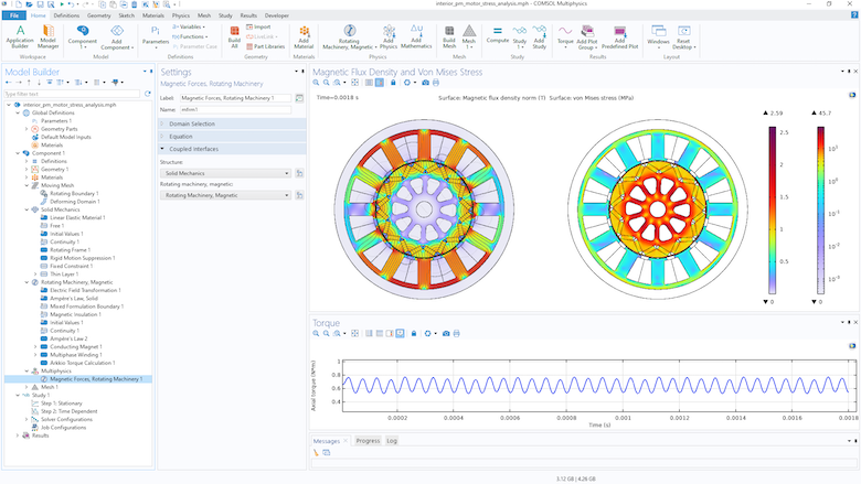
Through two decades of development, COMSOL Multiphysics evolved from a software that solved partial differential equations to one that defines the nature of multiphysics modeling: being able to build models with any combination of physics phenomena via the Model Builder. Thereby, engineers versed in the underlying physics and using software to build models began using COMSOL Multiphysics across technology-driven industries, academia, and research organizations for modeling and simulation. Next, COMSOL introduced the Application Builder and concept of simulation apps to expand the realm of who could access simulation to include those who had not traditionally been able to work with models and simulations.

Today, COMSOL completes the environment for managing modeling and simulation projects for product and process design through the recently introduced Model Manager and the Model Manager server with its accompanying asset management system.

About the Model Manager Server and its Asset Management System
Released in December 2021, the Model Manager allows you to:

–Search through models for particular parameter names and feature strings.
–Track model development through version control with model comparison and merging capabilities.
–Upload, link, and administrate supplementary and auxiliary files to a modeling and simulation or development project.

A screenshot from the Model Manager UI within the COMSOL Desktop® that shows the different databases that have been set up to administrate and structure models, along with branching, version control, feature lists, and the folder system used to manage the simulation. The model tree of a selected model can be previewed without opening the model.

The Model Manager has now been complemented by the Model Manager server’s asset management system, which is accessible through a web interface. In the asset management system, an asset can be considered as a container for links to your model versions, attached supplementary and auxiliary files, as well as various custom metadata fields. With the asset management system, you can itemize assets through model and app files, adding abstracts, setting permissions, and even include thumbnail images of the model at hand.

“As an extension of the COMSOL Multiphysics® simulation platform, the Model Manager server’s asset management system is useful for administrating and managing your models, apps, and simulations in a corporate network environment set up to your own liking,” says Sr. VP of Sales Phil Kinnane. “This could be project-based, model-based, team-based, or similar, according to how you want your organization to structure and organize such work.”

A web interface of the Model Manager server asset management system that shows different assets and metadata (asset type, author, distribution, etc.)


Clicking into an asset allows you to add files and metadata (abstract, thumbnail image, product requirements, etc.)

A collaborative environment to cover all elements of an organization
The Model Manager server is a database system that can be managed from either the COMSOL Desktop or a web-based UI. A local installation of any license type of COMSOL Multiphysics with the Model Manager and a local database is usually the initial step for a modeling engineer to acclimatize themselves to how this system can be best used within their organization. From there, full deployment can occur by installing the Model Manager server on a central server. Local installations of COMSOL Multiphysics can connect to the central server with the Model Manager server. “I think organizations will start by moving the tens and hundreds of COMSOL models they have been developing over the years to their asset management systems as a communal model library,” adds Kinnane. “Instead of chasing down the many engineers using the software for different purposes, they can now find and search through those models as a centralized repository instead.”

The full power of the Model Manager Server
COMSOL CTO Ed Fontes describes how the Model Manager server will take an organization’s simulation-driven project to the next level: “The true power of the Model Manager is not only in its ability to manage your simulation data, but in being able to version control and audit your actual model-building process.” He adds, “there are a number of simulation data management systems out there, but COMSOL has focused the Model Manager on the model-building process, such as to easily browse through the model tree of certain models or search for specific features like domain settings, boundary conditions, or study types to revisit, update, or even reuse.”

Internal or external customers may use the database system to keep track and use results from a project. They may also use simulation apps and provide feedback about their measurement and test data by uploading them and reports to the relevant asset. And, of course, contributors on the model development can also add their auxiliary data, such as CAD files and specifications, to the project. “In all,” says Fontes, “the Model Manager server and asset management system truly provide the complete working environment for modeling and simulation projects.”

COMSOL
www.comsol.com

Filed Under: COMSOL Tagged With: COMSOL

Siemens adds intelligence-based design to Xcelerator portfolio with latest release of NX

February 14, 2022 By Leslie Langnau Leave a Comment

Siemens Digital Industries Software today launches the latest release of its NX software, part of the Xcelerator portfolio of software and services. The latest release of NX software leverages advanced technologies, such as artificial intelligence (AI) and advanced simulation capabilities, while continuing to invest in significant productivity and capability enhancements to enable its community of designers, engineers and manufacturers to innovate more quickly.

Designing in the context of the full product assembly gives confidence in component validity and allows the impact of design changes to easily be understood

“In the latest revision of NX, Siemens Digital Industries Software has smoothly woven topology optimization design from requirements, through to component generation, additive manufacturing, and final machining by leveraging their convergent modeling and automated model-based definition authoring for PMI generation together with task-based collaboration.” said Dr. Ken Versprille, Executive Consultant, CIMdata. “Users will welcome the effortless user interface that guides stakeholders through each step of the process.”

Highlights of the new release of NX software include:
• The new NX Topology Optimizer helps to create parts based purely on functional and design space requirements, resulting in fully editable convergent bodies that would be almost impossible to design and engineer manually. Inevitable design changes can be quickly made, optimizations and any downstream features updated automatically – saving time, effort and maximizing reuse of intelligence design and engineering data.
• The Design Space Explorer combines design space exploration with generative engineering to help designers automatically optimize a design against multiple objectives. Design engineers define the optimization problem with all parameters, constraints, and objectives in place and NX uses Simcenter™ HEEDS™ software to conduct multi-objective parameter optimization, providing the designer immediate set of viable design alternatives to consider that would have otherwise required a simulation specialist.
• Increased Artificial intelligence (AI) & machine learning (ML) in the Selection Prediction and Select Similar commands uses shape recognition to quickly identify geometrically similar components, while the NX Voice Command Assist allows the user to invoke commands, navigate multi-level menus and operations as well as teach the system words or phrases to carry out common tasks. Ask NX “Have we done something like this before?” and it will carry out a Shape Search using Siemens’ Geolus® technology.
• Lattice structures within NX can now be optimized using Siemens’ Simcenter 3D simulation to derive the optimal lattice structure in a singular environment – eliminating the multiple design analysis steps required traditionally. Elsewhere, Part Orientation Optimization brings nesting of parts (and their associated supports) within a machine build area along with integrated cloud-based orientation optimization processes to find the optimal build orientation for reduced thermal distortion. Siemens continues to deliver advanced capabilities in additive manufacturing that are designed to help our customers optimize their overall design and manufacturing processes.

New manufacturing techniques like Additive Manufacture can be automated to build in process intelligence such as support structure design.

“With each new release of NX, Siemens is pushing the barriers of what product development systems are capable of,” said Bob Haubrock, Senior Vice President Product Engineering Software, Siemens Digital Industries Software. “Our shift to continuous releases of NX is proving incredibly popular with our community – enabling us to deliver  capabilities more quickly than before. This means providing access to new tools and technologies so they can be applied to our customers’ design, engineering and manufacturing challenges to help them overcome them more quickly. We continue to improve the core tools our customers rely on every day, with over 1,200 customer enhancement requests delivered in this release.”

Siemens Digital Industries Software
siemens.com/software

Filed Under: Siemens Digital Industries Software Tagged With: Siemensdigitalindustriessoftware

COMSOL announces event series introducing Version 6.0 of COMSOL Multiphysics

January 20, 2022 By WTWH Editor Leave a Comment

COMSOL, the maker of the COMSOL Multiphysics simulation software, has opened registration for COMSOL Day: Version 6.0, a series of online events held around the world for the computer-aided engineering (CAE) market. Starting on January 27, there will be four events to introduce COMSOL Multiphysics version 6.0 to a global, multiphysics simulation community of innovators and managers in research and product development.

These events showcase how new simulation and collaboration tools introduced with COMSOL® version 6.0 will advance simulation-driven product development. Speakers from COMSOL will present major news and offer a closer look at new functionality in version 6.0, such as the Model Manager, a new simulation data management workspace in COMSOL Multiphysics.

“We are truly excited about the Model Manager,” says Phil Kinnane, senior VP of sales at COMSOL. “It takes us and the CAE industry to the next level in integrating simulation in product development. When mentioning this new tool to some of our experienced, ‘power users’, they immediately recognized how important it will be for their current COMSOL Multiphysics simulation projects.”

Sessions focusing on the Uncertainty Quantification Module will provide an introduction to using sensitivity analysis, reliability analysis, and uncertainty propagation in multiphysics simulations. Software updates for specific application areas are covered in separate, dedicated sessions, such as “Electromagnetics” and “Fluid Flow & Heat Transfer” to name two. Similarly, core functionality news is covered across several dedicated sessions, including “Summary of Major News”, “Geometry and Meshing”, and “Optimization”.

“COMSOL Day attendees have the opportunity to interact with COMSOL engineers during live sessions and ask software developers and support engineers questions directly,” says Lauren Sansone, marketing and events director at COMSOL. “The events bring a live stream of sessions throughout the day, and it is easy for attendees to choose if they want to participate in the entire program from start to finish or only attend specific sessions.”

The COMSOL Day: Version 6.0 event dates are:

January 27 (U.S., 11 a.m. EST)
February 3 (Sweden, 10 a.m. CET)
February 10 (India, 10 a.m. IST)
February 24 (China, 1 p.m. HKT)

Participation from any region at any of the events is welcomed. Please note that the sessions hosted by the COMSOL offices in the U.S., Sweden, and India will be conducted in English, while the event hosted by the office in China will be in Chinese.

These events are open to all, and attendance is free of charge. For program details, click here.


Filed Under: COMSOL Tagged With: COMSOL

Latest updates to Siemens’ Simcenter 3D 2022.1

January 11, 2022 By Leslie Langnau Leave a Comment

Siemens Digital Industries Software announced the latest update to Siemens’ Simcenter 3D software, part of Siemens’ Xcelerator portfolio of software and services. Among the new capabilities, Simcenter 3D offers increased support for turbomachinery modeling, a dedicated drop test application for handheld devices, tightly integrated topology optimization with the NX Design environment, and a new acoustic solution method that is up to 10 times faster than standard methods.

Siemens’ Simcenter 3D 2022.1 release focuses on helping engineers overcome challenges in four key areas:

Model the complexity: The ability to model and understand complex physical phenomena is at the forefront of this release. Simcenter 3D’s industry-leading solution for the turbomachinery industry has been extended with additional thermal multiphysics, rotordynamics and thermal fatigue capabilities to more accurately capture the complex physics happening within these machines. A new dedicated set of tools to simulate spiral bevel gears, as often found in automotive differentials, enables accurate, system-level NVH analysis on these mechanisms to reduce gear whine. Additionally, a new dedicated application simplifies and streamlines the drop-test simulation process for electronic and other handheld devices for engineers who are not simulation experts.

Time varying thermal fatigue helps you understand durability over real operational cycles and reduce modeling time by reading temperatures and stresses/strains from FE results.

Explore the possibilities: Acoustics auralization capabilities allow engineers to not only simulate but also listen to the acoustics/sound within the context of the end-user’s experience. Engineers can now mix all contributing sounds and listen to the combined acoustics results to answer questions such as “What will a loudspeaker sound like when you put it in a car and combine it with background noise from the engine, HVAC, wind and road?” In this release, topology optimization is now more tightly integrated with the NX Design environment so that simulations are ‘replayable’ and become easier for designers to create lightweight, yet structurally capable designs.

Get acoustics results up to 10X faster with new high performance boundary element method with adaptive order solution (BEMAO).

Go faster: Two core updates enable our customers to break new ground more quickly than ever before. The new high-performance boundary element method with adaptive order solution (BEMAO) used for acoustics simulation is up to 10 times faster compared to the standard boundary element method, while new load case filtering for aerostructures allows engineers to quickly determine the final critical list of load cases from the thousands of load cases experienced in an airframe.

Topology optimization capabilities for designers have an even tighter, more intuitive integration within the Siemens’ NX environment.
Define a flexible build plate for additive manufacturing process simulation to calculate stress build-up and see how the build plate will deform after removing the fixture bolts.

Stay integrated: Simcenter 3D now connects with Xcelerator Share for Xcelerator as a Service (or XaaS) subscribers. The Xcelerator Share collaborative cloud environment helps users or distributed workgroups seamlessly share files and communicate results to aid ad-hoc collaboration. Finally, engineers can now launch simulations remotely to any workstation or HPC cluster right from their desktop.

Siemens Digital Industries Software
siemens.com/software

Filed Under: Siemens Digital Industries Software, Simulation Software Tagged With: Siemensdigitalindustriessoftware

COMSOL releases Version 6.0 and introduces Model Manager and Uncertainty Quantification module

December 15, 2021 By WTWH Editor Leave a Comment

COMSOL, the leading provider of software solutions for multiphysics modeling has released version 6.0 of the COMSOL Multiphysics software. The release introduces the Model Manager, a new workspace in COMSOL Multiphysics that enables efficient simulation data management and collaboration. Also introduced with version 6.0 is the Uncertainty Quantification Module. This is a new add-on product to COMSOL Multiphysics that uses probabilistic design methods to quantify uncertainty in analyses and predetermined safety margins. Version 6.0 further brings major improvements to the solvers with performance speedup by a factor of 10 in engineering areas such as heat radiation and models subjected to nonlinear structural material behavior. With version 6.0, COMSOL promises to boost the productivity of engineers, their teams, and their enterprises in the areas of product design, process development, and manufacturing.

The Model Manager Provides Structure, Version Control, and Effective Collaboration
The Model Manager is fully integrated in the COMSOL Multiphysics user interface and is designed for simulation data management, version control, tracking changes, and advanced search functionality within models, CAD data, and other related external files. It provides a structured workspace where colleagues and teams can collaborate within their organizations and even with external parties, putting the focus on effective product design and innovation. Efficient data storage that keeps only changes made to previous versions and the easy setup of branches and merging them for parallel model development, also contribute to an organization’s efficient modeling and simulation workflow.

The COMSOL Model Manager provides version control and common storage for efficient collaboration in simulation projects.

“The Model Manager expands on COMSOL’s cutting-edge multiphysics modeling capabilities and our fast-paced strategy of placing COMSOL Multiphysics as the primary tool for democratizing simulation in the CAE market,” says Svante Littmarck, CEO and president of COMSOL. “We now complement our revolutionary Model Builder and Application Builder, for developing multiphysics models and simulation apps, with the Model Manager for model development and simulation data management. Together, this functionality will facilitate collaboration within engineering groups, across departments and enterprises, and even between countries. This will inevitably lead to better process and manufacturing designs as all competencies of an organization are harnessed effectively.”

To allow full collaboration across enterprises, COMSOL’s floating network license type allows users from anywhere within and outside of the license holder’s organization to access a centralized Model Manager installation. This also includes collaborators across geographical and territorial borders. Additionally, a local Model Manager installation is included with all licenses — even those that are not floating-network based — to provide a platform for building an individual user’s file storage structure, while updating versions and tracking changes of their modeling projects.

Sensitivity and reliability analyses are enhanced through the Uncertainty Quantification Module
While the Model Manager expands COMSOL’s footprint within the world of engineering design and development, the Uncertainty Quantification Module makes it possible to produce more complete, accurate, and useful multiphysics models. Based on probabilistic design methods, users can, with reliability analysis, look at questions such as how manufacturing tolerances affect the intended performance of the final product, to prevent over- and under-designs of devices and processes. Screening and sensitivity analyses reveal which parameters are more important than others, which can be used to efficiently test the validity of basic model assumptions, for example, and uncertainty propagation is used to assign probability distributions to the output quantities of interest.

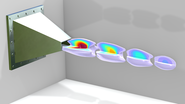
The Uncertainty Quantification Module reveals how variability of input parameters affects the simulation results.

“A strength of the Uncertainty Quantification Module is that it can be applied to any physical simulation covered by COMSOL Multiphysics,” says Jacob Yström, technology director of numerical analysis at COMSOL. “You are not limited to a certain field or application area, such as structural analysis, but can perform the same types of uncertainty analyses on applications based on acoustics, fluid flow, electromagnetics, and so on, and even when these phenomena are coupled. This makes this product wide-ranging and very powerful.”

COMSOL Multiphysics Version 6.0 improves performance and expands modeling capabilities
COMSOL Multiphysics version 6.0 includes important updates to the software platform and add-on products. This includes performance improvements through speedup and memory consumption by a factor of 10 for certain engineering applications. Feature enhancements include more efficient electromagnetic simulation of PCB designs and a new realm for acoustics modeling: flow-induced noise.

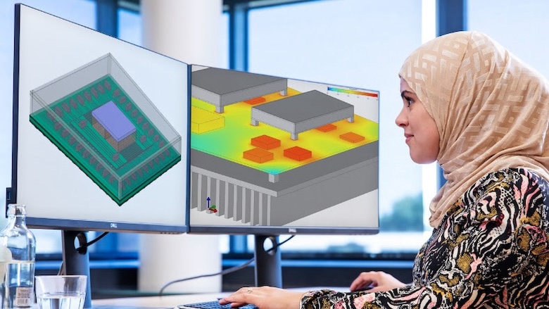
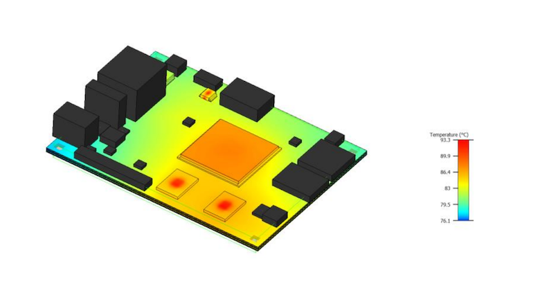
COMSOL version 6.0 delivers performance improvements and simplifies simulation of many important applications, such as printed circuit board (PCB) design (pictured).

Details about new features and improvements across the entire product suite are available in the COMSOL Multiphysics Version 6.0 Release Highlights.

COMSOL
www.comsol.com


Filed Under: COMSOL Tagged With: COMSOL

Using simulation to ensure multimode pacemakers synchronize communications

December 15, 2021 By Leslie Langnau Leave a Comment

By Dixita Patel

Recent advances for pacemaker technology include improved electronics and smaller batteries, making the development of leadless cardiac pacemakers (LCPs) possible. An LCP is a self-contained (capsule-like) generator and electrode system that eliminates the need for pocket or transvenous leads that often cause malfunctions. The current LCPs on the market pace at a single location of the heart, but for patients who require more than single-chamber stimulation, a multinode LCP system (Figure 1) can be used. Multinode LCP systems require synchronization between all of the implanted devices to function properly. However, the standard communication techniques used may be unsuitable due to constraints in terms of power consumption and size.

To help make the system and communication more efficient, researchers at MicroPort CRM are using simulation to investigate these design challenges using galvanic intrabody communication (IBC). IBC provides a power-optimized solution to facilitate communication between devices, which in turn helps to synchronize multinode LCP systems.

Multinode LCP system with two implanted capsules. The heart figure has been modified and reprinted by permission of Pearson Education, Inc., New York, New York.

Intrabody communication transceivers for LCP applications

Intrabody communication (IBC) is a near-field communication method that uses an electrode pair to send an impulse through body tissue to a second electrode pair that receives the signal. This method works with ultralow power, and no additional antennas are needed because the electrodes used for pacing also provide the electric field for the communication.

Mirko Maldari, an electronic engineer at MicroPort CRM, and his team proposed a new methodology to further characterize these types of communication channels. “With IBC, because electrodes are used to communicate [instead of coils and antennas], we can optimize both power consumption and size,” said Maldari.

In their research, an in vivo study was performed using a system that consisted of two capsules that were implanted in the right atrium and right ventricle of a heart shown in Figure 1. Further analyses involved the COMSOL Multiphysics software to measure the attenuation of the channel and estimate how much power is dissipated in the tissue.

Analyzing IBC pathloss with simulation

The team at MicroPort collaborated with Synopsys Inc., an electronic design automation company, using the Synopsys Simpleware software to develop a model of a human torso that would be importable into the COMSOL Multiphysics software (Figure 3). The model is based on a validated human phantom from IT’IS Foundation Zurich; more specifically, the “Duke” model, which represents a 34-year-old male.

LCP prototype for IBC channel studies.

The geometrical model was created to include organs, muscles, bones, soft tissue, and cartilage. After importing into COMSOL Multiphysics, an approximated version of the heart chambers was built to distinguish heart muscle from blood. Maldari said: “It was important for my application for these features to be included because they have different electrical properties.” The team then designed two identical LCP capsules in COMSOL Multiphysics to estimate the attenuation levels of the intracardiac channel.

Torso CAD model imported into COMSOL Multiphysics; cross-sectional view.

The capsules were studied at two different orientations, both at a channel distance of 9 cm. Simulations were performed with a quasistatic approach using the Electric Currents interface in the AC/DC Module, an add-on product to COMSOL Multiphysics, to calculate the channel attenuation in a frequency range between 40 KHz and 20 MHz. The results in Figure 4 show the positions of the right atrium (RA) capsule of the worst-case scenario (perpendicular) and the best-case scenario (parallel). The best-case scenario shows a higher differential voltage across the receiving dipole. The attenuation levels of both scenarios can be seen in Figure 5, where the difference is ~11 dB. From 40 kHz to 20 MHz, the attenuation decreases by ~5 dB for both cases. From the results, Maldari and his team were able to verify that relative position and orientation of the capsules strongly impacts the channel attenuation.

RA capsule positions for worst-case (left) and best-case (right) scenarios.


For MicroPort, it was important to estimate the attenuation levels before preparing the prototype. “As researchers and scientists, we try to reduce the amount of animal trials, and simulation has allowed that,” said Maldari. “It is a powerful tool to estimate the behavior of the signals within biological tissues before investigating them experimentally.” The use of simulation allowed the team to define accurate models for galvanic IBC communication and optimize transceivers for LCP systems.

Attenuation levels of the intracardiac channel for both scenarios.

Future plans for IBC

MicroPort’s future plans involve further studies, where the effect of certain input parameters — such as the electrode size and dipole lengths — on a more complete set of electric field parameters will be investigated. This would help them point out the attenuation difference between diastolic and systolic periods. As of now, the researchers are working on the design of an ultralow-power receiver for LCP synchronization purposes. The new receiver could potentially mark groundbreaking innovation for dual-chamber pacemakers.

COMSOL
www.comsol.com

Reference
Maldari, Mirko, et al. “Wide frequency characterization of Intra-Body Communication for Leadless Pacemakers”, IEEE Transactions on Biomedical Engineering, vol. 67, no. 11, pp. 3223–3233, 2020.

Synopsys and Simpleware are trademarks and/or registered trademarks of Synopsys, Inc. in the U.S. and/or other countries. COMSOL Multiphysics is a registered trademark of COMSOL AB.

Filed Under: COMSOL Tagged With: COMSOL

Designing out loud

December 15, 2021 By Leslie Langnau Leave a Comment

Voice and haptic feedback could ease CAD complexity speed design but is slow-to-market due to that very CAD complexity.

By Jean Thilmany, Senior Editor

“Computer, draw me a circle.”

You won’t be saying that to your computer-aided design system anytime soon. Even as Alexa and other speech-recognition systems have become ubiquitous over the past decade, voice-controlled CAD remains elusive.

Developers say design software that responds to verbal commands could cut the learning curve, make it easier to work with a system, and slash design time.

Perhaps it’s no surprise that voice-controlled CAD isn’t here. CAD is vastly more complex than the speech recognition tools we use today. Asking Alexa to turn up the thermostat or dictating a text message is very different than verbally controlling geometries, parts, and mechanical forces on a screen.

When will voice-controlled CAD be commonly available? It’s difficult to know.

Yet CAD systems that “hear” and follow commands could allow design teams to zoom in on the specifics of a CAD model and to make changes during a meeting. Designers could quickly add, remove, or update information in design databases and could quickly make routine requests, like opening a screen or drawing a circle. Down the line, they may be able to do away with keyboard and mouse and to design a model via voice command.

The concept of voice-controlled CAD is not new, but getting there is difficult.

In 2009, researchers at the University of Hong Kong proposed a method for voice-controlled CAD. A decade later, scientists at Purdue University and at two Spanish universities set out a method for using voice to capture design intent and annotation. Throughout the years, other systems have been proposed but they remain expensive to realize and implement.

Meanwhile, designers still rely on their keyboard and mouse.

Is voice practical?

An AutoCAD LT user echoed this frustration, asking in mid-2020 in the software’s community forum why voice-command wasn’t a feature on the CAD program.

While an AutoCAD image is depicted here, you can’t verbally ask any CAD system today to draw you a circle, much less to create and combine parts for the complicated assemblies used for heavy equipment. Credit: Autodesk

“Voice command could result in titanic time savings. Consider the chains of actions that could be bypassed by a single voice command,” the user wrote. “Just stating a sketch sometimes requires moving your cursor to change from the manufacturing environment to design.

Why not just double mouse click and say ‘concentric circle’ or whatever your first sketch move is to be?”

Answers varied, several suggesting the user learn keyboard shortcuts and write macros to speed drafting time. Some point out the time spent voicing the words “concentric circle” could quickly be spent hitting a key for a macro to make the circle.

Others suggested training already available commercial voice-recognition technology to open the macros.

“Voice commands regarding drafting are just not practical,” one community member responded. “The only way I see voice commands being used is ‘Alexa, make a PDF and send this drawing to Gavin with subject: project voice.’”

Moving beyond today’s speech recognition systems isn’t yet practical, but would be necessary for CAD’s complexity, says Natalie Hutchins, an engineer and writer at IndiaCAD, which provides outsourcing services.

While your Amazon Echo Dot may carry out your commands, don’t expect your CAD system to respond to sound of your voice. Credit: Wikicommons

Hutchins created a table that compared the features of the voice-recognition programs from Nuance, Microsoft, and Google. None of the three could interpret spoken words in the correct context with complete accuracy, she found.

Not too long ago—though a lifetime ago by technology standards, so about 30 years—the mouse and the graphical display were huge engineering design breakthroughs. CAD came along at the same time as computer graphics programs. Both technologies allowed shapes to be depicted on the computer screen that had been dominated until then by blinking letters and numbers.

For the first time, engineers could depict images in on-screen and make quick changes to the dimensions and shapes when needed.

CAD advancements have continued apace. Three-dimensional CAD became commonplace. Analysis software is now tied too CAD so engineers can immediately analyze their designs and make changes where needed.

Ironically, continued CAD updates keep the systems from being compatible with voice technology.

Today’s designers often browse among hundreds of CAD icons and menu scripts and switch between various command panels in order to do a modeling task, write the University of Hong Kong researchers. Ascribing voice commands to each or these actions is impossible and would make the designer’s life harder, not easier.

The researchers’ paper, “Natural Voice-Enabled CAD: Modeling Via Natural Discourse” appeared in the January 2009 edition of the journal Computer-Aided Design and Applications. Sukui Xue was lead author; the paper was his mechanical engineering postdoctoral thesis.

While voice-driven CAD commands would be of “tremendous benefit,” the technical challenge of creating and implementing the technology means it likely won’t be available in the near future, Hutchins says.

Speaking in CAD talk

That hasn’t held CAD companies back from trying.

The CADmaker think3 met with some success with a 2000 software update that included a speech-enabled graphical user interface, which allowed the user to issue commands without scrolling through icons and pull-down menu trees. This reduced the clutter of dialog boxes, saved time, and increased productivity, according to the company’s marketing materials of the time.

Voice input provides designers with a third option, along with the mouse and the keyboard, for entering commands or numerical inputs. The software was able to recognize several hundred voice commands, including basics like draw, zoom, redraw, fit view, and line. The software also recognized numerical values.

Because of technology’s inevitable march forward, engineers will one day be able to design via commands spoken aloud. Credit: Wikicommons

The feature used Microsoft’s Speech Application Programming Interface version 5.0, an interface for third-party application developers, according to think3.

But as it added functionality to the new release, think3 had to steer a careful path between complex CAD and ease-of-use, since the company cites simplicity as a major selling point, the University of Hong Kong researchers say.

The California CADmaker closed its doors in 2011, though the move had nothing to do with its system’s voice-recognition capabilities.

In 2005, Enact Technologies introduced Speak4CAD, compatible with AutoCAD software. During beta-testing, the software doubled CAD productivity, as measured by comparing manual drawings to those created by spoken drawing commands and dimensions, said Bruce Swan at the time. He was Enact Technology senior partner at the time.

The technology was specifically written for AutoCAD commands to make it faster than standard speech-recognition software that must search for terms, Enact wrote in its marketing materials at the time. The user would dictate commands and numbers as they move the mouse, to eliminate the use of the keyboard.

Enact Technologies is no longer around. It’s not clear whether the business folded or was purchased by another company.

The think3 and Speak4CAD systems relied on predefined, targeted words and phrases, which allowed users to use relatively complicated expressions such as “view from left” and “add a circle,” Xue writes.
“However, this method still restricts the user’s expressive style by all of pre-defined rules,” he and his teammates write in the paper. Users must also remember all the fixed words and expressions.

“This impedes the freedom that might have been brought by speech, because too many restrictions have been added to the users’ expressions,” the researchers say.

They put forward a verb-based semantic search approach that would extract useful information from voice-issued sentence commands. Users would say: “draw me a circle that has a radius of 2.5 inches.” Rather than “circle; radius; 2.5 inches.”

“Natural voice-enabled CAD frees CAD users from the buttons and menu by allowing natural discourse as the input. Natural discourse is also less restricted than the previous voice-based systems,” the researchers state in their paper.

Despite these merits, their system has limitations, they acknowledge. Because it doesn’t eliminate the mouse, those with paralysis or other types of disabilities can’t use it. Also, it should recognize more natural phrasing and should be able to be used without training, the researchers say.

Their proposed system isn’t yet included within commercially available CAD software.

Annotation while speaking

In the face of technical limitations of using voice for design, some researchers are looking at voice-driven 3-D annotation to aid collaborative design, as voice-annotation may be easier to develop and implement than voice-driven design.

Annotation enables the exchange of design intent and rationale with other users directly through the 3-D model, says a research team of mechanical and construction engineering professors from Purdue University in Lafayette, In., and from Jaume I University and the Valencia Polytechnic University in Spain.

Their paper, “A voice-based annotation system for computer-aided design” appeared in the April 2021 edition of the Journal of Computational Design and Engineering.

Much of the information generated during the product design process is unstructured, writes Raquel Plumed, lead author and mechanical engineering professor at Jaume I University. That is, much of the design information is exchanged verbally and isn’t captured within the CAD system.

This information takes the form of facts, suggestions, informal conversations, discussions, and opinions.

Such information—communicated during informal conversations or even formal meetings—can be critically important for data integration, collaboration, process efficiency, productivity, and error reduction, she and her colleagues write.

“But the knowledge is often not captured or archived for future use because the process is time consuming, inefficient, and not cost efficient,” they say.

The researchers give the example of design rationale, which aims to capture information about the reasoning, motivation, and justification for design decisions and to describe their relation to other decisions.

Much of this might take place during a quiet conversation between two engineers. But it’s time-consuming to write down and store verbal conversations and then to find them again.

“Furthermore, engineers and designers often used vague expressions in their verbalizations of a problem or a design approach, particularly during the early stages of the design process, which makes it difficult to establish semantics in CAD models,” they say.

They put forward a voice-based software to annotate 3-D models directly within CAD software.
Their method automatically captures audio signals and transcribes them to a 3-D note, which is attached to the geometry in the right spot and is available to other product information and business processes across the enterprise, such as a product management system.

These researchers join others in describing how CAD systems could best incorporate voice commands. Still, voice-activated CAD remains out of reach, likely due to cost and complexity.

Or, as one user put it in the AutoCAD LT forum: “Unless commercial CAD systems adopt voice technology, we won’t be seeing it anytime soon.”

AutoDesk
www.autodesk.com

Filed Under: Autodesk Tagged With: Autodesk

Hexagon showcases advanced CAD/CAM software at WESTEC 2021

November 16, 2021 By WTWH Editor Leave a Comment

Hexagon’s Manufacturing Intelligence division announced it is exhibiting the newest releases of EDGECAM and WORKNC at WESTEC 2021, Long Beach Convention Center, Long Beach, CA, from November 16 -18, 2021. In Hexagon Booth #945, attendees will find CAD/CAM software technologies offering future-ready features for trending advancements in manufacturing. EDGECAM 2022’s newly-added support for 6-axis milling and turning machines enables programming of the cutter head into positions previously out of reach in just one set-up, which in the past required a series of sequences. The software also supports 3+2 machining and complex 5-axis simultaneous milling in all configurations. Also integrated with EDGECAM is a new component called NCSIMUL Essential providing full simulation of 3-axis milling parts. NCSIMUL is Hexagon’s high-end CNC simulation software for G-code verification. Users can dynamically interact with a toolpath and pinpoint exactly which line of code is being simulated. WESTEC visitors can see these late-breaking EDGECAM features and more demonstrated at regular intervals during the show.

Hexagon will also highlight the latest version of WORKNC computer-aided manufacturing (CAM) software designed for mold and die makers. The software’s newest enhancement is the integration of a ‘manufacturing aware’ computer-aided design (CAD) application called DESIGNER. All WORKNC users now have on-demand access to CAD functionality to heal missing faces, extend surfaces, and cap holes and pockets in preparation for manufacturing. Users can also employ a hybrid design approach combining surface and solid entities using direct modeling techniques. A one-click transfer of completed designs directly into the CAM software makes the entire process even faster for efficient production. Also notable are the new advances in WORKNC’s programming capabilities that reduce the time spent calculating toolpaths and help to generate faster, more efficient code for reduced cycle times.

During WESTEC, Hexagon will also feature several other technologies including the new-to-market reverse engineering software REcreate which enables users to move from a point cloud to mesh to solid in order to create manufacturing-ready formats. For visitors interested in metrology solutions, the new generation Inspire inspection software will be shown interfacing with Absolute Arms, a Leica Absolute Tracker, and the latest in ultra high-speed laser scanners – the Absolute Scanner AS1. The TEMPO part loading system will be demonstrated with a TIGO coordinate measuring machine (CMM), which facilitates innovative autonomous measurement and lights out quality control. The latest m&h probing systems for machine tool measurement will also make their debut at WESTEC.

Hexagon
hexagonMI.com

Filed Under: Hexagon software Tagged With: hexagonsoftware

3D CAD & CAE manufacturer catalogs powered by CADENAS now available in SOLIDWORKS Electrical 3D

October 29, 2021 By WTWH Editor Leave a Comment

Good news for all electrical engineers and component manufacturers: SOLIDWORKS Electrical 3D joins the long list of software solutions for CAD, CAE, PLM and simulation that offer direct access to thousands of digital manufacturer catalogs powered by CADENAS. Millions of manufacturer-verified 3D CAD and CAE data are now directly integrated into the popular solution for electromechanical design. By integrating the Strategic Parts Management PARTsolutions, users have access to not only the countless 3D CAD models. They also benefit from an extensive selection of standards as well as intelligent functions for managing and finding proprietary, purchased and standard parts.

Optimized cooperation between MCAD and ECAD divisions
The electrical design situation is different from mechanical design, where not only, but above all, the geometries of the digital components are decisive. Electrical engineers need information about circuit diagram symbols, connections, component types (connector, cable, standard component, terminal, etc.) or parent-child relationships when selecting the appropriate component. The product models must also provide information on which connectors are compatible or how the installed components are to be correctly dimensioned in relation to each other. If this data is not stored within the CAD model, it must be compiled in a time-consuming process from various sources. Multi CAD capable product data based on CADENAS technology enables seamless collaboration between ECAD and MCAD, as component information can easily be transferred between mechanical and electrical design – without loss of information.

SOLIDWORKS Electrical 3D by Dassault Systèmes provides additional support for smooth electromechanical collaboration. With the software module, design data of circuit diagrams can be integrated bidirectionally into the 3D model of a machine or assembly. ECAD components such as wires, cables and harnesses can be easily positioned and automatically routed in the 3D MCAD model. Design and bill of materials are also synchronized in real time, minimizing sources of error.

The software indicates which connectors are compatible or how the installed components are to be correctly dimensioned in relation to each other. If this data is not stored within the CAD model, it must be compiled in a time-consuming process from various sources. Multi CAD capable product data based on CADENAS technology enables seamless collaboration between ECAD and MCAD, as component information can easily be transferred between mechanical and electrical design – without loss of information.

Dassault Systèmes
www.3ds.com

Filed Under: Dassault Systemes, SolidWorks Tagged With: dassaultsystemes

Autodesk Fusion 360 App Version 2.0 gives instant manufacturability feedback

October 20, 2021 By Leslie Langnau Leave a Comment

Xometry, Inc., a leading AI-enabled marketplace for on-demand manufacturing, announced the launch of version 2.0 of its app for Autodesk Fusion 360. The app is free and can be downloaded directly from the Autodesk Fusion 360 App Store.

Updated with new features in addition to the instant price and lead time capabilities launched earlier in 2021, Version 2.0 now offers manufacturability feedback and multiple part upload features, improving processes for engineers and designers working in Autodesk. With manufacturability feedback, engineers and designers receive information on part manufacturability while they are designing in the Fusion 360 interface, allowing them to improve their designs. And with the ability to upload multiple parts, engineers can price and receive feedback on multiple parts at the same time, streamlining their work. Version 2.0 is a critical enabler for engineers looking to fast-track product iterations and incorporate real-time feedback.

Xometry offers an exclusive 10% discount on all custom parts orders placed through Autodesk Fusion 360 app in the US. The company is also rolling a European version of the app with multiple languages and pricing in Euros.

Xometry also offers an add-in for Autodesk Inventor. The Inventor add-in is available for free on Xometry’s website along with other popular CAD software add-ins.

Filed Under: Autodesk Tagged With: Autodesk, xometry

  • Go to page 1
  • Go to page 2
  • Go to page 3
  • Interim pages omitted …
  • Go to page 79
  • Go to Next Page »

Primary Sidebar

3D CAD NEWSLETTERS

MakePartsFast

Follow us on Twitter

Tweets by 3DCADWorld

Footer

3D CAD World logo

DESIGN WORLD NETWORK

Design World Online
The Robot Report
Coupling Tips
Motion Control Tips
Linear Motion Tips
Bearing Tips

3D CAD WORLD

  • Subscribe to our newsletter
  • Advertise with us
  • Contact us
Follow us on Twitter Add us on Facebook Add us on LinkedIn Add us on Instagram Add us on YouTube

3D CAD World - Copyright © 2022 · WTWH Media LLC and its licensors. All rights reserved.
The material on this site may not be reproduced, distributed, transmitted, cached or otherwise used, except with the prior written permission of WTWH Media.

Privacy Policy