SolidWorks 2024 is officially released to help engineers reimagine design. The What’s New in SolidWorks 2024 website is live and packed with information to get you up to speed on the latest enhancements.
The new version enables design engineers to:
- Collaborate with other users, even if they are using an older SolidWorks version.
- Employ new assembly modeling workflows to speed up large assembly design, documentation, and collaboration.
- Speed up sketching and more easily capture and communicate design intent while reducing design effort.
- Create drawings that communicate designs more clearly with standardized chain dimensions layout, efficient dimension reattachment, and reduced DXF export post-processing.
- Reduce sheet metal manufacturing bottlenecks by adhering to sheet metal manufacturing standards.
- Build and modify complex structures more easily.
- Handle more complex electrical routing scenarios with new options for flattening, reorienting, and displaying wires and connectors.
- Create more informative electrical documentation faster while reducing errors.
- Communicate designs more clearly in 3D with the ability to display dual dimensions and export Hole Tables and custom properties.
- Experience easier optimization and more advanced real-life rendering capabilities.
Learn about the top 10 new capabilities of SolidWorks 3D CAD 2024 and watch the launch video for software demonstrations:
SolidWorks
solidworks.com
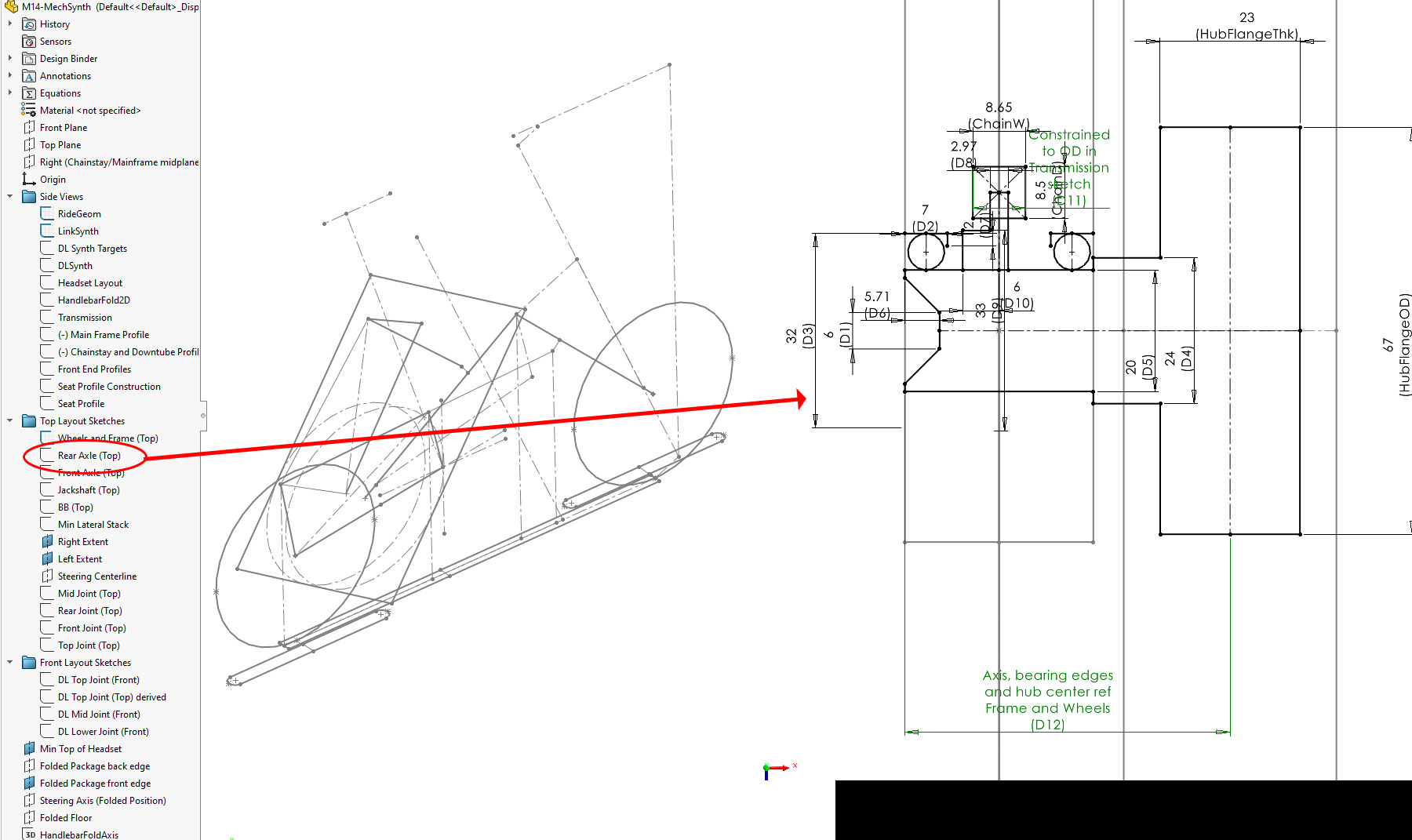
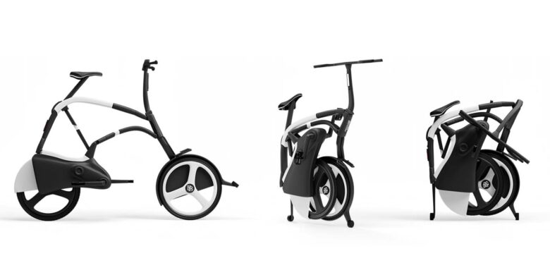
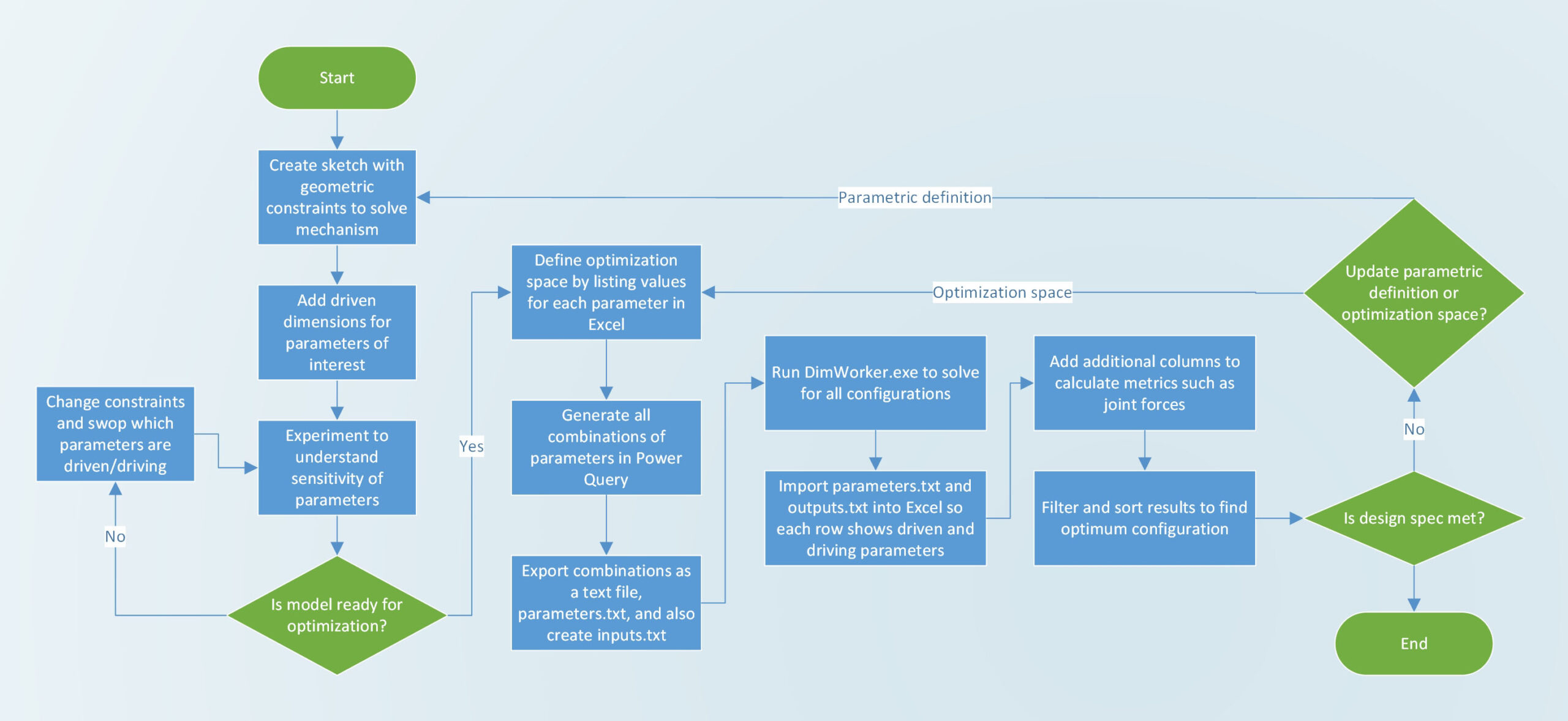
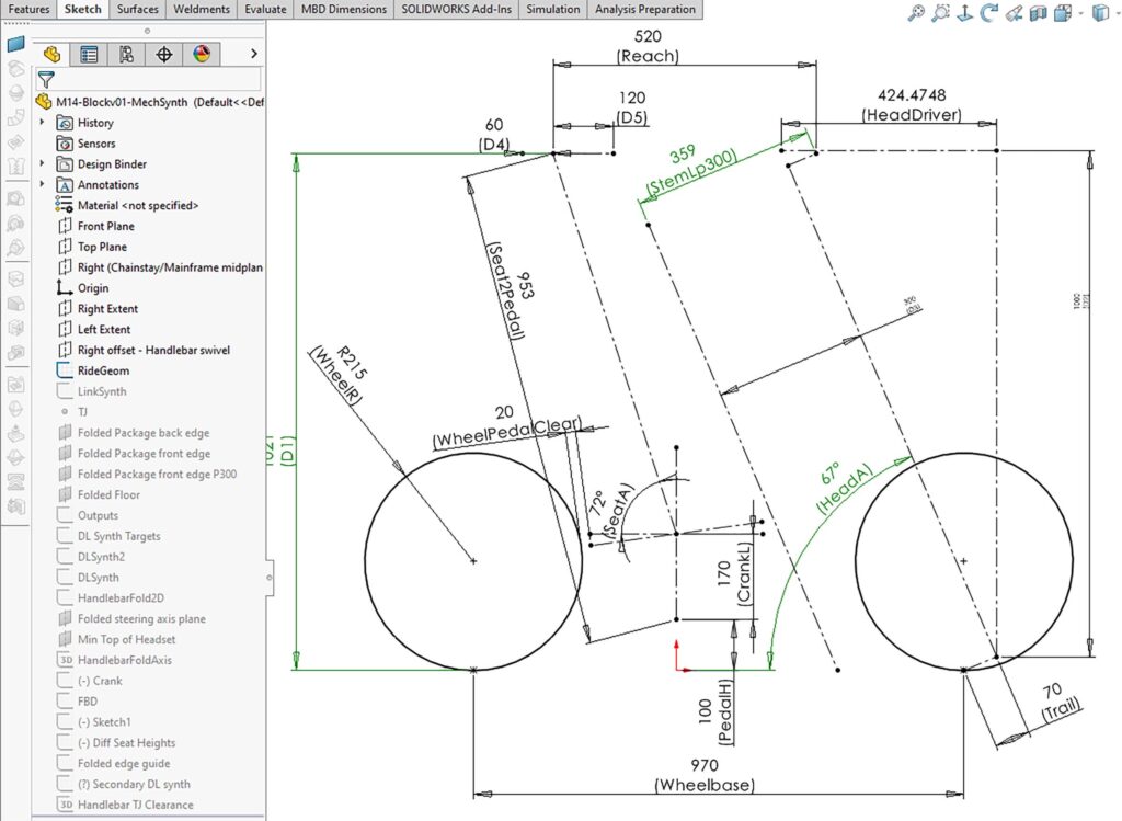
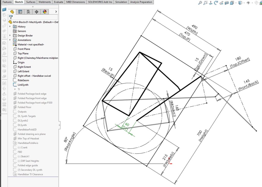
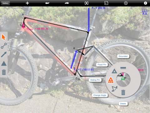
 A demonstrator had already been created, which proved the bike could be unfolded in less than half a second. However, it was still a bit too wide when folded, and optimizing the mechanism to further reduce the folded width without impacting the important ride characteristics was proving challenging. The large number of constraints that needed to be simultaneously satisfied meant that a direct solution to find the optimum mechanism was not possible. This method of using a script to generate multiple solutions was therefore created.