One of the CAD giants, Dassault Systemes, announces the latest release of its 3DEXPERIENCE platform’s on-premise and on-the-cloud portfolio of solutions. Release 2014x of the 3DEXPERIENCE platform, available to all customers on February 24, includes an on-premise portfolio of 41 industry solutions and their 183 processes, plus a dedicated cloud portfolio of 14 industry solutions, with more than 60 processes, appropriate for businesses of any size.
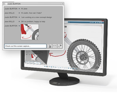
Included in this release is SolidWorks Mechanical Conceptual, which was announced at this year’s SolidWorks World event. Reception for this new product among beta users has been positive, particularly for its collaboration features and social network-like interface.
“With SolidWorks Mechanical Conceptual, we were able to do four process revisions by the time our competitors were only doing their secondary revision,” says William MacLeod, senior engineer, Kennedy Hygiene. “The key reason for that is the collaborative aspect of Mechanical Conceptual, which permitted our customers to log in, see real time updates of the process and share ideas with us through the blog.”
On-premise portfolio covers gamut of product development tasks
The 3DEXPERIENCE® Process Portfolio On Premise expands capabilities already available on the V6 portfolio and unifies the user experience for all processes and industries. Built to answer customer- and industry-specific needs for ease of use and lower training costs, the open architecture allows customization and the integration of customer data into a single environment. It provides a single source for truth by integrating all data required to create a process experience while eliminating costly IT operations, such as database replication.
A single, compass-like interface provides easy-to-use navigation, search, and collaboration in the 3DEXPERIENCE platform environment that is extensible to any discipline in the company – engineering, manufacturing, simulation, sales, marketing, finance, procurement, and management.
Cloud offerings offer users lower cost of ownership
The 3DEXPERIENCE® Process Portfolio On Cloud expands capabilities already available on the V6 portfolio and unifies the user experience for all Processes and Industries. Offered as Software-as-a-Service (SaaS) on public cloud to provide increased flexibility and fast deployment, it includes services and support of the cloud provider in the price of the Processes, with Dassault Systèmes as the single point of contact.
The public cloud operates 24 hours per day, 7 days per week, 365 days per year, and includes maintenance, licensing and upgrades. Total Cost of Ownership is improved by reducing requirements for computing and storage, as well as facility and human resources costs, since hardware is no longer required.
A single, compass-like interface provides easy-to-use navigation, search, and collaboration in the 3DEXPERIENCE platform environment that is extensible to any discipline in the company. The on cloud process portfolio also includes the following out-of-the-box capabilities:
* 3DDashboard brings information from diverse sources into one fully customizable web page
* 3DSwym enables cross-discipline collaboration of communities of users from anywhere in the enterprise
* 3DPassport provides a single sign-on for every 3DEXPERIENCE application licensed by the user
A complete list of Release 2014x offers and operating conditions is available here.
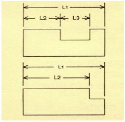
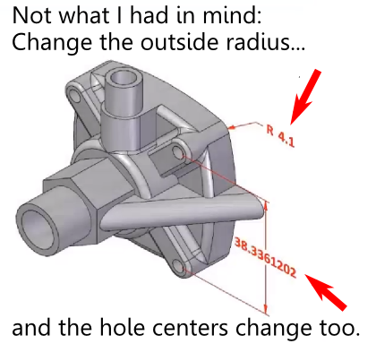 What is the failed promise of parametric CAD? In short, model reuse.
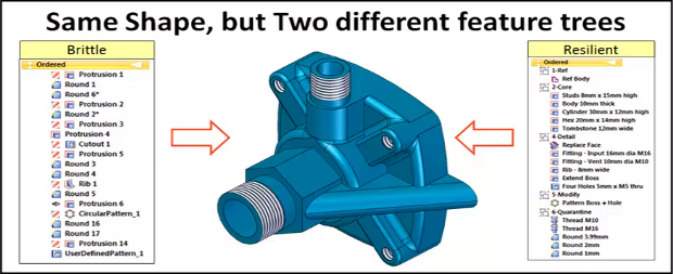
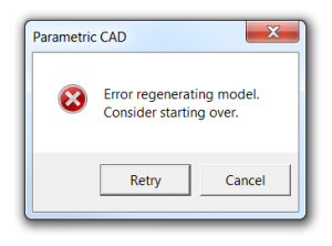
 The model brittleness problem inherent with parametric feature-based modeling is a really big deal. And it’s something, honestly, that I don’t have a great answer for. I’ve even asked a few power users who I know, and their answers seemed to involve a bit of hand-waving, and a reference to having lots of experience.
 Direct modeling—a syncretic melding of concepts pioneered by CoCreate, Trispectives, Kubotek (and many others)–has shown the most promise to cure the parametric curse.
 A few days ago, SolidWorks CEO Bertrand Sicot