• Skip to primary navigation
  • Skip to main content
  • Skip to primary sidebar
  • Skip to footer

3D CAD World

Over 50,000 3D CAD Tips & Tutorials. 3D CAD News by applications and CAD industry news.

  • 3D CAD Package Tips
    • Alibre
    • Autodesk
    • Catia
    • Creo
    • Inventor
    • Onshape
    • Pro/Engineer
    • Siemens PLM
    • SolidWorks
    • SpaceClaim
  • CAD Hardware
  • CAD Industry News
    • Company News
      • Autodesk News
      • Catia News & Events
      • PTC News
      • Siemens PLM & Events
      • SolidWorks News & Events
      • SpaceClaim News
    • Rapid Prototyping
    • Simulation Software
  • Prototype Parts
  • User Forums
    • MCAD Central
    • 3D CAD Forums
    • Engineering Exchange
  • CAD Resources
    • 3D CAD Models
  • Videos

Catia

The failed promise of parametric CAD, final chapter: A viable solution

November 18, 2013 By Evan Yares 5 Comments

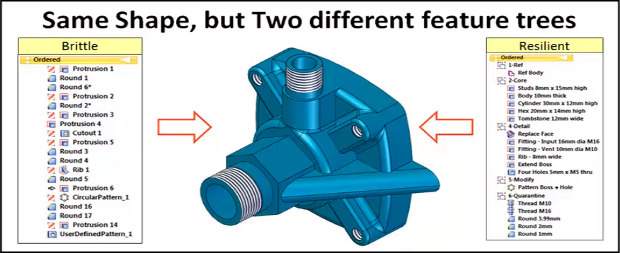
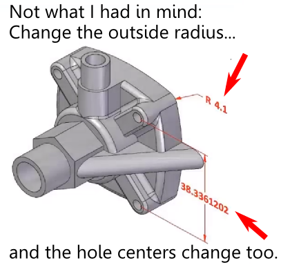
Model reuseWhat is the failed promise of parametric CAD? In short, model reuse.

It’s a lot more difficult than it ought to be, for a variety of reasons. Several months back, I wrote a series of articles discussing those reasons, as well as some of the solutions that have come up over the years.  What was missing from the series was a final chapter; a detailed description of what could prove to be a viable solution to problems with model reuse: the resilient modeling strategy.

The resilient modeling strategy (RMS) is the brainchild of Richard “Dick” Gebhard. I wrote about Dick last June, in the article A Resilient Modeling Strategy. He’s a low-key guy with deep experience and serious expertise in the practical use of MCAD software. Over his career in CAD, he’s been a reseller for CADKEY, Pro/E, and most recently, Solid Edge.

RMS is a best practice for creating CAD models that are stable and easily reusable (even by inexperienced users.)  It can be learned and easily used by typical CAD users, it preserves design intent in models, and provides a mechanism by which managers or checkers can quickly validate a model’s quality.

Resilient Modeling Strategy

When Dick first started thinking about the concepts that make up the resilient modeling strategy, it was natural that it was in the context of showing the advantages of Synchronous Technology (The Siemens PLM brand name for its version of direct modeling.) In our discussions about RMS over the last year or so, I pointed out that, while I thought that RMS did indeed demonstrate the benefits of hybrid history/direct modeling in Solid Edge, for it to be taken seriously, and not be unfairly dismissed as a marketing initiative for Solid Edge, it needed to work with a wide variety of MCAD tools. I think Dick got where I was coming from, because he’s continued to refine and generalize RMS, with feedback from users of a number of MCAD systems.

In its current incarnation, RMS works particularly well with Solid Edge, as might be expected, but also works very well with Creo, NX, CATIA, and IronCAD (all of which are hybrid history/direct systems.) Further, with a few modifications, it can provide compelling value with SolidWorks, Inventor, and Pro/E (all of which are primarily history-oriented systems.)

It’s significant that RMS is also free to use. While Dick is available to provide presentations, seminars, and training, he has not attempted to patent, or keep as trade secrets, the underlying concepts of RMS. (He does claim a trademark on the term “Resilient Modeling Strategy,” which means that organizations offering commercial training on RMS will need to get Dick’s OK to use the term.)

Dick has posted an introductory presentation on RMS at resilientmodeling.com. While the entire presentation is 20 minutes long, the first 3-1/2 minutes cover the problems that people invariably experience when reusing or editing history-based CAD models. Watching that much will likely convince you to watch the rest.

On Wednesday, November 20, at 10:00 AM PST, Dick will be hosting a webinar on RMS. It’s scheduled to last just 30 minutes, with the emphasis on content, not hype. If you’re a serious CAD user or a CAD manager (or, for that matter, you work for an MCAD developer), it’ll be well worth your time to attend.

TL;DR: Resilient Modeling Strategy is a best practice for creating high quality reusable 3D MCAD models. It works with many CAD systems, it’s easy to learn and use, and it’s free. Big payoff for MCAD users. 

Presentation at resilientmodeling.com

Register for Nov 20 webinar on Resilient Modeling


Filed Under: Catia, Creo, Evan Yares, Featured, Inventor, News, Pro/Engineer, Siemens PLM, SolidWorks Tagged With: 3D CAD, Catia, Dassault Systemes, Evan Yares, Inventor, IronCAD, PTC, Siemens PLM, Solid Edge, SolidWorks

3D Master

May 28, 2013 By Evan Yares 3 Comments

3D MCAD is not “done.”  Not by any means.

Well over 40 years after the introduction of commercial 3D MCAD products, and 25 years after the introduction of feature-based solid modeling MCAD, many MCAD programs aren’t totally 3D. They’re 2D/3D.

What I mean by this is that their 3D capabilities are inadequate to represent real world products fully in 3D.  They have to rely on 2D drawings as a crutch, because their 3D annotation tools (GD&T and PMI) are either weak, or missing entirely.

In short, with many CAD systems, 2D is the master. Not 3D.

Recently, Dassault Systemes posted an excellent video showing the benefits of using a 3D master approach. I think it provides a good starting point for the discussion.

Filed Under: Catia, Evan Yares, News Tagged With: Catia

Hitting the reset button: Building the next generation of SolidWorks

July 10, 2012 By Evan Yares 14 Comments

Suppose you were a CAD developer, and you wanted to build a next-generation CAD system. How would you do it?
I’ve thought about that question for quite a while. Nearly 30 years, in fact. I’ve watched a bunch of attempts at building next-generation CAD systems. I’ve been involved in a few too. I can tell you this much: It’s not as easy as you think it is.

The folks at Dassault Systemes have also been thinking about it for quite a while. A few years ago, they previewed a new generation version of SolidWorks, called SolidWorks V6. They showed it in public one time, then shut up. And speculation about it has been rampant since.

Although I’m not a fan of the confusion that the name brings (See SolidWorks V6 is not SolidWorks), it’s possible that I might be a fan of the actual product, when it comes out.

Might. Because I’ve only seen one glimpse of it, and don’t know its details.

What DS has told us

Here’s what DS has been willing to say (or show), so far:

  • SolidWorks V6 is built on CATIA/ENOVIA V6 technology.
  • SoldWorks V6 uses the DS CGM (Convergence Geometric Modeler) kernel.
  • SolidWorks V6 can be delivered as a cloud application
  • SolidWorks V6 can run on Windows, OSX, or Linux
  • The team that is creating SolidWorks V6 is being headed up by Gian Paolo Bassi

These slim facts, though, are enough to provide some useful clues to with which to speculate on the nature of SolidWorks V6.

A few guesses on architecture

Let’s start with the CATIA/ENOVIA V6 technology: DS spent about $2 Billion to rebuild their V6 technology on a service oriented architecture (SOA.) You can read all about SOA on Wikipedia, but suffice it to say that it’s a good way of modularizing a CAD system, so you can deliver scalable capabilities and scalable performance.

With SOA, the back-end of the CAD system is delivered as a set of loosely coupled interoperable services, which can be run on a remote server or cluster, on a private or public cloud, or even locally, on your own computer.

One of the nice benefits of SOA is that, if implemented properly, and run in a virtual machine, the back-end services can run on top of nearly any operating system or hardware.

The front-end user interface (or client) for SolidWorks V6 could be built in any number of ways. DS has some impressive technology in its 3DVIA Studio (formerly Virtools) product. The 3DVIA Player, which is a browser plug-in, seems to be capable enough to be a CAD client. Yet, there are clues that DS may not be going this way.

The first clue is the inconsistency of platform support with 3DVIA Player. For example, there’s no 3DVIA player for Linux. And, while 3DVIA Mobile HD (which only supports static models) is available for the iPad, it’s not available for Android. And there is no 3DVIA Composer mobile player yet – despite DS having talked about publically two years ago. Take all this together, and it’s not hard to infer that it’d be difficult for DS to build a multi-platform CAD client using 3DVIA.

The second clue is that fat clients, such as 3DVIA Player, have fallen out of favor in recent years. Consider that Adobe has divested Flex and deprecated Flash. Microsoft has moved from Silverlight to Metro. Even Apple, long known for its proprietary proclivities, has become an HTML5 advocate.

A more modern approach to building a CAD client might be to use HTML5 and WebGL, in a compatible browser. You can see an example of this type of client in Tinkercad (or Sunglass.) While not nearly a competitor for SolidWorks (as a professional tool), Tinkercad does a nice job of demonstrating the feasibility of a browser-based CAD interface.

The important thing here is that the client front-end and services back-end in an SOA CAD system are logically separate, and can communicate using standard web services protocols. If a computer, tablet, or phone has the capability to run a sufficiently good browser, it can be used as a front-end for such a CAD system. If it has enough memory and computing power, it can be used to run the back-end. If it has both, it can run the entire CAD system. At that point, a modern SOA CAD system would be pretty much indistinguishable from a traditional desktop CAD system.

This, incidentally, is one of the slickest ways to get platform independence in a modern desktop application: Implement the front end in a browser, the back-end as services running in a virtual machine on the same computer, and use web services to connect the two. Using this technique, DS could theoretically deliver SolidWorks as a cloud-based SaaS (software as a service) app, as an enterprise network app (with a federated database), or as a standalone desktop app. All using the same code.

The modeling kernel

It’s no surprise that DS is planning to use CGM instead of Parasolid in SolidWorks V6. If they wanted to, they could actually use both, for backwards compatibility with SolidWorks V1 (that’s what they call the current version), though at an additional cost in licensing fees. (IronCAD, for example, uses both ACIS and Parasolid. And, though they don’t talk about it in public, DS almost certainly had internal test versions of SolidWorks running both ACIS and Parasolid many years ago. They would have been nuts not to, if only to cover their downside risk were their relationship with Siemens/Unigraphics to have soured.)

The real question with CGM is whether it will be compatible enough to Parasolid to provide 100% (not 99%) downward compatibility with SolidWorks V1. No one outside of DS’s development labs really knows the answer to that question.

Compatibility will come at one of two levels: Boundary representation (Brep), or feature-level.

CGM does support foundation-based tolerant modeling, so it should, in theory, be able to read Parasolid Breps accurately. But it’s not that simple.

Paul Stallings, VP of R&D for Kubotek pointed out the problem for me last year: “The most difficult problem with tolerances is not that one system uses one tolerance and another system uses another tolerance. The biggest problem is that some systems depend on curves in three dimensional space, and other systems depend on curves in the different two dimensional parameter space of the surfaces that they are on. The mis-match between parameter space and three dimensional space is a very big problem with ACIS and Parasolid using three dimensional space and Catia and ProE using parameter space.”

There are other problems on top of this. Parasolid and CGM likely define topology and geometry in different ways. Even seemingly simple shapes such as cylinders and spheres can be represented and parameterized differently. (I understand that CATIA represents cylinders as two half-cylinders.) Advanced procedural surfaces can involve many undocumented, cryptic, or even unimplemented options. When these surfaces are near-tangent to neighboring NURBS surfaces, fitting can be very difficult. And then there are problems with multiple flipping flags, for faces, edges, and curves. If you get one of them wrong, all is lost.

Still, DS has had some of their best people working on CGM for a long time. Their Spatial division has a really good understanding of Parasolid (they support it in their 3D InterOp data exchange products.) So, I give DS the benefit of the doubt, that they can work through any CGM/Parasolid Brep interoperability problems. At least to the 99% level. For the last 1%, technologies exist, such as Capvidia’s CompareWorks, which 100% validate translated model integrity.

Feature-level interoperability between SolidWorks V6 and SolidWorks V1 may be a shakier proposition. It depends on whether, given a feature’s recipe as an input, CGM is capable of generating the same exact same result as Parasolid.

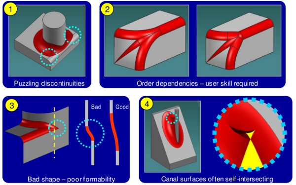
Consider blending (or filleting.) Blending functions in CAD systems, no matter what kernel they’re based on, are often unpredictable, counter-intuitive, and prone to failure. No vendor—not Siemens, not DS, not PTC, and not Autodesk—has “solved” blending. Here are a few examples of Parasold blending problems:

Parasolid blends

CGM will have its own blending problems, but it’s unlikely that they’ll be the exact same ones that Parasolid has. SolidWorks users are a hardy bunch, and have spent the last 17 years or so finding ways to work around strange blending behavior. So, even if CGM is actually technically better at blending than Parasolid, it could create problems when users are actually relying on getting identical results.

The important question may be: does it really matter?

If SolidWorks V6 doesn’t have feature-level compatibility with SoldWorks V1, it’ll be in good company. No other CAD system does either. Unless the two products are used in an iterative workflow, it’s likely that Brep level compatibility will suffice. And, while SolidWorks V1 doesn’t have advanced direct modeling tools for editing dumb Breps, that’s no reason to assume that SolidWorks V6 won’t. In fact, DS does have interesting direct modeling technology in CATIA V6. It would make sense that it might show up in SolidWorks V6. If that happens, SolidWorks V6 users may be able to import and reparamaterize SolidWorks V1 models. That opens up interesting possibilities.

Not just another CAD new system

So far, everything I’ve been talking about with respect to SolidWorks V6 is speculation, based on the small amount of information that DS has let out about the product. And this last bit is speculation too.

Gian Paolo Bassi, who is in charge of developing SolidWorks V6, is not a stranger to people in the CAD industry. If you check his patents, you’ll find that he’s one of the inventors of functional modeling. While I’m not going to explain functional modeling here, I will say that it’s a step beyond traditional feature-based modeling.

My guess is that DS wouldn’t have put Gian Paolo in charge of the SolidWorks V6 team if they were planning a me-too product.

In total, I’m guessing that SolidWorks V6 is going to be a really interesting product, but, at the same time, it’s going to be a very different product from SolidWorks V1. Giving up one for the other probably won’t make sense for quite a while.

User concerns

Over the last couple of years, I’ve watched a number of forums and  blogs, where users—often smart and experienced users—have expressed serious concerns about SolidWorks V6.

The concerns seem to come in several areas: compatibility with SolidWorks V1, cloud hosting (particularly of data), and SaaS licensing.

The compatibility issue is a technical issue driven by a business need. The choice of CGM over Parasolid is a strategic decision for DS. It doesn’t make business sense for DS to build a next major generation product on a competitor’s core technology. It’s true that this choice is going to impact users. The question that can’t be answered is how effectively DS will be able to minimize the impact.

But the other issues—cloud hosting and SaaS licensing—aren’t even technical issues. They’re business issues driven by technical capabilities. If Gian Paolo Bassi and his team build the V6 product right, it will open up the option of cloud hosting and SaaS licensing. It won’t close down the possibility of the software running on the desktop, with standard perpetual licensing.

Over the last few years, I’ve seen a lot of concern about the performance, reliability and security of cloud hosting, with respect to SolidWorks V6. They’re legitimate concerns—but they’re not inherent to SolidWorks V6. Consider this example: You can run the MySQL database or Apache web server on a cloud. Or you can run them right on your own computer. It’s your choice. You never see anyone fretting about their reliability, because experienced people recognize that the programs themselves are rock solid, and it’s the choice of hosting environment that can create issues.

The issues of performance, reliability, and security are key for SolidWorks V6. But, guess what? The core technology underlying SolidWorks V6 is already proven in CATIA V6. DS spent a couple of billion dollars to make sure it was up to the task. Now the question becomes one of hosting environment. That’s not a technical issue. It’s a business issue.

Business issues

I certainly have technical concerns about SolidWorks V6. But my biggest concerns have to do with business issues. Even if they get the product right, business decisions DS makes about deployment and licensing could create big problems.

To understand why this is an issue, you have to look at the shift in how DS has managed SolidWorks (the company) over time. Up until about 5 years ago, they pretty much left SolidWorks alone. Many SolidWorks users didn’t even know that the company was owned by DS. But, starting in about 2007, that began to change. Today, SolidWorks is very much a part of DS. While many of the same people are there, it’s become clear that the company’s strategy is driven by the DS executive committee, in France.

In the past, SolidWorks management was exceptionally open and transparent in their communications (at least, compared to most other big CAD companies.) Over time, SolidWorks management earned their users’ trust.

DS management, however, has a reputation for being notoriously tight-lipped when it comes to talking about anything they perceive might weaken their competitive advantage. It seems to be cultural, possibly born out of competing for the largest aerospace and automotive accounts.

To the extent that DS retains that tight-lipped tendency when engaging with SolidWorks users, it may not serve them well.  DS top management, particularly the people driving strategy, haven’t paid their dues, and earned SolidWorks users’ trust.

There are a million plus existing SolidWorks users, and many of them seem to be imagining the worst possible scenarios about SolidWorks V6.

While in many cases, FUD (fear, uncertainty, and doubt) are sewn by competitors, in this case, the FUD comes, in part, from DS’s reticence to reassure users that SolidWorks V6 is going to be a good thing (and not a tool to lock them in and bleed them dry), and, in part, from users’ legitimate concern that DS might be losing interest in SolidWorks V1.

SolidWorks 2013

It’s possible that the best answer for the concerns of existing SolidWorks customers will be in SolidWorks 2013. To the extent that the new release improves stability, and adds significant value over the previous version, users may be willing to relax their concerns that DS might be losing interest in the existing SolidWorks product line.

While the 2013 product is now in beta, SolidWorks will be officially launching it in September. I understand that they’ll be sharing their product roadmap at that time. This may be SolidWorks CEO Bertrand Sicot’s best chance to quiet the concerns, and build anticipation about SolidWorks V6—a product that could ultimately turn out to be a truly great next-gen CAD system.

Filed Under: Evan Yares, Featured, News, SolidWorks Tagged With: Catia, Dassault Systems, ENOVIA, Parasolid, Siemens PLM, SolidWorks, V6

Why Solid Edge matters, part 2: It’s the best SolidWorks alternative

June 14, 2012 By Evan Yares 42 Comments

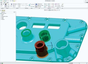
Solid Edge Synchronous Technology Multi-BodySolid Edge ST5 is an exceptionally competent CAD system. If you’re looking for a new CAD system, based solely on its merits, Solid Edge should be on your list of tools to consider.

Yet, there is one case where Solid Edge is not just an alternative, but is the obvious alternative. And that is if you’re considering migrating away from SolidWorks.

This is not a value judgment, or an opinion based on whether or not I like the companies. It’s a technical distinction.

Let me provide a bit of background to explain, first, why I’m even bringing this up, and second, why it is so.

SolidWorks is probably the most successful MCAD program on the market today, in terms of number of customers, users, availability of training, user group support, and a number of other factors. When Dassault Systemes bought the company back in 1997, they got the “goose that laid the golden egg.”

If you’re familiar with the Aesop’s Fable from which that line came, you might know where this is going. For 10 years, Dassault Systemes pretty much let SolidWorks do its own thing. I remember a press conference, where I asked DS President and CEO Bernard Charlès about this, and he said that all he asked of John McEleney (then SolidWorks CEO) was that he “deliver value.”

Charlès is a native French speaker. I assumed at the time that the term “deliver value,” when translated to French then back to English, would mean something like “deliver profits.” And that’s exactly what McEleney did, for many years.

In 2007, McEleney left SolidWorks, and Jeff Ray, formerly the COO, took his position. This changing of the guard signaled a change in the relationship between SolidWorks and Dassault Systemes. Though not obvious at first, it started to become clear that this was the beginning of the process of integrating SolidWorks into DS.

Today, even though much of the old-guard continues on at SolidWorks, there have been some notable defections. Jon Hirschtick, SolidWorks founder, left Dassault last year. Austin O’Malley, who headed up SolidWorks R&D, also left around the same time, and was replaced with Gian Paolo Bassi, who, by all reports, is heavily focused on developing SolidWorks V6. And Jeff Ray, the former SolidWorks CEO who had moved up to the Dassault Systemes Executive Committee, just left as well.

It’s not the same SolidWorks it used to be. The company’s strategy is being driven by Dassault Systemes, from Paris.

Whether the change is a good thing or not is something that only time will tell. Charlès and the other top executives at DS are smart and experienced business people. But they have a different perspective on business than the people who originally ran SolidWorks did.

A couple of years ago, DS SolidWorks previewed a new version of their software, called SolidWorks V6. I wrote about it last February, in the article SolidWorks V6 is not SolidWorks.

SolidWorks V6 is (or, will be) a cloud-based CAD program, built using technology DS originally developed for CATIA and ENOVIA V6. It’s not the same program as today’s SolidWorks program. One distinct difference is the use of the CGM geometric modeling kernel, instead of the Parasolid kernel (which is owned by Siemens PLM.)

At SolidWorks World last February, top managers from DS SolidWorks tried to reassure their customers, saying that they would continue to support the existing desktop version of SolidWorks for as long as customers want to use it. They clarified that they’re going to continue to use the Parasolid geometric modeling kernel in the desktop version, and pointed out that the development team working on SolidWorks 2013 is even bigger than the teams that worked on previous versions.

With these reassurances, SolidWorks users probably ought to feel comfortable about the long-term availability and support of their CAD system of choice. Probably.

Except, there are some things that, taken together, just don’t seem right. At least, to me. To start with, even though Siemens considers Parasolid to be a “level playing field” product, it’s pretty obvious that Dassault thoroughly dislikes having to pay royalties to a competitor to use it. Bernard Charlès is considered the “father of CATIA.” It would be remarkable if he were not highly motivated to move SolidWorks customers over to a plaform based on CATIA technology.

And, what of the SolidWorks 2013 team being “larger?” Numbers there can be deceiving. You can’t measure software development by “man months.” You have to look at the composition of the team. Is it made up mostly of expert-level in-house CAD developers, or is it made up mostly of offshore outsourced developers? Are SolidWorks’ “best people” working on the desktop version, or on the V6 version?

Many reasonable people I know are reading the tea leaves, and believe, based on what they’ve seen so far, that Dassault Systemes’ focus will shift to SolidWorks V6, and away from the desktop version. Not necessarily leaving it as crippleware, but possibly leaving it without the attention it deserves. If that happens, users will have to make some hard choices:

  • Stay with the desktop version of SolidWorks, and hope for the best,
  • Change to SolidWorks V6, or
  • Change to another CAD system.

The costs of changing, whether to SolidWorks V6, or to another CAD system, are not just in software license fees, but also in retraining, and data migration.

Retraining costs may be a wash, whether you go with SolidWorks V6 or another CAD system.

The costs that can get out of control are in data migration between CAD systems using different geometric modeling kernels.

The problem with geometric modeling kernels is that they’re simply not cross-compatible. Not even CGM and ACIS—which are both owned by DS. And certainly not CGM and Parasolid. They vary enough in how they represent and manipulate data that it’s not possible to translate data from one to another with complete (or even entirely predictable) reliability.

(If you’d like to learn a bit more about this, see An Academic View of Interoperability, and A kernel Guru’s View of Interoperability, both at my old blog, at www.evanyares.com.)

There are a number of companies that offer translators that can do a good job of moving data between systems with different kernels. Some of these companies even offer model validation tools, to determine which files didn’t translate correctly. The reasonable estimates I’ve heard place the success rate at around 90 to 95% of files. That means you might only need to manually rebuild 5% to 10% of your CAD files.

That 5% or 10% can add up.  For a medium size company, the costs of manually rebuilding those CAD files can range from hundreds of thousands to millions of dollars.

Consider past experience migrating between different Dassault Systemes CAD programs: The transition from CATIA V4 to CATIA V5 was exceptionally painful for users. Companies that specialize in CAD data validation still make a good chunk of their income from fixing problems in CAD files that have been translated from V4 to V5. And DS has never even offered a native SolidWorks/CATIA translator. There’s no basis to believe that migrating from desktop SolidWorks, which uses the Parasolid kernel, to SolidWorks V6, which will use the CGM kernel, will be painless.

It will be nice, for users, if this concern about SolidWorks turns out to be moot. In the best of all worlds, Dassault would continue to upgrade and maintain the desktop version of SolidWorks. They’d go back and fix the persistent and long-standing bugs and irritations, and add new functionality, such as history-free direct modeling. They’d make sure that the program is a viable tool for a long, long time. They’d serve the needs of the nearly 1.8 million product designers and engineers who count on SolidWorks to work right, so they can do their jobs.

Solid Edge ST5But, if that isn’t how it shakes out, the best option for users may be to consider other CAD systems.

The short list of alternatives isn’t that long.

The ideal alternative would be one that that supports history-free direct modeling, with tools to reparameterize dumb models. It would use the Parasolid geometric modeling kernel, to minimize data conversion issues. It would be priced competitively—in the same range as SolidWorks.  And it would be from a financially sound and well-run firm.

There is only one well-known CAD program that meets those criteria:

Solid Edge.


Filed Under: Siemens PLM Tagged With: Bernard Charles, Catia, CGM, Dassault Systemes, ENOVIA, Parasolid, Solid Edge, SolidWorks

SolidWorks V6 is not SolidWorks

February 22, 2012 By Evan Yares 12 Comments

Two years ago, at SolidWorks World (the show) SolidWorks (the company) showed what appeared to be the next generation of SolidWorks (the software): SolidWorks V6 (also software.)
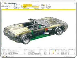
SolidWorks (the company) got major flak from bloggers concerned that SolidWorks V6 (the software) would replace SolidWorks (the software.)

This year, at SolidWorks World (the show), Dassault Systèmes SolidWorks (as the company is now known) didn’t talk much about SolidWorks V6 (the product), other than to say that they’d talk about it in 2013.

Now that we’ve got that all clear, let’s talk about what matters: SolidWorks V6 is confusing branding. It confuses not only users, but even pundits who write about CAD software.

My understanding, after talking to company representatives at SolidWorks World, is that SolidWorks V6 is the name for not just one product, but a future series of products. Those products may incorporate some existing SolidWorks technology, but they’ll be based largely upon CATIA and ENOVIA V6 technology. Because they’ll use the CGM modeling kernel (which was originally written for CATIA V5), they’ll likely be more compatible with CATIA than with today’s SolidWorks.

It makes sense that Dassault Systèmes would want to leverage the strength of the SolidWorks brand for this upcoming series of products. The SolidWorks brand is one of the strongest in the MCAD world. If SolidWorks V6 were actually based on, and entirely compatible with, SolidWorks—the name might fit. But it’s not, and it doesn’t.

The SolidWorks V6 name creates unnecessary fear, uncertainty, and doubt among SolidWorks users who are concerned that they’ll be forced to transition from a CAD program they know and (sometimes) love to this new technology, whether they want to or not.

What’s particularly unfortunate is that, if Dassault Systèmes had originally used a code name for the technology instead of calling it SolidWorks V6, they never would have created this whirlwind of FUD among their users. People might have seen it as just what it is: A really interesting future product, that they might want to add to their portfolio of CAD tools some day (when it’s ready.)

The bottom line is that the new technology called SolidWorks V6 isn’t SolidWorks, and won’t replace SolidWorks. According to Fielder Hiss, SolidWorks VP of Product Management, the development team working on SolidWorks 2013 is even larger than the teams that worked on previous versions.

The real SolidWorks—the CAD program now used by about 1.7 million people—is going to be around for a long time.

Filed Under: Evan Yares, Featured, SolidWorks, SolidWorks News & Events Tagged With: Catia, Dassault Systemes, ENOVIA, Evan Yares, SolidWorks, V6

Michigan Autonomous Aerial Vehicle robots take flight

January 18, 2012 By Laura Carrabine Leave a Comment

Danny Ellis was first introduced to CAD in high school with a course in Autodesk Inventor. As he advanced into the engineering program at the University of Michigan, he was introduced to CATIA.

“In between my freshman and sophomore years, I became irritated at how cumbersome it was to rotate a model using a traditional mouse. I thought I could get a trackball mouse and program it so when I rotate the mouse it rotates the part on screen. That’s when I came across 3Dconnexion. I ordered their SpaceNavigator right away,” said Ellis.

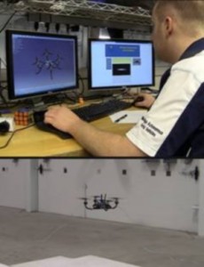
In 2009 during his senior year, Ellis began researching an aerial robot competition. Five days later, he started the Michigan Autonomous Aerial Vehicles (MAAV) team with 15 members. Within one week, the team kicked off their first quadrotor design for the International Aerial Robotics Competition (IARC). At the end of the first year, MAAV successfully built two quadrotor vehicles capable of manual flight.

“The IARC challenge is to build a flying robot of any type you want. We chose a four-rotor helicopter that can fly through an unknown building completely on its own,” added Ellis. “There can be no communication with the device. The robot follows signs, must avoid detection from security cameras, locate a room, retrieve a flash drive, drop off the decoy, and get out in less than 10 minutes. No one has completed the mission yet, but we are one of the better teams competing. It’s the most challenging mission to date.”

When Ellis started the team, he wanted to get a 3Dconnexion 3D mouse for everyone. “It makes modeling CAD designs so much faster and easier,” said Ellis. IN addition, the team quickly realized trying to fly the quadrotor with a standard joystick didn’t mimic the movements very well and wasn’t intuitive enough for the user. A 3D mouse could mimic the exact movement of the robot. It was at this point the team decided to take matters into their own hands and control flight with a 3D mouse.

“We use the 3Dconnexion SDK to develop a driver to control the quadrotor with the SpaceExplorer and it quickly allowed us to control pitch and roll, zoom control height, and rotation control yaw,” noted Ellis. “In addition, The SpaceExplorer’s Intelligent Function Keys control other commands such as on/off and camera control.”

Today, Ellis is still the head of the MAAV team while also completing two masters in aerospace engineering and robotics. He continues to use CATIA for all of his designing both for the team and his class projects. He also works at a student lab training other students involved in competitions in CAD modeling and machining.

He uses the SpacePilot Pro. “A 3D mouse allows me to easily interact with the model while clicking and drawing in 3D at the same time,” he said.

3Dconnexion

www.3dconnexion.com


Filed Under: 3D CAD Package Tips, Catia, Catia Blogs, Catia News & Events Tagged With: 3D, 3Dconnexion, cad, Catia, Danny Ellis, IARC, Inventor, MAAV, Michigan, robotics, SpaceExplorer, SpaceNavigator

Ice Dream: Towing an iceberg for fresh water

January 10, 2012 By Laura Carrabine Leave a Comment

“With the world’s water resources projected to diminish by one third in the next two decades, providing pure water to an ever- increasing world population is vital,” Mougin explained. To Mougin and Mauviel, one solution would be to transport icebergs to areas that lack fresh water for drinking and even cooling purposes. The scientific challenges are impressive — capturing a large iceberg that can weigh up to 7 million tons, protecting it from melting while transporting it across the ocean, securing and optimizing the trajectory with respect to meteorological and oceanographic conditions, and breaking up the iceberg to turn it into drinking water.

Dassault Systèmes worked with Mougin and his team to simulate the iceberg’s trajectory and its evolution by taking into account data such as variations in ocean temperatures, wind force and direction, sea currents, and boat drag force. They inserted this data into a 3D model of the iceberg to simulate what would happen all along the voyage.

The critical challenge presented to Dassault Systèmes’ engineers was to demonstrate, using virtual technology, the technical feasibility of displacing the iceberg in a controlled manner while reducing its melting. The project, managed by Cédric Simard, Interactive Strategy & Marketing Project Director at Dassault Systèmes, involved a number of steps:

  1. Model the iceberg with CATIA based on a cloud of points obtained by scanning a real iceberg with radar.
  2. Calculate and simulate the way the iceberg would melt using CATIA Systems and SIMULIA.
  3. Simulate the way the iceberg would melt if surrounded by a protective isothermal “skirt” imagined by Mougin to slow the melting process.
  4. Calculate how much fuel the boats would consume depending on the winds and currents encountered along the way

Various scenarios were simulated, such as number of boats needed, different departure dates and climate conditions, and the behavior of the boats and iceberg in the event of a storm or turbulence. In addition to enabling the team to visualize these scenarios, the simulation also allowed the scientists to test how to deploy the isothermal skirt around the iceberg.

Dassault Systemes

www.3ds.com

Filed Under: Catia, Catia Blogs, Featured, PTC News, Simulation Software Tagged With: Catia, Dassault, Simulia

New software slated to change the workplace

January 3, 2012 By Laura Carrabine Leave a Comment

CAD software vendors have touted product usability for a long time. However, they haven’t really delivered on that promise until recently. There were a few software debuts in 2011 that changed that premise. True user usability could lead to a broader CAD audience and a bigger market share.

The product development team at PTC came up with the idea of a creating single program that does everything versus offering diverse programs with no connectedness. The strategy addresses its customer base and the trend toward solid modeling for the masses. Creo 1.0 is the result of that concept. The software currently has nine applications including Creo Parametric, Direct, Illustrate, Schematics, View MCAD, View ECAD, Sketch, and Layout.

The company focused on a group of traditional user problems and applied a core of technologies against them, specific roles having options for modeling modes with the click of an app. Simplifying a process that has plagued engineers and designers for decades makes using the software and being productive all the difference. The Creo GUI is much cleaner than the Pro/E GUI. According to those who have used the new product, the GUI strategy is most evident in Creo Parametric and Creo Direct. PTC leveraged the best features from CoCreate and made it easier to use. The company added features to Creo Parametric that will make Pro/E seem like ancient technology. Creo proves that a feature can live in a history-based and history-free environment keeping the parametric relation to features within each if needed.

Another 2011 debut was SolidWorks 2012 that also sports new features to help a more diverse audience. The software has improvements in assembly and drawing capabilities, built-in simulation, design costing, routing, image and animation creation, and product data management. Dassault Systemes says SolidWorks 2012 will help automate design functions, change product development processes, and extend support for collaboration and connectivity. This technology could change how the software is marketed and sold. The product helps users streamline design processes by removing traditional steps.

Autodesk’s AutoCAD 2012 and Design Suite 2012 series are available in a range of offerings including web and mobile applications. Thus more users have access to the technology and can stay connected to their work no matter where they are.  In addition, AutoCAD 2012 and Design Suite 201212 are directly connected to the free AutoCAD WS web and mobility application.

With CAD pretty much saturating the engineering and manufacturing arena, CAD vendors are realizing that pumping out a redressed version of what went out the door at the last launch is not going to work much longer. They have to offer tools that appeal to other audiences. We have seen that starting to happen in the retail, hobby, and jewelry industries where non-engineering types are using 3D programs to crank out new products.

PTC
www.ptc.com

Dassault Systemes
www.3ds.com

Autodesk
www.autodesk.com

Filed Under: Autocad Blogs, Autodesk, Autodesk News, Catia, Catia Blogs, Catia News & Events, PTC News, SolidWorks, SolidWorks Blogs, SolidWorks News & Events Tagged With: 3D CAD, AutoCAD, Autodesk, Catia, Design Suite, PTC Creo, SolidWorks

Sea monster of a yacht

September 21, 2011 By Laura Carrabine Leave a Comment

The Volvo Ocean Race for 2011-2012 includes 70-ft Mar Mosto, the “Monster of the Sea” entry. Designed by Juan Yacht Design of Valencia, Spain and constructed at New England Boatworks in Portsmouth, RI, the mono-hull was created to sail around the world and face extreme conditions.

The yacht weighs approximately 15 tons and will reach speeds up to 40.5 knots (46.6 mph) during the race. According to designer Juan Kouyoumdjian, the design process was divided into two sections: research and development and manufacturing. His team used Catia software as the basis of the 3D modeling, Hyperworks for the structural analysis, and Star CCM for all the CFD work such as hydrodynamics, aerodynamics, and structures.

For the 2011-2012 race, Puma Ocean Racing partnered with Berg Propulsion, a leading designer and producer of controllable pitch propellers for commercial shipping. During the nine months of the Volvo Ocean Race which starts in Alicante, Spain in November 2011 and concludes in Galway, Ireland in July 2012, the teams will sail more than 39,000 nautical miles.

Other interesting facts about Mar Mosto

Mast height: 105 ft
Boom length: 28.5 ft
Total sail area: 2,215 sq ft
Mainsail area: 1,884 sq ft
Spinnaker area: 5,384 sq ft
Boat material: carbon fiber
Sail material: Aramid/Spectra Blend
Build hours: 39,536
Paint hours: 600

Puma Ocean Racing
www.pumaoceanracing.com

Dassault Systemes
www.3ds.com

Altair
www.altair.com

CD-Adapco
www.cd-adapco.com

Filed Under: 3D CAD Package Tips, CAD Package, Catia, Catia News & Events, Simulation Software Tagged With: Altair, Catia, CD-Adapco, Dassault, Hyperworks, Juan Yacht Design, New England Boatworks, Puma, Star CCM 3C CAD, Volvo

Software for manufacturing

August 23, 2011 By Laura Carrabine Leave a Comment

Sigmasoft simulates the following processes: filling, packing, cooling, venting, shrinkage, warpage, stress, ejection, post molding, hot runners, multi-cycle, multi-component, and insert over-molding.

Sigmasoft filling and packing simulation predicts temperatures, pressures, velocities, crystallization, and shearing at any location at any time to determine manufacturability and ensure a balanced mold design. Weld lines, sink marks, voids, and air traps are also valuable outputs to eliminate the potential for part defects.

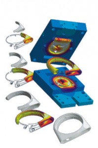
The thermal distribution inside an injection mold depends on many factors. In the same way as the polymer flows three dimensionally into the cavity, the heat also flows three dimensionally between inserts, part, mold, and thermal control. A multi-cycle analysis enables you to simulate the quasi-stationary state of a m old including all local temperature differences and consequently to perform a much more precise filling simulation based on the steady state temperature distribution. Sigmasoft accurately calculates the complex thermal distribution in the mold coupled with polymer flow.

The software simulates the impact of the ejection system on the part and offers insight into the ejection system design. Ejection forces are predicted to understand their impact on final part quality. The ejection system may also be evaluated to determine the porper quantity of ejector pins.

Proper venting is critical to the injection molding process. Without proper venting, quality and flow imbalances are common issues. Sigmasoft lets you model vents into the simulation to optimize location and size, and view the impact of trapped air on the flow front. View trapped air pockets, air pressure, and air temperature in the cavity.

The software predicts post-ejection stress relaxation and crystallization of the part which often provides a more accurate warpage prediction. A second heat cycle may also be simulated, taking into account the entire process history.

3D CAD models of the part geometry and the entire mold if needed can be imported directly into Sigmasoft in multiple formats including STEP, STL, SAT, Pro/E, or Catia. The software also includes tracer particles to help visualize what is happening behind the flow front. These tracers are shown during the filling, packing, and cooling processes.

Sigmasoft

www.3dsigma.com

Filed Under: Simulation Software Tagged With: 3D CAD, analysis, Catia, plastic injection molding, Pro/E, Sigmasoft, simulation, warpage

  • Go to page 1
  • Go to page 2
  • Go to Next Page »

Primary Sidebar

3D CAD NEWSLETTERS

MakePartsFast

Footer

3D CAD World logo

DESIGN WORLD NETWORK

Design World Online
The Robot Report
Coupling Tips
Motion Control Tips
Linear Motion Tips
Bearing Tips

3D CAD WORLD

  • Subscribe to our newsletter
  • Advertise with us
  • Contact us
Follow us on Twitter Add us on Facebook Add us on LinkedIn Add us on Instagram Add us on YouTube

3D CAD World - Copyright © 2022 · WTWH Media LLC and its licensors. All rights reserved.
The material on this site may not be reproduced, distributed, transmitted, cached or otherwise used, except with the prior written permission of WTWH Media.

Privacy Policy