• Skip to primary navigation
  • Skip to main content
  • Skip to primary sidebar
  • Skip to footer

3D CAD World

Over 50,000 3D CAD Tips & Tutorials. 3D CAD News by applications and CAD industry news.

  • 3D CAD Package Tips
    • Alibre
    • Autodesk
    • Catia
    • Creo
    • Inventor
    • Onshape
    • Pro/Engineer
    • Siemens PLM
    • SolidWorks
    • SpaceClaim
  • CAD Hardware
  • CAD Industry News
    • Company News
      • Autodesk News
      • Catia News & Events
      • PTC News
      • Siemens PLM & Events
      • SolidWorks News & Events
      • SpaceClaim News
    • Rapid Prototyping
    • Simulation Software
  • Prototype Parts
  • User Forums
    • MCAD Central
    • 3D CAD Forums
    • Engineering Exchange
  • CAD Resources
    • 3D CAD Models
  • Videos

3D

Electromagnetic design tool provides short route to motor perfection

February 1, 2012 By Laura Carrabine 2 Comments

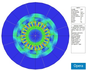
Cobham’s Machines Environment introduced a new level of user friendliness when it was launched by providing a design entry system that allows precision FEA models of motors and generators to be created and solved in minutes. The 2D version of the software has now been integrated with Cobham’s optimization tool which automatically finds the optimal solution within a design space – even for multiple or competing design objectives.

The software is an application-specific extension to the Opera electromagnetic simulation package. It provides a front-end to the simulator that speeds design entry by means of Wizard-style dialog boxes. Users select the style of motor or generator they want to design from a library of all common types, including induction, brushless permanent magnet and switched reluctance motors, and synchronous motors or generators. Then, dialog boxes allow you to enter parameters to define mechanical geometry, material properties and electrical data, and the FEA model is automatically created.

The use of parameterized models and the ability to load and modify previous designs have made it possible for users to perform ‘what-if?’ design investigations. Cobham has integrated a unique optimization tool that makes it simple for users to find the best solution across the design space. While auto-optimization tools are not new, they usually require manual intervention if the globally optimal solution is to be found, and the simulation times involved often make this impractical. The Optimizer selects and manages multiple goal-seeking algorithms including stochastic, descent, particle swarm, and Kriging to eliminate the need for manual intervention.

Setting up an Optimizer run from the Machines Environment is easier. Because most FEA simulations can take as little as a few seconds, the integrated software makes it possible to thoroughly explore the design space. Thousands of simulations can typically be executed within hours, making the perfect solution achievable for all users – without expert assistance.

 The 2D Machines Environment has an extensive library of rotating machine design styles and design components. However, if there are still any unusual features that need to be incorporated in designs, users also have open access to the scripts that generate the models, and can modify them at will to automate proprietary motor and generator design concepts. A library of common material properties is also included in the design software. Again, if users employ any special materials, such as an unusual grade of steel for laminations, then a new menu item can be created. Cobham will also generate custom scripts for users on request. A 3D version of the Machines Environment is available.

Cobham Technical Services

www.cobham.com/technicalservices


Filed Under: 3D CAD Package Tips, CAD Industry News, CAD Package, Simulation Software Tagged With: 2D, 3D, Cobham Technical Services, FEA, Machines Environment, Opera, Optimizer

Michigan Autonomous Aerial Vehicle robots take flight

January 18, 2012 By Laura Carrabine Leave a Comment

Danny Ellis was first introduced to CAD in high school with a course in Autodesk Inventor. As he advanced into the engineering program at the University of Michigan, he was introduced to CATIA.

“In between my freshman and sophomore years, I became irritated at how cumbersome it was to rotate a model using a traditional mouse. I thought I could get a trackball mouse and program it so when I rotate the mouse it rotates the part on screen. That’s when I came across 3Dconnexion. I ordered their SpaceNavigator right away,” said Ellis.

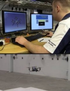
In 2009 during his senior year, Ellis began researching an aerial robot competition. Five days later, he started the Michigan Autonomous Aerial Vehicles (MAAV) team with 15 members. Within one week, the team kicked off their first quadrotor design for the International Aerial Robotics Competition (IARC). At the end of the first year, MAAV successfully built two quadrotor vehicles capable of manual flight.

“The IARC challenge is to build a flying robot of any type you want. We chose a four-rotor helicopter that can fly through an unknown building completely on its own,” added Ellis. “There can be no communication with the device. The robot follows signs, must avoid detection from security cameras, locate a room, retrieve a flash drive, drop off the decoy, and get out in less than 10 minutes. No one has completed the mission yet, but we are one of the better teams competing. It’s the most challenging mission to date.”

When Ellis started the team, he wanted to get a 3Dconnexion 3D mouse for everyone. “It makes modeling CAD designs so much faster and easier,” said Ellis. IN addition, the team quickly realized trying to fly the quadrotor with a standard joystick didn’t mimic the movements very well and wasn’t intuitive enough for the user. A 3D mouse could mimic the exact movement of the robot. It was at this point the team decided to take matters into their own hands and control flight with a 3D mouse.

“We use the 3Dconnexion SDK to develop a driver to control the quadrotor with the SpaceExplorer and it quickly allowed us to control pitch and roll, zoom control height, and rotation control yaw,” noted Ellis. “In addition, The SpaceExplorer’s Intelligent Function Keys control other commands such as on/off and camera control.”

Today, Ellis is still the head of the MAAV team while also completing two masters in aerospace engineering and robotics. He continues to use CATIA for all of his designing both for the team and his class projects. He also works at a student lab training other students involved in competitions in CAD modeling and machining.

He uses the SpacePilot Pro. “A 3D mouse allows me to easily interact with the model while clicking and drawing in 3D at the same time,” he said.

3Dconnexion

www.3dconnexion.com


Filed Under: 3D CAD Package Tips, Catia, Catia Blogs, Catia News & Events Tagged With: 3D, 3Dconnexion, cad, Catia, Danny Ellis, IARC, Inventor, MAAV, Michigan, robotics, SpaceExplorer, SpaceNavigator

MSC Software’s Patran and Marc software used in cellular research at Clemson University

January 10, 2012 By Laura Carrabine Leave a Comment

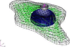
The goal of this study is to construct a representative 3D finite element model of a biological cell based on the sub-cellular structures that provide the cell with its mechanical properties. The geometries for the model are constructed from 3D microscope images of cells using proprietary analytical algorithms, imported into Patran for pre-processing, and submitted to Marc for analysis. Vascular smooth muscle cells (VSMCs) are chosen for the study due to the strong correlation of the geometric arrangement of their structural components on their mechanical behavior and the implications of that behavior on diseases such as atherosclerosis.

The ability to model the mechanical responses of cells to physical stimuli presents many opportunities to the world of medical research. Chief among these is the ability to further our understanding of the etiology of many diseases. There are a wide variety of diseases whose etiology or clinical presentation are either known or suspected to be related to abnormal cellular mechanics, alteration of the cellular processes that regulate transmission of mechanical stimuli into biochemical responses, or changes in tissue structure. Because physical distortion can affect cell how cells grow, specialize themselves for specific tasks, move, and whether they live or die, the ability to predict the mechanical behavior of cells in response to pathological conditions and medical treatments may be critical to prevention and treatment of many of these diseases.

VSMCs are modeled here using a linear elastic material model together with truss elements in Marc which simulate the cytoskeletal fiber network that provides the cells with much of their internal structural support. Geometric characterization of single VSMCs in 2D cell culture is achieved using confocal microscopy in conjunction with novel image processing techniques. These techniques allow for the creation of representative 3D model structures consisting of the cell nucleus, cytoplasm, and actin stress fiber network of each cell, which are then imported into Patran for structural analysis with Marc. Mechanical characterization is achieved using atomic force microscopy (AFM) indentation and stress relaxation techniques. Material properties for each VSMC model are input based on values individually obtained through experimentation, and the results of each model are compared against those experimental values.

This study is believed to be a significant step towards the viability of finite element models in the field of cellular mechanics because the geometries of the cells in the model are based on confocal microscopy images of actual cells with mechanical data obtained immediately prior to imaging and thus, the results of the model can be compared against experimental data for those same cells. These types of models could one day be used to decrease the cost and speed the development of new drug discovery and regenerative medicine therapies, as well as increase our understanding of the relationship between the structure and function of biological cells.

MSC Software

www.mscsoftware.com

Filed Under: Simulation Software Tagged With: 3D, Clemson, Marc, MSC Software, Patran, simulation

Printer shifts from 2D to 3D

December 22, 2011 By Laura Carrabine Leave a Comment

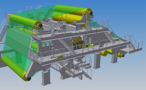
Voith Paper decided to improve its design process across its centers of competencies around the world. Each center specializes in particular parts of a paper machine: due to its massive size and complexity, a finished machine requires design input from several design centers. Voith knew that speeding up its design and manufacturing processes would mean aligning its dispersed design teams.

Moving its designers onto a standard platform worldwide meant integrating the Autodesk manufacturing technology with other key enterprise systems. As a result, Voith has synchronized its design teams and achieved new heights in speed and efficiency levels. “By integrating our 3D models into our SAP ERP system, we can make design changes more quickly. Every engineer has access to the same information, said Voith’s Olaf Spitzer. “This allows us to respond to our customers’ needs faster.”

Frederich Spitzer, PDM Support Manager, IT Solutions for Voith, “We are organized into centers of competencies, so every location with manufacturing capabilities has competencies for a certain product in the finished machine. By installing a common Inventor SAP ERP system with help from Autodesk Consulting, we bring all the information that is generated by these different locations together in one system.”

Voith is also gaining efficiencies associated with the enterprise parts management system built by Cadenas GmbH. The PART system reduces design time by providing access to components and assemblies. Design and development engineers are able to see relevant part information such as price, delivery time, and release status in one user interface.

With a common database, Voith’s design team now uses the same items with the same information. By streamlining parts numbers, Voith facilitates procurement, inventory, and maintenance.

Today, Voith is creating more accurate designs faster. Each machine is designed by several of Voith’s centers of competencies and then assembled at the customer site. Since adopting Inventor, Voith has reduced assembly problems.

“By integrating Inventor with our ERP system, we can respond quicker to our customer needs,” said Olaf Spitzer. “We are able to show them designs before we build a machine. For one project in China, a company ordered parts of a paper machine. We showed them the design and they had changes which we were able to make overnight. We then presented the new design to the customer the next day and secured an order.”

Autodesk

www.autodesk.com

Filed Under: Autodesk, Autodesk News, Inventor Tagged With: 2D, 3D, Autodesk, Cadenas, ERP, Inventor, SAP, Voith Paper

Surface deformation software

December 15, 2011 By Laura Carrabine Leave a Comment

Kickstand launched a campaign to evolve StretchMesh Surface Deformation software into Open Source technology – opening the door for artists working in Maya to incorporate the surface deformation technology into their 3D workflow. The initiative allows programmers and developers of software programs such as Autodesk 3D Studio Max and Softimage, NewTek LightWave, Luxology modo, and Maxon Cinema 4D to incorporate advanced surface deformation functionality in future product releases.

StretchMesh introduces new techniques and gives polygonal geometry a “stretch” quality for better control over the movement and skin elasticity of 3D modeled characters. The software features advanced relational vertex and shape preservation technology, offering animators and technical directors working in feature film, broadcast, and game development the ability to create smooth character deformations using Maya software.

StretchMesh takes advantage of multi-threading in Maya software, and incorporates several features for advanced character animation including greater flexibility and performance when animating collisions with primitive sphere and primitive curve colliders, the ability to pain an influence on a collision object for per-vertex control over collision behaviors, curve attractors provide the ability to pull vertices toward the closest point on  a curve, and a “Scale Safe” mode that allows users to scale a mesh while safely preserving its initial shape.

Kickstand

www.kickstand.tv

Filed Under: 3D CAD Package Tips, Autodesk, Autodesk News Tagged With: 3D, Autodesk, Cinema 4D, Kickstand, Luxology, Maya, modo, NewTek LightWave, Softimage, StretchMesh

AAC Engineered Systems

December 7, 2011 By Laura Carrabine Leave a Comment

The company focuses on heavy-duty applications and advanced material handling. The company was using a 2D design package and decided to move to a 3D CAD system to gain greater flexibility in designing equipment to meet customer requirements.

AAC’s engineers attended the Chicago Machine Design Show and reviewed every CAD system being demonstrated. They were most impressed with SolidWorks because it is based on mechanical design

According to a company spokesperson, “SolidWorks software has revolutionized our engineering department. Configuration Management enables us to reuse existing designs in creating custom-made equipment. We try out different “what-if” configurations, checking for interferences and fit-on-screen, not on the production floor. Smart Part Technology knows which fasteners go into which holes and puts them there. We can design sheet-metal parts accurately without first machining them, saving time and reducing scrap. Our designers create the models, and SolidWorks makes the drawings, allowing us to conserve technical resources. And, eDrawings helps us market to and communicate with customers.”

SolidWorks

www.solidworks.com

Filed Under: 3D CAD Package Tips, CAD Industry News, SolidWorks, SolidWorks Blogs, SolidWorks News & Events Tagged With: 2D, 3D, AAC Engineered Systems, cad, Configuration Management, eDrawings, Smart Part Technology, SolidWorks

CAD for the stars

August 22, 2011 By Laura Carrabine Leave a Comment

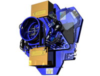
The WIYN Observatory is owned and operated by the WIYN Consortium, which consists of the University of Wisconsin, Indiana University, Yale University, and the National Optical Astronomy Observatory (NOAO). The WIYN Observatory enables frontier astrophysical research through the design of astronomical instrumentation (such as an imager or spectrograph). The primary challenge is developing an instrument that delivers the image quality that the astronomy community requires while meeting the budgetary and schedule constraints of the project. Engineers have to be able to design, analyze, and produce fabrication drawings of the components of the instrument.

The WIYN Consortium chose SolidWorks software as its primary mechanical design software based on its reliability, ease of use, ease of learning, and reasonable price. SolidWorks Simulation was chosen based on its interface with SolidWorks CAD software. Predictable behavior when constraining sketches, three-file architecture, dynamic rotation, easy movement of part files from one assembly to another by dragging and dropping, and dissolving and forming subassemblies were some of the reasons why the consortium chose the products.

Researchers used the software to develop the One Degree Imager (ODI), a wide-field, giga-pixel camera slated for use on the WIYN 3.5-meter telescope located at Kitt Peak National Observatory near Tucson, Ariz. During the project, designers and engineers shortened the design cycle by approximately 20%, saved up to $300,000 in development costs, and reduced drafting time by nearly 50%.

SolidWorks

www.solidworks.com

Filed Under: 3D CAD Package Tips, CAD Package, SolidWorks, SolidWorks Blogs, SolidWorks News & Events Tagged With: 3D, cad, simulation, SolidWorks, WIYN

Autodesk launches AutoCAD products for the Mac OS X Lion

August 16, 2011 By Laura Carrabine Leave a Comment

Autodesk debuted three products for the Mac operating environment: AutoCAD 2012, AutoCAD LT 2012, and AutoCAD WS.

AutoCAD 2012 for Mac includes 2D and 3D tools, 3D free-form modeling, 3D visualization and rendering, network licensing, advanced customization of menus, and support for LISP, ObjectARX, and ObjectDBX.

AutoCAD LT for Mac follows common Mac application UI guidelines with an Apple menu bar with workflow-based palettes. The software supports native Mac OS X behavior including Cover Flow navigation and Multi-Touch gestures.

AutoCAD WS for Mac is a free app that provides basic tools for viewing, editing,a nd sharing designs. Through its synchronous coediting feature, uou can collaborate on designs across multiple platforms —  desktop, mobile, and web.

AutoCAD for Mac 2012 is free to students and educators through the Autodesk Education Community where more than 25 Autodesk software products are available for download.

AutoCAD for Mac 2012 and AutoCAD WS for Mac will be available worldwide August 19, 2011. AutoCAD LT for Mac will only be available in the U.S. and Canada on August 16, 2011. AutoCAD LT for Mac and AutoCAD WS for Mac will be delivered exclusively as apps on the Mac App Store.

Autodesk

www.autodesk.com

Filed Under: 3D CAD Package Tips, Autocad Blogs, Autodesk, Autodesk News, CAD Package Tagged With: 2D, 3D, Apple, AutoCAD, AutoCAD 2012, AutoCAD LT, AutoCAD WS, Autodesk, Mac

PTC Releases Windchill 10.0

April 7, 2011 By Laura Carrabine Leave a Comment

PTC announced the release of Windchill 10.0, its product lifecycle management (PLM) software. With new capabilities that focus on product analytics and quality management, Windchill 10.0 allows you to define, manage, and validate complete bills of material (BOMs), providing linkages across domain-specific views of product structures throughout the entire lifecycle. The product is said to be easier to use and maintain. Users managing product structures in Windchill 10.0 can take advantage of embedded visualization.

Windchill centrally manages all product deliverables including MCAD, ECAD, documentation, and service information. The product unifies its ECAD data management capabilities to offer a common user experience, consistent with its existing approach for MCAD data management.

When combined with Creo for 3D illustrated and animated service instructions and parts lists, and Arbortext for technical communications creation and delivery, Windchill supports a complete service information solution. The software supports business process optimization, most notably for Detailed Design, Variant Design and Generation, and Verification and Validation.

With Windchill 10.0, PTC’s Relex and Insight product lines have been rebranded as part of the Windchill product family to better reflect their availability as both a stand-alone offering as well as part of a comprehensive Windchill solution. 

Windchill Quality Solutions (including the former Relex products) help improve next-generation products, prevent repeat errors, and build reliability and risk management into the product development lifecycle. New offerings include solutions for CAPA (Corrective Action Preventive Action) to accelerate problem resolution through improved monitoring and root cause identification. 

Windchill Product Analytics (formerly InSight) provides early knowledge of product performance and includes new solutions for cost visibility and carbon footprint analysis. These enhancements bolster an already rich solution for materials and substance management, which includes reporting against compliance specifications such as REACH and RoHS. These solutions help companies understand environmental impacts and address potential points of failure before they occur. 

PTC

www.ptc.com

Filed Under: CAD Industry News, Pro/Engineer, PTC News Tagged With: 3D, Arbortext, Creo, ECAD, InSight, MCAD, PLM, PTC, Windchill

Dassault Systèmes’ 3DVIA turns virtual world into stereoscopic 3D experience

March 8, 2011 By Laura Carrabine Leave a Comment

Dassault Systèmes announced that users of 3DVIA Scenes, a free online 3D publishing application, can share their creations in fully immersive stereoscopic 3D. With this update, over 230,0003DVIA.com content creators can interact inside their applications online or through PC-connected TVs using anaglyph (red/blue), side-by-side, line-by-line or checkerboard-capable 3D glasses.

3DVIA Scenes is a powerful, yet easy-to-use, Web-based 3D publishing application. With a library of pre-made 3D environments and models, anyone can create and publish realistic and interactive multi-user applications to his or her Website or Facebook page. To activate stereoscopic 3D, simply click a button within the 3DVIA Scenes application and toggle between anaglyph, side-by-side, line-by-line and checkerboard viewing cameras. The functionality is publically available on 3DVIA.com at www.3dvia.com/scenes.

Dassault Systemes

www.3ds.com

Filed Under: 3D CAD Package Tips, CAD Industry News, Design World, Simulation Software Tagged With: 3D, 3DVIA, Dassault Systemes, visualization

  • Go to page 1
  • Go to page 2
  • Go to page 3
  • Go to Next Page »

Primary Sidebar

3D CAD NEWSLETTERS

MakePartsFast

Follow us on Twitter

Tweets by 3DCADWorld

Footer

3D CAD World logo

DESIGN WORLD NETWORK

Design World Online
The Robot Report
Coupling Tips
Motion Control Tips
Linear Motion Tips
Bearing Tips

3D CAD WORLD

  • Subscribe to our newsletter
  • Advertise with us
  • Contact us
Follow us on Twitter Add us on Facebook Add us on LinkedIn Add us on Instagram Add us on YouTube

3D CAD World - Copyright © 2021 · WTWH Media LLC and its licensors. All rights reserved.
The material on this site may not be reproduced, distributed, transmitted, cached or otherwise used, except with the prior written permission of WTWH Media.

Privacy Policy