• Skip to primary navigation
  • Skip to main content
  • Skip to primary sidebar
  • Skip to footer

3D CAD World

Over 50,000 3D CAD Tips & Tutorials. 3D CAD News by applications and CAD industry news.

  • 3D CAD Package Tips
    • Alibre
    • Autodesk
    • Catia
    • Creo
    • Inventor
    • Onshape
    • Pro/Engineer
    • Siemens PLM
    • SolidWorks
    • SpaceClaim
  • CAD Hardware
  • CAD Industry News
    • Company News
      • Autodesk News
      • Catia News & Events
      • PTC News
      • Siemens PLM & Events
      • SolidWorks News & Events
      • SpaceClaim News
    • Rapid Prototyping
    • Simulation Software
  • Prototype Parts
  • User Forums
    • MCAD Central
    • 3D CAD Forums
    • Engineering Exchange
  • CAD Resources
    • 3D CAD Models
  • Videos

FEA

MIT Spinoff Speeds Simulation of Large Structures

September 3, 2014 By Barb Schmitz Leave a Comment

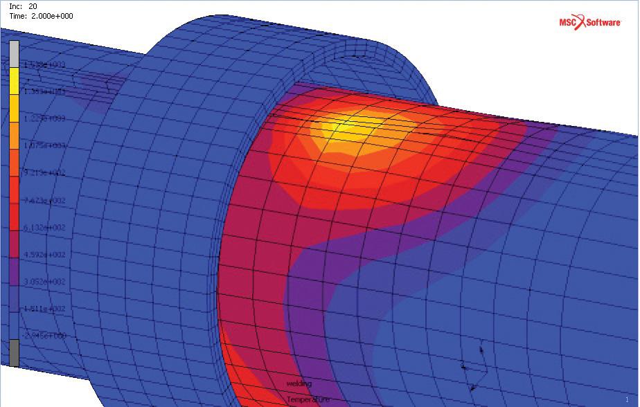
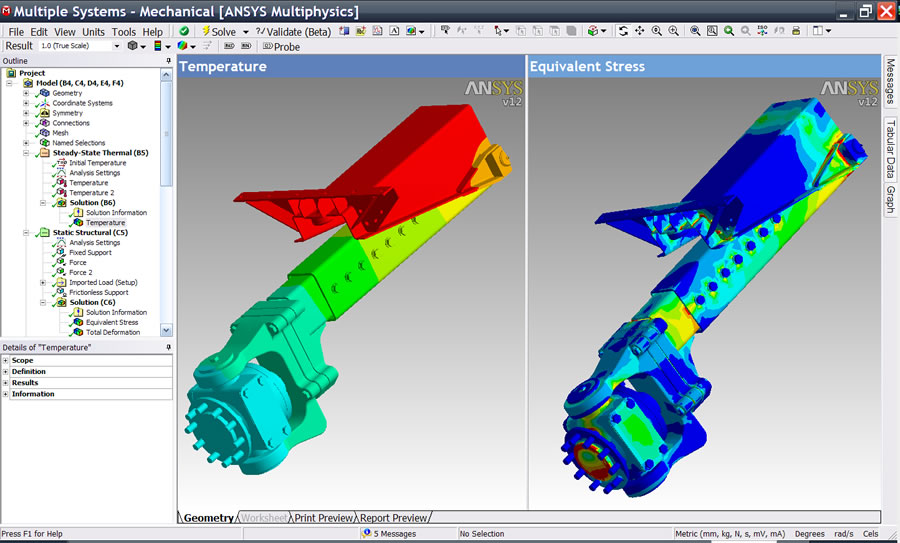
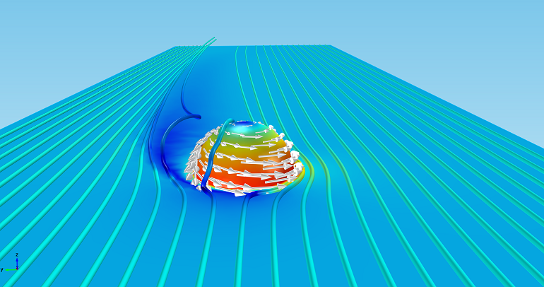
In product development, simulation technology, such as finite element analysis (FEA), is commonly used to test how products will behave and perform under a range of real-world conditions (stress, heat, vibration, etc.) while those product still remain in digital form.

The challenge of modeling and simulating large-scale structures, such as mining equipment, buildings, and oil rigs, is the sheer amount of data crunching, or computation, involved. Running these mammoth-size models through a simulation program can take many hours of computing time even on expensive systems, which requires significant resources in terms of time and money.

Making large-scale simulations faster

MIT spinoff Akselos has been working to make the process more efficient. The Akselos team, which includes CTO David Knezevic, cofounder and former MIT postdoc Phuong Huynh as well as MIT alumnus Thomas Leurent, developed innovative software based on years of research at MIT.

The software relies on precalculated supercomputer data for structural components, like simulated Legos, to significantly reduce simulation times. According to an article on the MIT news site, a simulation that would take hours with traditional FEA software can be carried out in seconds with the Akselos method.

The startup has attracted hundreds of users from the mining, power-generation, and oil and gas industries. An MIT course on structural engineering is introducing the software to new users as well.

The Akselos team is hoping that its technology will make 3D simulations more accessible to researchers around the world. “We’re trying to unlock the value of simulation software, since for many engineers current simulation software is far too slow and labor-intensive, especially for large models,” Knezevic says. “High-fidelity simulation enables more cost-effective designs, better use of energy and materials, and generally an increase in overall efficiency.”

FEA assisted by the cloud

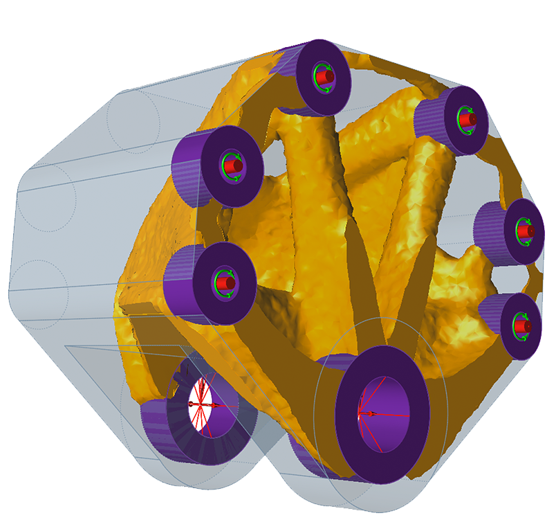
The software runs in tandem with a cloud-based service. A supercomputer precalculates individual components of the model, and this data is pushed to the cloud. The components have adjustable parameters, so engineers can fine-tune variables such as geometry, density, and stiffness.

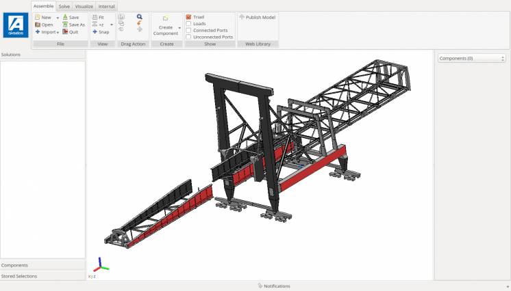
After creating a library of precalculated components, the engineers drag and drop them into an “assembler” platform that links the components. The software then references the precomputed data to create a highly detailed 3D simulation in seconds.

New simulation software developed by an MIT spinoff relies on precalculated supercomputer data for structural components — like simulated Legos — to significantly reduce simulation times.

By using the cloud to store and reuse data, algorithms can finish more quickly. Another benefit is that once the data is in place, modifications can be carried out in minutes.

The roots for the project extend back to a novel technique called the reduced basis (RB) component method, co-invented by Anthony Patera, the Ford Professor of Engineering at MIT, and Knezevic and Huynh. This work became the basis for the 2010-era “supercomputing-on-a-smartphone” innovation, before morphing into its current incarnation under the Akselos banner.

Barb Schmitz

Filed Under: CAE, General Blogs Tagged With: 3D digital model, FEA, MIT

MSC Rolls Out New Releases of Marc 2014 and Adams 2014

August 27, 2014 By Barb Schmitz Leave a Comment

The developers at MSC Software have been busy this summer. The Newport Beach, CA-based developer of multidiscipline simulation software has made two major product announcements this month, releasing new versions of Marc nonlinear FEA software and Adams multi-body dynamics simulation software.

Let’s start with Marc 2014, which is used by product engineers for nonlinear and multiphysics simulations of engineering parts, ranging from automotive parts to rubber components to medical and consumer electronic devices.

With intensifying safety and performance standards in product design, engineers need virtual test solutions that can accurately predict real-world behaviors to reduce the costly physical testing required.

To address these challenges, the Marc 2014 release introduces a new 3D crack propagation capability to more accurately predict failure in products. The release also delivers enhanced nonlinear contact, improved modeling for electromagnetics, and easier CAD defeaturing and mesh generation, to name a few.

Marc 2014 FEA software enable engineers to virtually test how products will perform in real-world conditions.

New functionality in this release include:

Improved Accuracy of Crack Propagation Studies. A new capability for high-cycle fatigue helps engineers determine whether cracks will propagate, and reach a critical length after so many cycles. A small number of representative cycles are modeled in Marc, after which Paris’ law is used to calculate the number of cycles before damage. This is critical in safety-related industries, such as aerospace and energy, where it is important to develop maintenance schedules. This release also offers an improved method for scaling the crack growth along a crack front and between separate cracks, which helps improve the accuracy of the solution.

Enhanced Nonlinear Contact. Improved defaults are designed to achieve convergence in fewer iterations with less user intervention when using segment-to-segment contact. Implementation of a friction model is also updated to improve convergence and accuracy of the contact solutions. These capabilities may help achieve faster solutions in contact models like assembly models, seal installation, and manufacturing simulations.

Pressure Cavity. The pressure cavity capability, available for planar, axisymmetric, and 3D, has been expanded so that it supports not only a perfect gas law, but also a nearly incompressible fluid. This helps solve a new class of problems like water-filled bottles, hydromounts, seals, and other containers. Engineers can analyze performance of the fluid-filled containers without explicitly modeling the fluid.

Improved Modeling for Electromagnetics. The Electromagnetic capabilities have been substantially enhanced by introducing the circuit approach so that either current or voltages may be applied to the system. Combining with Marc’s advanced thermal and structural capabilities this facilitates the solution of problems ranging from solenoids to induction heating of rolling processes. The electromagnetic capabilities may be used for other low-frequency applications as well.

User Interface Improvements. Mentat, the user interface of Marc, has been enhanced to improve productivity with the following capabilities: new method has been introduced to allow import of geometry from most CAD packages. Geometric operations may be performed on the native Parasolid geometry. Removal of small features like holes, fillets, chamfers, small surfaces, and small bodies can be achieved with defeaturing, which facilitates mesh generation required for simulation. Features can also be offset or moved after the CAD model has been imported into Mentat.

Automatic meshing capability. Supports the three types of Parasolid bodies (wires, sheets and volumes) has been introduced. Either fully automatic approach or a flexible, user-controlled meshing is available to mesh solids with lower- or higher-order shell or tetrahedral elements. Meshing of complex assemblies can be easily and quickly performed incorporating dimensional and curvature information. The model can be directly used for a contact simulation.

Adams 2014 for Multibody Dynamics

Engineers commonly struggle with efficiently designing and testing mechanical systems because of the lack of integration between system dynamics and FEA software domains. Adams 2014 was designed to address these challenges.

The software introduces a native nonlinear part modeling and analysis, and co-simulation between Adams and Marc nonlinear FEA. Adams also extends popular machinery and automotive industry solutions with the new CAM module in Adams/Machinery and extended vehicle modeling and rollover events in Adams/Car.

New Adams Native Nonlinear Part Modeling and Analysis

The FE Part is a new Adams-native modeling object for very large deformation use cases, and specifically considers geometric nonlinearity. The formulation options are based on MSC adaptations of the Absolute Nodal Coordinate Formulation (ANCF) and Geometrically Exact Beam Formulation (GEBF). Engineers can more accurately calculate dynamic loads for geometrically nonlinear parts within a multibody dynamic system.

The nonlinear beam implementation in Adams 2014 makes it easier for users to add nonlinear compliance and contact behaviors to the model, without affecting simulation speed.

The FE Part offers a 3D Beam formulation option, a three-dimensional, fully geometrically nonlinear representation useful for beam-like structures; a basic two-dimensional option is available as well. Adams/View supports the creation, visualization, and modification of FE Parts, as well as the convenient application of distributed loads via the new FE Load. In some benchmark test cases, modeling time was reduced from 8 hours to 30 minutes.

New Full Co-simulation Support for Adams and Marc

The Adams-Marc co-simulation capability enables users to perform real co-simulation between Adams and Marc nonlinear FEA software. By doing so, multibody dynamics engineers working with Adams can increase model accuracy by including geometrically and materially nonlinear structural behavior, and FEA engineers can study components with realistic boundary conditions.

The co-simulation delivers dramatic time savings for nonlinear FEA users because some of the rigid moving parts can be simulated in Adams instead of the FEA environment; this drives the total solution time down dramatically.

“The Adams-Marc co-simulation capability more than satisfies our guideline of ‘reasonable results in a reasonable time.’ With up to a 90% reduction in computation time, optimization using advanced nonlinear FEA becomes practical. Such development provides a great benefit and is crucial for our product development,” said Dr. Steve Jia, chief engineer, Litens Automotive Group.

New CAM Module in Adams/Machinery

Optimizing cam-follower systems early in the design process is key to saving cost and improving product performance. The new Adams/Machinery CAM module provides easy-to-use modeling of cam-follower systems. These systems may comprise various combinations of cam shapes, follower motions, follower arrangements, and follower geometry. The new feature makes Cam model creation much faster. It is easier to make mechanism motion and Cam profile design changes, and optimize the motion function to minimize or maximize acceleration, for instance.

New Vehicle Modeling Enhancements in Adams/Car include:

New Stability Events in Adams/Car. Rollover accidents can cause fatalities. To provide better occupant protection, the study of rollover motion and vehicle stability is crucial. Adams/Car now provides three new rollover stability test events, including Embankment, Corkscrew, and Sand Bed.

FTire Animation. Higher-fidelity analysis and visualization are needed for vehicle ride events like tires rolling over various surfaces. FTire contact forces and tire deformation forces can now be animated within Adams/PostProcessor.

SmartDriver Enhancements. Vehicle performance and handling tests continue to evolve, and so does the need to virtually model and simulate these events virtually. To address this challenge, a number of enhancements to SmartDriver have been introduced. Improved backwards driving for open loop events is supported for both simple and automatic powertrains. Other noteworthy features include additional speed profile spline interpolation improvements, providing continuous target acceleration and smoother throttle and brake signals.

Learn more about all MSC Software solutions, by clicking here.

Barb Schmitz

Filed Under: CAE, News, Simulation Software Tagged With: Adams, FEA, Marc, MSC, Multiphysics

SolidThinking Introduces Inspire 2014

August 15, 2014 By Barb Schmitz Leave a Comment

Engineers and designers are under constant pressure to design innovative products. They are also under the gun to get these new products to market faster than ever. In order to empower them to accomplish these goals, design and simulation software tools are being increasingly used to optimize products early in the conceptual phase of development, when ideas can be vetted and changes can be made easily and at less cost than late-stage design changes.

One such software tool is latest version of SolidThinking’s Inspire software, which enables users to create and investigate structurally efficient concepts quickly and easily, leading to reductions in cost, development time, material consumption, and product weight. SolidThinking Inspire is used by design engineers, product designers, and architects in multiple industries including aerospace, automotive, heavy industry, architecture, and consumer products.

SolidThinking Inspire 2014 software enables design engineers, product designers, and architects to create and investigate structurally efficient concepts quickly and easily, leading to reductions in cost, development time, material consumption, and product weight.

New to Inspire 2014 are geometry simplification tools, linear static analysis, concentrated mass parts, and smoothing options, including the ability to export solid geometry. One focus of this release was increasing the software’s ease of use, making it easier for users to set up models for analysis to validate concepts, and improving the concept development phase.

“With solidThinking Inspire 2014 we focused on enhancing the concept development process by proposing designs that can be rapidly iterated and easily exported to the user’s preferred computer-aided design (CAD) tool,” says Andy Bartels, Program Manager for solidThinking Inspire. “We put a strong emphasis on improving the usability of the software while adding new features like geometry simplification tools for easier model setup and analysis to help users verify their concepts, all directly in the Inspire interface. These new features will allow customers to apply Inspire to a much broader set of design problems.”

To make it easier to visualize the improvements in features in Inspire 2014, the company created a series of videos, which include a tour of the user interface, a comprehensive overview of the latest features, and an overview of how the software fits into the product design process. In addition, customers may access tutorials created specifically for the solidThinking Inspire 2014 release, product demos and an interactive infographic. To watch the videos, click here.

Earlier this year, solidThinking released solidThinking Evolve 2014, which enables industrial designers to develop forms faster, using either a Windows PC or Mac. Evolve captures an initial sketch, then allows exploration of styling alternatives and the visualization of products with high quality renderings generated in real time.

The software combines both the modeling freedom of organic surfaces and the control of parametric solids with its unique ConstructionTree history feature. Evolve releases designers from the constraints of engineering-oriented CAD tools, while allowing the export of digital models required by others in the product development process.

Barb Schmitz

Filed Under: News Tagged With: cad, Direct Modeling, FEA

Autodesk Ships Nastran 2015, Nastran In-CAD 2015

August 12, 2014 By Barb Schmitz Leave a Comment

There’s been a big push by simulation software vendors to get engineers and designers to start incorporating analysis tools into their product development processes. High-end simulation tools have traditionally been used by specialists or analysts who’s jobs are to run design geometry–created by engineers–through their paces using analysis tools to validate that designs will be structurally sound and will operate as intended once built.

The motive is obvious. There are many more design engineers than there are analysts so making their products more engineering-centric opens up much bigger potential markets for simulation vendors. There are also, however, many compelling reasons for engineers to use analysis tools early in the design process. Doing so speeds up development, cuts time to market, and helps them identify potential design flaws long before costly physical prototypes are built.

Autodesk Nastran is an industry-recognized FEA solver for analyzing linear and nonlinear stress, dynamics and heat transfer characteristics of structures and mechanical components.

New versions of Nastran solver released

One of these high-end tools is Nastran, finite-element analysis (FEA) software now sold by Autodesk after its acquisition of NEi Software back in May. The goal of the acquisition was to expand the company’s structural analysis capabilities, and it follows similar strategic technology acquisitions in the computational fluid dynamics (CFD), plastics and composites solutions spaces.

Autodesk Nastran offers an industry-recognized FEA solver for analyzing linear and nonlinear stress, dynamics and heat transfer characteristics of structures and mechanical components. Nastran provides real-time results and changes in solution parameters while solving, which helps engineers and analysts gain accurate results to complex simulations.

Autodesk Nastran In-CAD 2015 is a CAD-embedded, general-purpose FEA tool powered by the Autodesk Nastran solver. The new Nastran In-CAD offers a wide range of simulation spanning across multiple analysis types, delivering another high-end simulation in a CAD-embedded workflow. The software works within both Autodesk Inventor and SolidWorks 3D CAD software systems.

Taking FEA to the Cloud

Autodesk Nastran Solver is available to customers using the Autodesk Simulation Mechanical and Autodesk Simulation Flex product offerings. Autodesk Simulation Flex, formerly Autodesk Sim 360 Pro with Local Solve, consists of:

* Autodesk Simulation Mechanical with cloud-enabled FEA tools for static stress, linear dynamic analysis and mechanical event simulations;
* Autodesk Simulation CFD Motion including Design Study environment and 3D CAD connectors with cloud-enabled CFD tools for fluid flow and thermal simulations; and
* Autodesk Robot Structural Analysis with cloud-enabled simulation for detailed analysis and code checking on a range of structures, including buildings and frame structures.

“We’ve been working with Autodesk tools since the acquisition of Algor and CFDesign and have seen first-hand how incredibly powerful the combination of strong numerical solvers and Autodesk’s advanced visualization, cloud and user interface tools can be,” said Dmitriy Tseliakhovich, Co-founder, CEO and CTO at Escape Dynamics. “Nastran is a great solver with very powerful non-linear and dynamic simulation capabilities so its integration with Autodesk’s front end and elastic cloud computing platform is extremely exciting.”

Autodesk Nastran and Autodesk Nastran In-CAD are now available. For more details about both products and licensing and pricing options, click here.

Barb Schmitz

Filed Under: Autodesk, CAE, CFD, News Tagged With: Autodesk, CFD, FEA, Inventor, SolidWorks

Growing Product Complexity Driving Demand for Simulation Software

July 9, 2014 By Barb Schmitz Leave a Comment

Finite Element Analysis (FEA) is an advanced computer simulation technology used in engineering analysis. FEA is primarily a product design and testing technology, which is used to predict structural failures that occur in materials due to unidentified flaws such as stress. Based on finite element method (FEM)) technique, FEA simulations are conducted on parts and assemblies to highlight problem areas containing theoretical stresses within a material.

FEA software, such as ANSYS, enable designers and engineers to assess the structural integrity of designs without having to build costly physical prototyping.

A new trend report on FEA by Global Industry Analysis, Inc. titled “Finite Element Analysis Software” indicates that the growing complexity of today’s products is further driving demand for FEA tools. Engineers and product designers and increasingly using CAD-integrated simulation tools to conduct virtual testing on products throughout the development process to verify real-world performance and optimize designs long before they exist in physical form. This also reduces the need for building physical prototypes, cutting design costs and speeding time to market.

The emergence of cloud and mobile-based FEA software represents a major development in the market, as it enables programmers to access the software and collaborate on results with anyone and from anywhere across the world.

Growing acceptance of Virtual Product Development (VPD) strategies in a wide range of industry verticals offers a strong platform for growth in the market. Emerging countries such as Brazil, China, India, and Korea with their expanding manufacturing base and adoption of virtual product design, simulation, staging, and digital manufacturing practices, are forecast to emerge as lucrative markets for growth in the coming years.

The trend report provides cursory insights into the market, technology, R&D and corporate initiatives of companies worldwide. Companies covered in the report include Ansys Inc., Autodesk Inc., Collier Research Corporation, Cranes Software International Ltd., Dassault Systemes SA, Fedem Technology AS, Intuition Software, NEi Software Inc., PDE Solutions Inc., Rockfield Software Ltd., and Vieux Inc., among others.

The report provides a review of market prospects working process, classification, benefits, drawbacks, and applications of FEA along with several strategic industry activities of major companies worldwide. The report also discusses XFEM, an advanced version of FEM, the major applications of FEA in key end-use segments, including automotive and aerospace, healthcare, and architectural design.

For more details on this report, click here.
Barb Schmitz

Filed Under: News Tagged With: ANSYS, Autodesk, Dassault, FEA, FEM, NEi

Design Technology Behind the Scenes at 2014 World Cup

June 12, 2014 By Barb Schmitz Leave a Comment

Every four years, national soccer–or football as the rest of the world calls it–teams from across the globe duke it out to determine the best square on the planet. An estimated one billion viewers will be glued to their seats watching the action that kicks off today in Brazil, nearly 900 million more than who tuned in for this year’s Super Bowl.

With the excitement of the 2014 FIFA World Cup in full swing, I thought this might be a good time to remind everyone of the real unsung hero behind this year’s matches: technology! Here is a sampling of some of the technology behind the scenes at this year’s World Cup.

No more bad calls. Thanks to new wearable smartwatches, referees in Rio de Janeiro won’t have to trust their own eyes on whether the ball crosses the goal line. The smartwatches used in Brazil are made by a German company called GoalControl, which installed 14 cameras that track the ball around the pitch. The watches will vibrate and display the word “GOAL” each time the ball crosses the goal line. Good news for fans still enraged over the infamous bad call made during the 2010 in London when England was denied a score in a match against Germany, even though the ball had clearly passed the goal line.

Smartwatches and 14 cameras will determine whether the ball crosses the goal line at this year's World Cup matches.
Smartwatches and 14 cameras will determine whether the ball crosses the goal line at this year’s World Cup matches.

Crowd control. With tens of thousands of excited soccer fans descending upon the Estadio Nacional Mane Garrincha stadium in Brazil, crowd safety is of utmost importance. With past tragedies in mind, the structural integrity of the facility is critical. Fortunately the stadium has been analysis validated that the fierce Brazilian winds won’t impact the safety for spectators and teams. Simulation specialists at ANSYS channel partner ESSS used ANSYS CFD software to predict airflow around the stadium and pressure on the stadium roof. The specialists also used ANSYS FEA software to study the combined effects of wind, stadium infrastructure and a traditionally rowdy crowd. Engineers completed the analysis in two weeks – about one-tenth the time required for traditional wind-tunnel validation – for 66 percent lower costs compared to physical testing methods.

Bend it like Beckham. The curl obtained with the inside of the soccer cleat, or football boot, which was made somewhat famous by David Beckham, and the curl with the the outside of the cleat, is due to the Magnus effect. The effect, named after the scientist who first observed the effect in a lab in the 1850s, explains the side-force on a sphere that is both rotating and moving forward. Check out this blog by COMSOL to see how the company used its multi physics software to analyze the World Cup match ball.

This show the velocity and pressure fields around the rotating forward-moving ball and a rotating cylinder. The velocity at the equator is much higher on the side of the ball that rotates with the direction of the ball, as it slides the air past its surface. On the other side of the ball, its rotation and forward movement work in opposite directions.

Turf wars. Real turf fields are pretty to look at, but high-maintenance costs lead to the investigation into alternative artificial surfaces. The first attempt in 1981 in London failed miserably. The surface brought on odd bounces and an increased likelihood of injuries. In 1996 a successful hybrid grass system was introduced, featuring millions of synthetic fibers injected into natural grasses. These hybrid systems can take up to three times more wear and tear than natural grass and can be installed in as little as three weeks. A Dutch company METAL Machinebouwers used Solidworks CAD software to design the machines used in the first stage of the installation process: creating the artificial fibers that will be planted into the ground.

Filed Under: CAE, CFD, News, Simulation Software, SolidWorks Tagged With: ANSYS, cad, CFD, COMSOL, FEA, SolidWorks

Autodesk Acquires NEi Nastran Solver

May 19, 2014 By Barb Schmitz Leave a Comment

It seems as it the rate of acquisitions and strategic mergers and partnerships is at a fevered pitch right now. In the 3D printing world, it seems like companies are gobbling up other companies nearly daily. The end result of acquisitions is often a mixed bag. Often promising technologies coming out of smaller companies seem to completely fall off the map when purchased by bigger brethren.

Simulation becomes important piece of product design puzzle

More and more companies are reaping significant time-to-market boosts and increased product quality benefits from using simulation tools earlier in the development cycle. By reducing the number of physical prototypes that need to be built, these same companies are also significantly cutting design costs and still designing better products.

Not longer the domain of analysts and specialists, mid-range simulation tools are increasing being targeted at design engineers using so-called mid-range CAD systems, such as Inventor, SolidWorks, Solid Edge and Creo.

Autodesk moves to add Nastran to its CAE lineup

Last week, Autodesk announced that it had acquired the Nastran solver from NEi Software. To be clear, this is not the Nastran that was based on the original NASA-sponsored code. NEi Nastran, however, is often benchmarked against the original Nastran as well as ANSYS and Abacus.

Though the company has yet to unveil its plans for the software, it is speculated that the company will add the solver’s powerful linear and nonlinear as well as dynamic response capabilities to the other solvers the company has acquired in recent years. These include those from Algor, Moldflow and CFDesign.

This image shows the behavior of a metal structure (top image) as well as the top layer matrix and fiber failure indexes of a composite structure (middle and bottom image).

Solvers are the brains behind CAE software. They solve huge matrices with various algorithms for memory management, matrix simplification and rearrangement, and convergence tolerances.

Not much as been released in terms of details of what Autodesk has in store for the NEi Nastran solver, which has been traditionally aimed at the high-end, nonlinear user base, not design engineers. As a result, many questions remain unanswered. Not only what are Autodesk’s plans with the solver but how will partner relationships be handled? What will happen to the employees at NEi?

We’ll have to stayed tuned for the answers to those questions, but this acquisition is yet more evidence of how simulation technology is posed to become a tool–and competitive weapon–that that every company will be deploying in the years ahead.

Barb Schmitz

Filed Under: News Tagged With: Autodesk, FEA, Nastran, simulation

Siemens Offers NX Nastran FEA Software in the Cloud

May 7, 2014 By Barb Schmitz Leave a Comment

Many engineering software providers are porting their software to the cloud as an option for users. Benefits of cloud deployments of engineering software include lower costs, faster deployment, lower maintenance costs and increased scalability.

Simulation software, in particular, benefits from being implemented through the cloud. Simulation software has been traditionally very expensive and requires significant hardware horsepower to run effectively, especially when simulating large models.

Cloud implementations offer users a way to cost-effectively run simulations to evaluate more design options in order to improve efficiency and product quality and speed time to market.

Siemens moves FEA to the cloud

Siemens has partnered with Rescale, a leading cloud simulation platform provider, to enable their customers to customize simulation compute capacity, based on their individual requirements, to perform virtual product simulations. Using Rescale’s on-demand, dynamically scalable cloud environment, NX Nastran users can run hundreds of simulations simultaneously, leveraging a pay-per-use operating expense model.

Siemens is hoping that this more cost-effective option will enable new customers to quickly gain the benefits of Nastran without the high initial costs of deployment, while existing customers can maintain their in-house analysis capability for ongoing activities and ramp up using the Rescale simulation platform on an hourly basis for peak demand.

Engineers can perform complex simulations, such as noise, vibration and harshness (NVH) analysis, via the cloud using NX Nastran.

Cloud platform makes DoE simulations more cost-effective

Rescale’s simulation platform seamlessly integrates simulation software with a customizable HPC infrastructure, helping engineers and scientists develop more innovative products by performing research and development much faster. Rescale offers users numerous workflow options including executing one job at a time, running multiple jobs in parallel, and performing designs of experiment (DoE) simulations that execute hundreds of individual runs for varying parameters across the design space.

Engineers run DoE simulations to better understand the effects of parameter variations on the robustness of their designs or to evaluate a broader design solution space. The new on-demand platform makes large DoE simulations significantly more affordable and practical due to a volume pricing model that provides higher discounts with an increasing number of runs.

Find out more on NX Nastran in the cloud here.

Barb Schmitz

Filed Under: CAE, News, Siemens Blogs, Siemens PLM Tagged With: FEA, Siemens NX

Kubotek Ships KeyCreator 2014 v12.5 Direct CAD Software

March 12, 2014 By Barb Schmitz Leave a Comment

We’ve talked a lot on 3D CAD World about the various 3D modeling paradigms, history-based and direct modeling. Last week, we took a closer look at SpaceClaim’s direct modeling software, SpaceClaim Engineer 2014. Another 3D CAD software that’s known for its direct approach to modeling is Kubotek’s KeyCreator software.

Now a new release of the software, v12.5, is shipping so I thought this might be a good idea to take another look at the software, which employs what the company refers to as a “hybrid” approach to modeling.

KeyCreator is touted to to be very easy to use, and offers users optional integrated modules for CAD, CAM, finite-element analysis (FEA), CAD comparison, and photorealistic rendering–all within a hybrid CAD modeling environment. This means that users can work in 2D, wireframe, 3D and surfacing, all within the same environment.

What’s new?

New features and functionality of this new release of KeyCreator include CAD animation, Direct Dimension Editing Tree, and a wire EDM option for 2- and 2.5-axis milling.

KeyCreator is an easy to use 3D CAD software that enables users to work in 2D, wireframe, 3D, and surfacing--all within the same environment.
KeyCreator is an easy to use 3D CAD software that enables users to work in 2D, wireframe, 3D, and surfacing–all within the same environment.

Let’s look at bit deeper into these:

* CAD animation. This new tool provides another way to visualize or communicate the function and assembly of designs. Standard settings, such as motion speed, camera and timeline control, aid how a design is viewed, while more advanced features depict how designs will interact and/or react with other bodies or conditions. Capabilities, such as collision detection, help users pinpoint problems that result from the motion of designs and quickly diagnose and solve any issues with an assembly model.

* Wire EDM option. The KeyCreator Machinist NC module now offers a Wire EDM option for 2-axis NC milling. The integration of KeyCreator Direct CAD and KeyCreator Machinist takes advantage of many direct editing features and functions, while creating ultra-fast tool path generation. The benefit to users is that they can optimize machining strategies by running multiple tool path options.

* Direct dimensioning editing tree. This new capability further extends the software’s Direct Dimension editing features by allowing users to assign formulas and relationships between dimensions. With basic programming experience, users can configure and save commands to run automated design adjustments, saving time and reducing errors when operations are re-executed later.

Other enhancements to KeyCreator include, interoperability updates, refinement of modeling and visualization tools and other improvements to user-specific options to help users complete tasks to their liking and while meeting their modeling goals.

Sound too good to be true? Well, try it out yourself. A free trial of KeyCreator Direct CAD is available here.

Barb Schmitz

Filed Under: Kubotek, News Tagged With: animation, Direct Modeling, FEA, NC programming

Electromagnetic design tool provides short route to motor perfection

February 1, 2012 By Laura Carrabine 2 Comments

Cobham’s Machines Environment introduced a new level of user friendliness when it was launched by providing a design entry system that allows precision FEA models of motors and generators to be created and solved in minutes. The 2D version of the software has now been integrated with Cobham’s optimization tool which automatically finds the optimal solution within a design space – even for multiple or competing design objectives.

The software is an application-specific extension to the Opera electromagnetic simulation package. It provides a front-end to the simulator that speeds design entry by means of Wizard-style dialog boxes. Users select the style of motor or generator they want to design from a library of all common types, including induction, brushless permanent magnet and switched reluctance motors, and synchronous motors or generators. Then, dialog boxes allow you to enter parameters to define mechanical geometry, material properties and electrical data, and the FEA model is automatically created.

The use of parameterized models and the ability to load and modify previous designs have made it possible for users to perform ‘what-if?’ design investigations. Cobham has integrated a unique optimization tool that makes it simple for users to find the best solution across the design space. While auto-optimization tools are not new, they usually require manual intervention if the globally optimal solution is to be found, and the simulation times involved often make this impractical. The Optimizer selects and manages multiple goal-seeking algorithms including stochastic, descent, particle swarm, and Kriging to eliminate the need for manual intervention.

Setting up an Optimizer run from the Machines Environment is easier. Because most FEA simulations can take as little as a few seconds, the integrated software makes it possible to thoroughly explore the design space. Thousands of simulations can typically be executed within hours, making the perfect solution achievable for all users – without expert assistance.

 The 2D Machines Environment has an extensive library of rotating machine design styles and design components. However, if there are still any unusual features that need to be incorporated in designs, users also have open access to the scripts that generate the models, and can modify them at will to automate proprietary motor and generator design concepts. A library of common material properties is also included in the design software. Again, if users employ any special materials, such as an unusual grade of steel for laminations, then a new menu item can be created. Cobham will also generate custom scripts for users on request. A 3D version of the Machines Environment is available.

Cobham Technical Services

www.cobham.com/technicalservices


Filed Under: 3D CAD Package Tips, CAD Industry News, CAD Package, Simulation Software Tagged With: 2D, 3D, Cobham Technical Services, FEA, Machines Environment, Opera, Optimizer

  • Go to page 1
  • Go to page 2
  • Go to Next Page »

Primary Sidebar

3D CAD NEWSLETTERS

MakePartsFast

Footer

3D CAD World logo

DESIGN WORLD NETWORK

Design World Online
The Robot Report
Coupling Tips
Motion Control Tips
Linear Motion Tips
Bearing Tips

3D CAD WORLD

  • Subscribe to our newsletter
  • Advertise with us
  • Contact us
Follow us on Twitter Add us on Facebook Add us on LinkedIn Add us on Instagram Add us on YouTube

3D CAD World - Copyright © 2022 · WTWH Media LLC and its licensors. All rights reserved.
The material on this site may not be reproduced, distributed, transmitted, cached or otherwise used, except with the prior written permission of WTWH Media.

Privacy Policy