• Skip to primary navigation
  • Skip to main content
  • Skip to primary sidebar
  • Skip to footer

3D CAD World

Over 50,000 3D CAD Tips & Tutorials. 3D CAD News by applications and CAD industry news.

  • 3D CAD Package Tips
    • Alibre
    • Autodesk
    • Catia
    • Creo
    • Inventor
    • Onshape
    • Pro/Engineer
    • Siemens PLM
    • SolidWorks
    • SpaceClaim
  • CAD Hardware
  • CAD Industry News
    • Company News
      • Autodesk News
      • Catia News & Events
      • PTC News
      • Siemens PLM & Events
      • SolidWorks News & Events
      • SpaceClaim News
    • Rapid Prototyping
    • Simulation Software
  • Prototype Parts
  • User Forums
    • MCAD Central
    • 3D CAD Forums
    • Engineering Exchange
  • CAD Resources
    • 3D CAD Models
  • Videos

Dassault

Growing Product Complexity Driving Demand for Simulation Software

July 9, 2014 By Barb Schmitz Leave a Comment

Finite Element Analysis (FEA) is an advanced computer simulation technology used in engineering analysis. FEA is primarily a product design and testing technology, which is used to predict structural failures that occur in materials due to unidentified flaws such as stress. Based on finite element method (FEM)) technique, FEA simulations are conducted on parts and assemblies to highlight problem areas containing theoretical stresses within a material.

FEA software, such as ANSYS, enable designers and engineers to assess the structural integrity of designs without having to build costly physical prototyping.

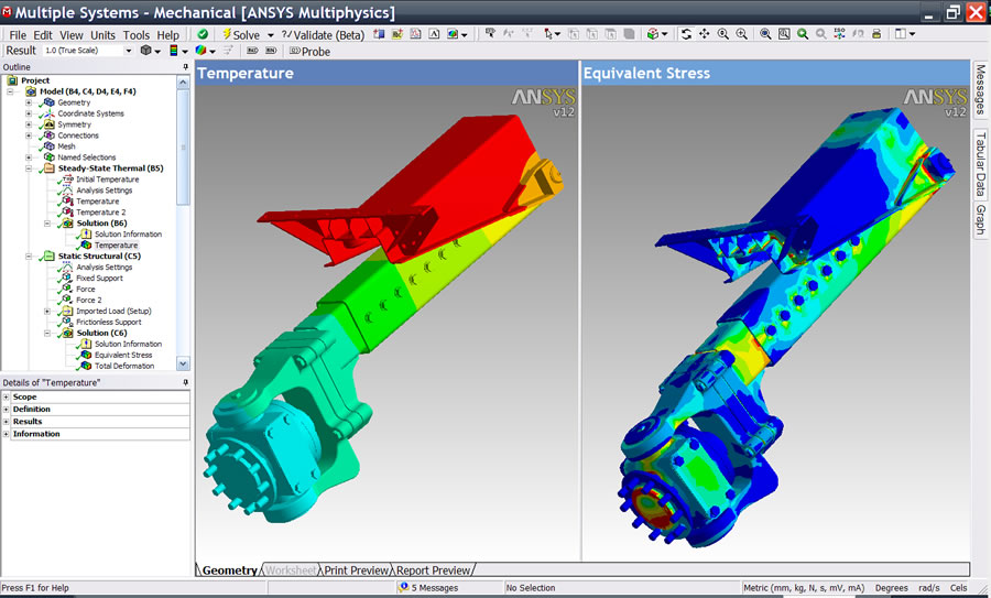
A new trend report on FEA by Global Industry Analysis, Inc. titled “Finite Element Analysis Software” indicates that the growing complexity of today’s products is further driving demand for FEA tools. Engineers and product designers and increasingly using CAD-integrated simulation tools to conduct virtual testing on products throughout the development process to verify real-world performance and optimize designs long before they exist in physical form. This also reduces the need for building physical prototypes, cutting design costs and speeding time to market.

The emergence of cloud and mobile-based FEA software represents a major development in the market, as it enables programmers to access the software and collaborate on results with anyone and from anywhere across the world.

Growing acceptance of Virtual Product Development (VPD) strategies in a wide range of industry verticals offers a strong platform for growth in the market. Emerging countries such as Brazil, China, India, and Korea with their expanding manufacturing base and adoption of virtual product design, simulation, staging, and digital manufacturing practices, are forecast to emerge as lucrative markets for growth in the coming years.

The trend report provides cursory insights into the market, technology, R&D and corporate initiatives of companies worldwide. Companies covered in the report include Ansys Inc., Autodesk Inc., Collier Research Corporation, Cranes Software International Ltd., Dassault Systemes SA, Fedem Technology AS, Intuition Software, NEi Software Inc., PDE Solutions Inc., Rockfield Software Ltd., and Vieux Inc., among others.

The report provides a review of market prospects working process, classification, benefits, drawbacks, and applications of FEA along with several strategic industry activities of major companies worldwide. The report also discusses XFEM, an advanced version of FEM, the major applications of FEA in key end-use segments, including automotive and aerospace, healthcare, and architectural design.

For more details on this report, click here.
Barb Schmitz

Filed Under: News Tagged With: ANSYS, Autodesk, Dassault, FEA, FEM, NEi

SolidWorks 2014: No obvious surprises

January 28, 2013 By Evan Yares 5 Comments

Bernard Charles, explaining where SolidWorks fits in.

There was a time, years back, when SolidWorks users complained because the annual updates of the software included so many major new capabilities that it was hard to keep up.

SolidWorks is a mature product now, and the pace of adding major new capabilities has slowed down quite a bit.

Now the big emphases with new SolidWorks releases are performance, stability, and quality. New capabilities are slanted towards making making existing users happy, and seem, at least to me, to have the common characteristic that they can be added without creating stability problems or regressions. SolidWorks 2013, for example, had a fairly good number of enhancements, but few, if any, of them appeared to be the type of things that that would have required making deep changes to the core of the software.

SolidWorks 2014, due to ship later this year, is likely to continue the trend, with a variety of relatively small enhancements, designed to please existing users. The new version was previewed at SolidWorks World last week. Rather than listing the new features here, I recommend checking out Ricky Jordan’s Blog, where he did a nice job of covering them.

Still, there is one new feature that I find quite interesting: the style spline. SolidWorks splines are not particularly well suited to creating class-A surfaces. Whether it was intentional, or a mistake made long ago, it’s been a problem for users who need high quality surface continuity. I’ve wondered how this could be fixed—my guess was that if the SolidWorks programmers changed the behavior of splines to fix their continuity, they’d introduce incompatibilities with older parts files. It looks like their answer was a good one: introduce a new class of spline specifically designed to give better control and smoothness.

It’s probably risky to predict anything about SolidWorks 2014, since it’s not due to ship for quite a while. But my completely subjective impression is that this may be another good release.

Speaking of future releases: I continue to dig to find information on future plans for SolidWorks. You may know that there’s been uncertainty and concerns among some users about whether Dassault Systemes might eventually “retire” the current SolidWorks generation. Here’s my reading: It’s not going to happen for a very long time.

I figure DS is about as likely to retire SolidWorks as Autodesk is to retire AutoCAD. Neither company is run by people who are dumb enough to kill off products that make them hundreds of millions of dollars a year.


Update: Vajrang Parvate, Director of SolidWorks Product Development, recently made this comment on the SolidWorks forum:

“We invested several man-years in changing some of the core components of the SolidWorks source code in SW2013 – the compiler, the VBA engine that drives macros and equations, the .NET version we run on, support for Windows 8… to name just a few. This was done across the product line – Core SolidWorks, Simulation, eDrawings, Routing, CircuitWorks, etc. and we are continuing to do those kind of long-term investments in the SolidWorks source code. SW2014 development is going on right now and our Product Definition and Product Management teams have begun initial planning for SW2015.

“I hope this says something about the longevity and the future of the products from SolidWorks you know and use today. Bottom line: They are not going away.”

It’s a nice reassurance that SolidWorks is going to be around for a long time. But, it begs a question: Doesn’t this kind of investment qualify as “making deep changes to the core of the software?”

No.  This work was certainly tedious and time consuming, but not “difficult,” in the sense that making major functional changes to SolidWorks would have been. It it was likely necessary to insure compatibility with the new versions of Microsoft’s development tools.

It’s hard to give SolidWorks major brownie points for doing something that every software developer who wants to support Windows 8 has to do.

Had Vajrang said that they’d invested the time and effort to add support for DirectX (as an alternative to OpenGL), I would have been impressed.


Filed Under: Evan Yares, Featured, SolidWorks, SolidWorks News & Events Tagged With: Dassault, SolidWorks

Ice Dream: Towing an iceberg for fresh water

January 10, 2012 By Laura Carrabine Leave a Comment

“With the world’s water resources projected to diminish by one third in the next two decades, providing pure water to an ever- increasing world population is vital,” Mougin explained. To Mougin and Mauviel, one solution would be to transport icebergs to areas that lack fresh water for drinking and even cooling purposes. The scientific challenges are impressive — capturing a large iceberg that can weigh up to 7 million tons, protecting it from melting while transporting it across the ocean, securing and optimizing the trajectory with respect to meteorological and oceanographic conditions, and breaking up the iceberg to turn it into drinking water.

Dassault Systèmes worked with Mougin and his team to simulate the iceberg’s trajectory and its evolution by taking into account data such as variations in ocean temperatures, wind force and direction, sea currents, and boat drag force. They inserted this data into a 3D model of the iceberg to simulate what would happen all along the voyage.

The critical challenge presented to Dassault Systèmes’ engineers was to demonstrate, using virtual technology, the technical feasibility of displacing the iceberg in a controlled manner while reducing its melting. The project, managed by Cédric Simard, Interactive Strategy & Marketing Project Director at Dassault Systèmes, involved a number of steps:

  1. Model the iceberg with CATIA based on a cloud of points obtained by scanning a real iceberg with radar.
  2. Calculate and simulate the way the iceberg would melt using CATIA Systems and SIMULIA.
  3. Simulate the way the iceberg would melt if surrounded by a protective isothermal “skirt” imagined by Mougin to slow the melting process.
  4. Calculate how much fuel the boats would consume depending on the winds and currents encountered along the way

Various scenarios were simulated, such as number of boats needed, different departure dates and climate conditions, and the behavior of the boats and iceberg in the event of a storm or turbulence. In addition to enabling the team to visualize these scenarios, the simulation also allowed the scientists to test how to deploy the isothermal skirt around the iceberg.

Dassault Systemes

www.3ds.com

Filed Under: Catia, Catia Blogs, Featured, PTC News, Simulation Software Tagged With: Catia, Dassault, Simulia

Recreated USS Missouri

December 13, 2011 By Laura Carrabine Leave a Comment

SolidWorks user Donn McKinney’s dream is to construct a Hollywood-quality fleet of battleships for museums and ports. He is part of a team engaged in producing operational replicas of the Iowa Class Battleships USS Iowa, USS New Jersey, USS Missouri, and USS Wisconsin. The goal of the project is tto put these ships on display for education and enjoyment of the general public in various venues.

“Battleships like the Missouri bring waves of emotion to people. Seeing tese floating parts of history conjures memories of sadness, joy, and wonder, “ said McKinney. “My goal is to bring living history to those people and cities who feel connected to these now almost mythical ships.”

Through advancements in SolidWorks software, McKinney has seen his project evolve from an 18-ft wooden ship, to an 18-ft steel ship. More recently, the latest rendition of the project is a 28-ft replica that features the ship’s complete functionality including radar and fully operational scaled weapons. McKinney is also adding a system that will allow presenters to give full military orders to the vessel and receive an immediate response.

“When these ships were first built, they were termed as “the most complicated moving man-made objects on Earth. Indeed, they were and continue to stand as great feats of engineering, said McKinney. “Thanks to SolidWorks, I am creating complex ships with ease and ensuring the replicas are truly authentic by using the state-of-the-art technology.”

He is adamant that any ship can be created using this methodology including the USS Arizona, the French Battleship Richlieu, and the British Battleship HMS Hood among others.

SolidWorks

www.solidworks.com

Filed Under: 3D CAD Package Tips, SolidWorks, SolidWorks Blogs, SolidWorks News & Events Tagged With: 3D CAD, Dassault, SolidWorks, USS Missouri

Sea monster of a yacht

September 21, 2011 By Laura Carrabine Leave a Comment

The Volvo Ocean Race for 2011-2012 includes 70-ft Mar Mosto, the “Monster of the Sea” entry. Designed by Juan Yacht Design of Valencia, Spain and constructed at New England Boatworks in Portsmouth, RI, the mono-hull was created to sail around the world and face extreme conditions.

The yacht weighs approximately 15 tons and will reach speeds up to 40.5 knots (46.6 mph) during the race. According to designer Juan Kouyoumdjian, the design process was divided into two sections: research and development and manufacturing. His team used Catia software as the basis of the 3D modeling, Hyperworks for the structural analysis, and Star CCM for all the CFD work such as hydrodynamics, aerodynamics, and structures.

For the 2011-2012 race, Puma Ocean Racing partnered with Berg Propulsion, a leading designer and producer of controllable pitch propellers for commercial shipping. During the nine months of the Volvo Ocean Race which starts in Alicante, Spain in November 2011 and concludes in Galway, Ireland in July 2012, the teams will sail more than 39,000 nautical miles.

Other interesting facts about Mar Mosto

Mast height: 105 ft
Boom length: 28.5 ft
Total sail area: 2,215 sq ft
Mainsail area: 1,884 sq ft
Spinnaker area: 5,384 sq ft
Boat material: carbon fiber
Sail material: Aramid/Spectra Blend
Build hours: 39,536
Paint hours: 600

Puma Ocean Racing
www.pumaoceanracing.com

Dassault Systemes
www.3ds.com

Altair
www.altair.com

CD-Adapco
www.cd-adapco.com

Filed Under: 3D CAD Package Tips, CAD Package, Catia, Catia News & Events, Simulation Software Tagged With: Altair, Catia, CD-Adapco, Dassault, Hyperworks, Juan Yacht Design, New England Boatworks, Puma, Star CCM 3C CAD, Volvo

20th release of SolidWorks wins kudos

September 7, 2011 By Laura Carrabine Leave a Comment

There are new drawing tools to help create better looking and more accurate images. For example, changed dimensions are automatically highlighted and show previous values to help with revisions. Sequential balloon ordering and magnetic lines automatically help order and position balloons. So you may not have to spend as much time detailing and aligning drawings.

SolidWorks’ Sustainability’s new user interface can be used to more accurately model products with “what-if” scenarios and custom materials. Users can model processes with parameters such as recycled content and duration of use. Access to the latest Sustainability supplemental materials will be instant and continuous as they become available.

The large design review allows instant opening and review of large assemblies or any individual component with walkthroughs, sectioning, and measuring without the need for a high-powered computer or special file preparation. The freeze feature eliminates unwanted feature rebuilds by locking all features above the “freeze” bar. This option can help speed up the design of complex models where rebuilding specific features is not needed. Features can also be unfrozen at any time. There are also new equation capabilities that speed up the calculation process.

Design costing is a tool that automates manufacturing cost calculations for sheet metal and machined parts. Designers can make more informed decisions based on cost throughout the design process and continually model new scenarios for instant up-to-the-minute manufacturing estimates. SolidWorks 2012 offers new sheet metal tools such as precise control of edge flanges, including up-to-vertex end conditions. Designs can be flattened and documented for manufacturing with export to CNC and manufacturing equipment.

SolidWorks Simulation includes enhanced motion optimization that automatically uses motion study results to create sensors and refine complex and time-intensive machine aspects such as motor size, bearing loads, and range of travel. Users can optimize designs quickly as they refine inputs and immediately see changes to restraints or goals.

SolidWorks Enterprise PDM has new support for Office 2010 and an x64 web client. In addition, there are enhancements to 3DVIA Composer including part-to-part shadows, ambient occlusion, and shadows to 2D panels with precise control. A glow effect can also be added to highlight specific areas of interest.

SolidWorks

www.solidworks.com

Filed Under: 3D CAD Package Tips, CAD Blogs, CAD Package, SolidWorks, SolidWorks Blogs, SolidWorks News & Events Tagged With: 3D CAD, 3DVIA Composer, CNC, Dassault, drawings, PDM, sheet metal, SolidWorks

Fly record speeds in the v-44 Albatross

August 31, 2011 By Laura Carrabine Leave a Comment

When Verney Yacht founder Tim Clarke read about the record-setting preparations by the hydrofoil-design trimaran, I’Hydroptere, he knew a technological breakthrough was the key to winning the challenge. He decided to design his own racer. He started to create a single-hull and equip it with two rigid wing-sails. The wing sail has the ability to switch both position and function as the boat tacks becoming either a wing if horizontal to the water or a sail if vertical.

Named the v-44 Albatross, this new concept boat promises 65 knots or greater – 20% faster than the current record. To help translate the conceptual design into a physical reality, Verney’s team used Abaqus FEA software from Simulia, Dassault’s brand for realistic simulation.

Using the software, the team is able to test the boat’s performance virtually. The geometry is created in 3D to analyze the structural strength of components, their response to wind loads, and the craft’s aerodynamic characteristics. Each of the 13-meter long wing sails are comprised of two planks (inner and outer) which are able to freely align to the airflow, like a weathervane. The plank’s structure is intended to mimic the behavior of a tubular spar centered at the axis of rotation, which will have no tendency to rotate under the influence of bending loads. This requirement is essential to preserve the close coupled aerodynamic balance of the wing sails.

For this reason, a different structural approach needed to be taken. Because the wing sail design is unproven in the field, the role of FEA for virtual design and analysis is critical in the success of the project. With the use of Abaqus, Clarke and his team were able to consider many wing sail design variables when moving from the conceptual to preliminary design. Early in the design cycle, the team created some of the key models within Abaqus first and used the extensive functionality within the software’s interaction module to simplify those models. The team also used SolidWorks Premium for additional 3D modeling and product data management. With the complex wing sail structure and function, the team split the analysis into three stages. Each analysis validated the wing sail concept and indicated several design issues. When the design is complete, the v-44 Albatross will be constructed without extensive wind tunnel/tow-tank testing. So the team must ensure they get it right the on the first try.

The Verney team hopes their boat will cover the official 500-meter distance in a scant 16 seconds or less. When it does, the v-44 Albatross will fly above the water with only the keel and rudder breaking the surface.

Verney Yachts

www.verneyyachts.com

Dassault Systemes

www.3ds.com

Filed Under: 3D CAD Package Tips, CAD Industry News, CAD Package, SolidWorks, SolidWorks News & Events Tagged With: 3D CAD 2013 Summer Olympics, Abaqus, Dassault, FEA, simulationh, Simulia, SolidWorks, Verney Yachts

SolidWorks announces winners of Green Design contest

August 24, 2011 By Laura Carrabine Leave a Comment

SolidWorks officially announces its first grand prize winners and runners up of the Green Chair Design. The contest kicked off on April 22, 2011. Contestants used SolidWorks 3D CAD software to design a low-impact airport terminal chair. Other rules: the designs had to be tested with SolidWorks SustainabilityXpress. The contestants were asked to measure the design’s carbon footprint, air and water impacts, and energy consumption throughout the product’s life cycle.

In addition to sustainability tests, every design had to be analyzed with SolidWorks SimulationXpress to ensure that the chair design could withstand the stresses of everyday use.

Commercial grand prize winner was Russell Donovan of New Zealand. His prize? A four-night stay at the Chaa Creek rainforest eco-resort in Belize in recognition for his “leaf” chair design.

Within the education category, the two grand prize winners were Gerald Libby with his “airfoil” chair and Elias Chavez with his bamboo chair reminiscent of a nature lodge. Both won a trip for two to SolidWorks World in San Diego.

A panel of industry and SolidWorks software experts reviewed every design and entry against judging criteria broken up by sustainability, “green” aesthetics, creativity, and manufacturability.

SolidWorks

www.solidworks.com

Filed Under: 3D CAD Package Tips, CAD Blogs, SolidWorks, SolidWorks Blogs, SolidWorks News & Events Tagged With: Dassault, green, SolidWorks, sustainability

3Dconnexion achieves 1,000,000 3D mouse milestone

March 2, 2011 By Laura Carrabine Leave a Comment

3Dconnexion today announced it has shipped more than one million 3D mice, supporting today’s 3D software solutions from companies including Autodesk, Dassault Systèmes,  Siemens, PTC, Google, Microsoft, and Adobe across CAD, digital content creation, architecture and construction, and geographic information systems.

The devices unlock the power of 3D design applications by allowing you to interact naturally with 3D content as if they are holding the model or camera in their hand. Many of the world’s leading companies in industries from aerospace to automotive, consumer goods to electronics, and machine tools to game development, use 3Dconnexion 3D mice to boost productivity, efficiency and the comfort of their design teams.

To mark its “One Millionth 3D Mouse Milestone,” 3Dconnexion will host several activities throughout the next month, offering users the opportunity to win a 3D mouse. For more information, visit 3Dconnexion’s website, Facebook and Twitter.

The core technology inside all of 3Dconnexion’s 3D mice originates from the field of robotics and space exploration. In 1993, a 3D controller was used on the space shuttle Columbia, manipulating the first robotic arm in space, and was the launching point for a family of 3D mice that now help 3D professionals in hundreds of thousands of organizations to design, innovate and create some of the most well known products in the world.

3Dconnexion

www.3dconnexion.com

Filed Under: 3D CAD Package Tips, Autodesk, CAD Blogs, Catia, Inventor, Pro/Engineer, Siemens PLM, SolidWorks Tagged With: 3Dconnexion, Adobe, Autodesk, cad, Dassault, Google, Microsoft, PTC, Siemens

Primary Sidebar

3D CAD NEWSLETTERS

MakePartsFast

Footer

3D CAD World logo

DESIGN WORLD NETWORK

Design World Online
The Robot Report
Coupling Tips
Motion Control Tips
Linear Motion Tips
Bearing Tips

3D CAD WORLD

  • Subscribe to our newsletter
  • Advertise with us
  • Contact us
Follow us on Twitter Add us on Facebook Add us on LinkedIn Add us on Instagram Add us on YouTube

3D CAD World - Copyright © 2022 · WTWH Media LLC and its licensors. All rights reserved.
The material on this site may not be reproduced, distributed, transmitted, cached or otherwise used, except with the prior written permission of WTWH Media.

Privacy Policy