• Skip to primary navigation
  • Skip to main content
  • Skip to primary sidebar
  • Skip to footer

3D CAD World

Over 50,000 3D CAD Tips & Tutorials. 3D CAD News by applications and CAD industry news.

  • 3D CAD Package Tips
    • Alibre
    • Autodesk
    • Catia
    • Creo
    • Inventor
    • Onshape
    • Pro/Engineer
    • Siemens PLM
    • SolidWorks
    • SpaceClaim
  • CAD Hardware
  • CAD Industry News
    • Company News
      • Autodesk News
      • Catia News & Events
      • PTC News
      • Siemens PLM & Events
      • SolidWorks News & Events
      • SpaceClaim News
    • Rapid Prototyping
    • Simulation Software
  • Prototype Parts
  • User Forums
    • MCAD Central
    • 3D CAD Forums
    • Engineering Exchange
  • CAD Resources
    • 3D CAD Models
  • Videos

PDM

3D PDFs Provide Easy Way to Share CAD Data

August 20, 2014 By Barb Schmitz Leave a Comment

Earlier this week in this blog, I discussed how users can maximize their investments in 3D CAD systems by sharing their CAD data with downstream data consumers, such as documentation, assembly, manufacturing, quality, sales and marketing personnel. Sharing technical data with these people can speed up all of the supporting activities that accompany product development and assist with getting products to market successfully.

So the question arises, what is the best way to share technical data with stakeholders outside of engineering? I came across an interesting blog written by Bill Barnes of Lattice Technology that addresses this issue and I found much of it worthy of sharing.

One of the issues with sharing technical data is the fact that many of the intended recipients are non-technical, meaning they don’t use 3D CAD. The types of users involved can also vary widely in terms of the type of devices they would be receiving the data on, such as desktops, laptops or mobile devices, such as phones or tablets.

So now an organization is faced with a long list of use cases, with different type of stakeholders, needing different ways to access. With this in mind, organizations must answer these questions:

* Ease-of-use and accessibility. How do people consume this 3D data, and how difficult is it?
* Cost. How much are the licenses?
* Installation. Can you bring a new application into your current IT environment?

The solution: 3D PDF

Everyone knows about the ubiquitous PDF and how useful it is when sharing documents. In fact, everyone has the Adobe PDF reader. What you may not know is that the standard Adobe PDF Reader (that everyone has) can display interactive 3D data and can contain other related information as well – think of it as a container – more on that later.

What makes 3D PDF an ideal solution is that it is easy to use, free, already is on your computer (and apps are available for tablets), and enables anyone inside or outside of your company to easily access and use your valuable 3D engineering data via their desktop or mobile device–without additional licensing costs.

3D PDF Components

Sharing of your interactive 3D model is only the beginning. The 3D PDF is a container. Adobe designed a tremendous amount of flexibility into this powerful file format. Other data structures that might be included could be any that have a relationship to the CAD assembly model data—for instance:

* Part Lists
* Procedures for completing a task, also known as work instructions or tasks
* Snapshots and animations of the steps of an assembly process or a service procedure

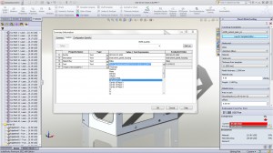
Easily create 3D PDFS to share 3D CAD data, such as part lists, with others, even non-technical people using the Lattice Technologies' solution.
Easily create 3D PDFS to share 3D CAD data, such as part lists, with others, even non-technical people using the Lattice Technologies’ solution.

Using 3D PDF standalone or part of PLM/PDM processes

It doesn’t matter if you are a small engineering company or a Fortune 100 manufacturing company, using 3D PDF for sharing interactive 3D models with related information (including PMI) is probably the best way to share with any stakeholder. If you are a big company, you will most certainly have a PLM or PDM system, and the 3D PDF can easily be tucked in with all the rest of your files. If you are a small company, the 3D PDF can become a mini PDM system using its container capabilities to hold all of the above items as well as the original CAD data format and neutral formats, such as IGES and STEP.

There are many 3D PDF generation solutions on the market today — most simply convert CAD geometry– that’s all. The more robust solutions usually require scripting and programming.

Lattice Technology offers a solution that enables a person without CAD experience and without programming or scripting to easily and quickly create these powerful 3D PDFs with extended information. The solution uses a template approach, which allows users to establish standards for their 3D PDFs.

To read the entire blog, “3D PDF – Squeezing Value from CAD Models by Sharing Technical Data,” click here.

Barb Schmitz

Filed Under: News, PLM/PDM Tagged With: 3D PDF, CAD data, PDM, PLM

The Benefits of Intelligent Part Numbering

July 30, 2014 By Barb Schmitz Leave a Comment

Companies–both large and small–must manage increasingly large amounts of data. Within engineering departments, this might include drawings, part files, and lots of other files that represent products. Keeping track of this data is difficult without some type of file management system in place, however, statistics show that the majority of companies continue to manage their data–often inefficiently–without any type of system in place.

Reasons behind why companies don’t implement document management systems, such as PDM or more enterprise-wide PLM systems, vary. Commonly cost is an issue as well as the complexities around implementing these systems. Often engineering departments don’t have the dedicated IT resources to facilitate such implementations, especially at smaller companies.

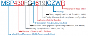
It's important for all companies to evaluate the pros and cons of part numbering schemes.
It’s important for all companies to evaluate the pros and cons of part numbering schemes.

Which part numbering scheme is best?

Part numbering certainly seems like an easy enough task, however, if not done using a consistent methodology, chaos will reign. Turns out nearly every company struggles with defining part numbers.
Without some type of organized system in place, finding the right part files will prove difficult, and time will be wasted. Engineers spend a ridiculous amount of time searching for files, time that could be spent doing actual engineering work.

So the question becomes: should companies mandate use of an intelligent numbering system that embeds important identifying information or go with easy-to-manage generic numbers.

I came across a blog written by Ed Lopategui on the GrabCAD site that seeks to unveil the logic behind a couple of different approaches to part numbering. The author doesn’t seek to crown a winner of this debate, but to help everyone understand the issues and how they will affect your company.

Creation and Data Entry

Generating a new number should be easy, even for the new intern. Nothing is easier than a system-assigned generic number. PDM/PLM systems default to a generic numbering system, but that is neither a recommendation nor a limitation. Most modern systems can accommodate intelligent numbering without heavy customization and/or manual entry. If you choose to embed intelligent information, you are trading the simplicity of creating a part number for a downstream benefit, so weigh that benefit carefully. Consider the part number is often what you start with on new design.

How much will you know at that stage and how certain are you about it? Could that information change in the future? Such considerations will help determine what information, if any, is truly practical to embed in an intelligent number.

Longevity and Legacies

You want your part numbers to last. Intelligent numbering systems tend to break down over time, especially if the intelligence is used for complex categorization. It probably won’t be tomorrow, or next week, but a couple of years from now, someone will likely be staring at a screen and shaking their fist at you because something doesn’t quite fit. The more complicated the system, the higher the likelihood it will break down.

Well-planned systems, however, can last. Before you get too caught up on planning for infinite longevity, keep in mind all of it may come crashing down come a merger or acquisition. Also, don’t forget about the part numbers you already have; you just might be stuck with them.

Readability

Readability is absolutely critical, people need to quickly parse through a large amount of part numbers every day and short-term retention is important. Generic numbering tends to be less readable without some designed structure or variation (i.e. breaking up long series of numbers with letters or dashes at fixed positions). It’s the reason you might remember a telephone number with an area code, but not your license plate, despite a smaller namespace. Intelligent numbers can have readability issues for the very same reasons, or if they just get too long.

Uniqueness

Two parts with the same number is trouble. Some argue that only generic numbers ensure uniqueness, but that’s not really true. You can get the same uniqueness guarantee with the right PDM/PLM system for intelligent numbering. Generic numbers, which tend to be shorter, can actually increase the chance of overlap with respect to mergers and acquisitions or cause confusion with similar supplier part numbers. Nothing ensures uniqueness in this scenario, but the larger the namespace, the lower the chance for a collision. But once again longer part numbers degrade readability.

Interpretation

Every time a part is handled, sorted, searched, or otherwise used an interpretation cost is involved. In other words, it’s the time needed to understand whether you are dealing with the right part. Intelligent part numbers can reduce this interpretation cost, provided the user understands the identification system. In the right conditions, parts can be recognized at a glance. Take caution, however: if the cost of maintaining the intelligent system exceeds the interpretation cost, it’s self-defeating. Generic numbers, on the other hand, can increase interpretation costs, since differences have to be queried in the system. Generic part interpretation can be enhanced with classification systems, but they also add cost.

Balancing all these diverse factors is difficult, because no solution is optimal for every company.

Here are some final tips to help you make prudent decisions:

* Understand your PDM/PLM system part number generation capabilities.
* Understand the limitations of any other systems that interact with your parts.
* Go through every activity that requires interpreting part numbers and understand what system access is available, and how the interfaces work. This will provide a good basis for your interpretation cost.
* Understand how easy/difficult it is for a new employee to interpret a part number

To read the entire blog, click here.

Filed Under: News, PLM/PDM Tagged With: part numbers, PDM

5 Steps to Better CAD File Management

April 23, 2014 By Barb Schmitz Leave a Comment

A problem that plagues most engineering departments is a lack of any type of structured management of CAD files. Individual engineers might deploy what they regard as a very organized way to manage their own files, giving each meaningful file names and storing them on their hard drive. The problems arise, however, when those files must be shared and worked on by other engineers.

As the number of engineers working on any one project increases, managing those files in a directory structure becomes risky. Using a shared drive can result in issues related to managing multiple design iterations. Finding the most current version of a file can be problematic as can be assuring that another engineer isn’t overwriting the changes you’ve just worked hours to make.

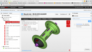
GrabCAD's Workbench is a cloud-based file management solution that is available for users on a monthly basis for $59 (Professional) or $89 (Enterprise).
GrabCAD’s Workbench is a cloud-based file management solution that is available for users on a monthly basis for $59 (Professional) or $89 (Enterprise).

Bring order to chaos

According to several industry surveys and studies, most manufacturers have not implemented any type of organized PDM or PLM system. By continuing to manually manage CAD data, these companies face potentials risks that include lost work, poor productivity, and errors. Common reasons cited for not implementing any type of CAD data management solutions include high cost, too much complexity and a lack of IT resources.

Recognizing the shortcomings and inherent risks associated with manual CAD file management is the first step. The good news is that there are a lot of options available today, including new cloud-based tools. In a newly published Tech-Clarity Insight report, “When Brute Force Fails and PDM is too Much,” the various solutions are explained in detail as well as the basic requirements of a CAD management solution.

Based on industry experience and extensive research, Tech-Clarity makes the following recommendations of organizations looking to improve CAD file management.

5 Steps to better CAD management:

1. Determine your needs. Understand the basics required to control, access, and share your CAD data.

2. Shop around. Evaluate solutions to decide which one is right for your business, based on your organization’s level of process maturity and available IT support.

3. Make it easy to share. This is important as engineers don’t work in a vacuum and must easily share files. Some solutions’ strength is in ease of sharing, while others might focus on a strong control paradigm.

4. Look to the cloud. Consider cloud-based solutions that combine ease of use, less risk, low cost and reduced need for IT resources, but are designed with CAD data management in mind.

5. Get started. In some cases, you might need a more traditional CAD file management solutions, but recognize that putting in place structure of any kind is a step in the right direction and then get going.

To read the entire Tech-Clarity report, download the full report on the Tech-Clarity website.

Barb Schmitz

Filed Under: News, PLM/PDM Tagged With: CAD management, PDM, PLM

20th release of SolidWorks wins kudos

September 7, 2011 By Laura Carrabine Leave a Comment

There are new drawing tools to help create better looking and more accurate images. For example, changed dimensions are automatically highlighted and show previous values to help with revisions. Sequential balloon ordering and magnetic lines automatically help order and position balloons. So you may not have to spend as much time detailing and aligning drawings.

SolidWorks’ Sustainability’s new user interface can be used to more accurately model products with “what-if” scenarios and custom materials. Users can model processes with parameters such as recycled content and duration of use. Access to the latest Sustainability supplemental materials will be instant and continuous as they become available.

The large design review allows instant opening and review of large assemblies or any individual component with walkthroughs, sectioning, and measuring without the need for a high-powered computer or special file preparation. The freeze feature eliminates unwanted feature rebuilds by locking all features above the “freeze” bar. This option can help speed up the design of complex models where rebuilding specific features is not needed. Features can also be unfrozen at any time. There are also new equation capabilities that speed up the calculation process.

Design costing is a tool that automates manufacturing cost calculations for sheet metal and machined parts. Designers can make more informed decisions based on cost throughout the design process and continually model new scenarios for instant up-to-the-minute manufacturing estimates. SolidWorks 2012 offers new sheet metal tools such as precise control of edge flanges, including up-to-vertex end conditions. Designs can be flattened and documented for manufacturing with export to CNC and manufacturing equipment.

SolidWorks Simulation includes enhanced motion optimization that automatically uses motion study results to create sensors and refine complex and time-intensive machine aspects such as motor size, bearing loads, and range of travel. Users can optimize designs quickly as they refine inputs and immediately see changes to restraints or goals.

SolidWorks Enterprise PDM has new support for Office 2010 and an x64 web client. In addition, there are enhancements to 3DVIA Composer including part-to-part shadows, ambient occlusion, and shadows to 2D panels with precise control. A glow effect can also be added to highlight specific areas of interest.

SolidWorks

www.solidworks.com

Filed Under: 3D CAD Package Tips, CAD Blogs, CAD Package, SolidWorks, SolidWorks Blogs, SolidWorks News & Events Tagged With: 3D CAD, 3DVIA Composer, CNC, Dassault, drawings, PDM, sheet metal, SolidWorks

PTC congratulates Penske Racing team for unprecedented weekend of race track wins

August 31, 2011 By Laura Carrabine Leave a Comment

PTC congratulated its customer and performance partner, Penske Racing, whose cars are designed and developed with the help of PTC’s design software, on its banner racing weekend. The Team Penske IZOD IndyCar Series team swept the podium on August 28 as its three drivers claimed 1st, 2nd and 3rd place at the Indy Grand Prix in Sonoma, California and 1st place at the NASCAR Sprint Cup Series Irwin Tools Night Race in Bristol, Tennessee on August 27.  Often referred to as the “New York Yankees of motorsports,” these recent victories add to Penske Racing’s impressive record of over 330 race wins and 23 national championships.

The Penske Racing Team uses PTC’s design and development software in all aspects of race car design, engineering, testing, and manufacturing, which enables Penske Racing and the Penske Technology Group to develop everything from concept to manufacturing within one solution.  In addition, PTC design technology allows the team to design, prototype, and test in a virtual world which enables them to quickly produce parts in the constantly changing competitive racing environment.


PTC

www.ptc.com

Filed Under: 3D CAD Package Tips, Creo, Pro/Engineer, PTC News, PTC/CoCreate Blogs Tagged With: 3D CAD, Creo, NASCAR, PDM, Penske, PTC, Windchill

Primary Sidebar

3D CAD NEWSLETTERS

MakePartsFast

Follow us on Twitter

Tweets by 3DCADWorld

Footer

3D CAD World logo

DESIGN WORLD NETWORK

Design World Online
The Robot Report
Coupling Tips
Motion Control Tips
Linear Motion Tips
Bearing Tips

3D CAD WORLD

  • Subscribe to our newsletter
  • Advertise with us
  • Contact us
Follow us on Twitter Add us on Facebook Add us on LinkedIn Add us on Instagram Add us on YouTube

3D CAD World - Copyright © 2021 · WTWH Media LLC and its licensors. All rights reserved.
The material on this site may not be reproduced, distributed, transmitted, cached or otherwise used, except with the prior written permission of WTWH Media.

Privacy Policy