• Skip to primary navigation
  • Skip to main content
  • Skip to primary sidebar
  • Skip to footer

3D CAD World

Over 50,000 3D CAD Tips & Tutorials. 3D CAD News by applications and CAD industry news.

  • 3D CAD Package Tips
    • Alibre
    • Autodesk
    • Catia
    • Creo
    • Inventor
    • Onshape
    • Pro/Engineer
    • Siemens PLM
    • SolidWorks
    • SpaceClaim
  • CAD Hardware
  • CAD Industry News
    • Company News
      • Autodesk News
      • Catia News & Events
      • PTC News
      • Siemens PLM & Events
      • SolidWorks News & Events
      • SpaceClaim News
    • Rapid Prototyping
    • Simulation Software
  • Prototype Parts
  • User Forums
    • MCAD Central
    • 3D CAD Forums
    • Engineering Exchange
  • CAD Resources
    • 3D CAD Models
  • Videos

CAD Blogs

Reuse CAD data for technical documentation, split function and feature recognition

February 15, 2019 By Leslie Langnau Leave a Comment

KISTERS North America released version 2019 of its 3DViewStation product family. The new version features additions and enhancements that assist users in the area of repurposing their CAD data. For instance: V2019’s new technical documentation features include the splitting function, real-time wall thickness measurement, feature recognition and a user-friendly import dialog.

One challenging area in the reuse of CAD data lies in the creation of content for technical documentation purposes. Deliverables might be images, illustrations or interactive 3D geometry to be repurposed in printed manuals, online manuals or spare part catalogues.
“After reviewing our customer’s most important requirements for technical documentation processes, we created interactive and automatic BOM ID generation,” said Robert Collins, KISTERS North American Sales Manager.

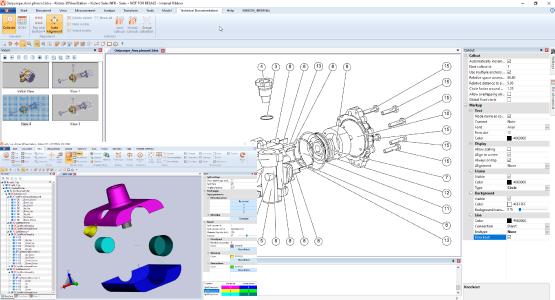
“These BOM IDs will be reused to interactively and automatically generate balloon callouts in an exploded view of the assembly. In our new version, there are multiple new options to configure the arrangement of these balloons. For example: top and bottom, left and right, or in a rectangle. For further ease-of-use, we added the option to continuously recalculate the best possible layout, while rotating the 3D model.

“Another focus was to increase the value of 3DViewStation for our mold/die and casting customers. The splitting function complements our existing draft angle analysis tool,” he added. “Now you can easily determine the complexity of a tool, what will be required to produce a part and extract the face for the mold. Toolmakers will fine the feature recognition functions, such as the drill hole recognition tool, useful. Less experienced CAD users will have the new, easy-to-use import dialog. And all users will experience 3DViewStation rendering significantly faster once more.”

3DViewStation ships with current and mature importers for a range of 3D and 2D formats including Catia, NX, Creo, SolidWorks, SolidEdge, Inventor, JT, 3D-PDF, STEP, DWG, DXF, DWF, MS Office and more.

V2019 Upgrades Include:

– New and updated file formats:
– Import 3D: Inventor 2019, SolidWorks 2019, Solid Edge 2019, Parasolid V31, Revit 2019, FBX, glTF, JT 10.2, OBJ
– Import 2D: Catia V5 R28 (V5-6R2018), Catia V6 R2017x, Creo 4.0 / ProE, NX12, SolidEdge ST10, Solidworks 2018
– Export: JavaScript for 3D-PDF, IFC, FBX, JT 10, OBJ
– New and updated functions:
– Import dialog (quick settings)
– Structure tree: Remove empty nodes
– Neutral axis calculation with tesselated data
– Real-time wall thickness measurement
– Drill hole recognition
– Split
– Technical documentation:
BOM table: interactive BOM ID generation
BOM table: automatic ID generation
Ballooning: arrangement as line, rectangle, circle
Ballooning: automatic re-arrangement during rotation
Options for shapes and lines for balloons
Replace existing SMG files by 3DVS counterparts, limited to supported objects & properties
– Printdialog:
Print range
Autorotate document
Tiled printing
– Selection of all instances of a geometry
– Filtering option: include / exclude unvisible objects
– Rotation mode “Turntable”
– 2D text search enhanced
-Transformation: Align move circle center to circle center
– Export PNG with transparent background
– PDF template: configurable date
– New options for license borrowing
– Performance optimization:
Tremendous increase in rendering speed of ultra large assemblies
Calculation of Level of Detail (LoD)
Ability to remove normals (space-saving)
Optimization of instancing

KISTERS AG
www.3dviewstation.com
Filed Under: CAD Package, News Tagged With: kisters

“3D Evolution Simplifier” simplifies the handling of large CAD data models

October 3, 2018 By Leslie Langnau Leave a Comment

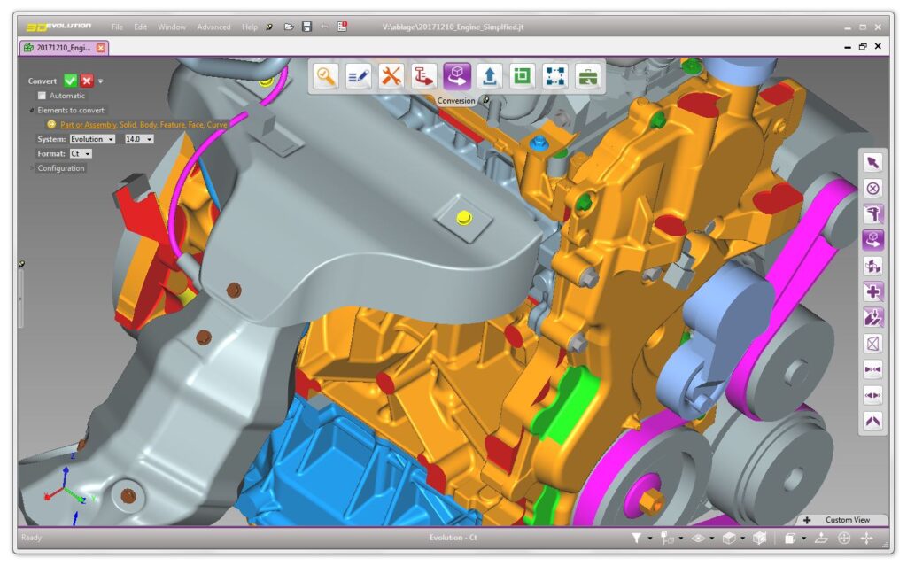
The “3D_Evolution Simplifier” of the German-French software manufacturer CoreTechnologie is software for the fast and fully automatic simplification of CAD data. The tool converts and handles the reading and writing of all popular formats such as Catia V5 and V6, NX, Solidworks, Creo, Inventor, Step, IGES, JT, XT, FBX, DWG and DGN. In addition to conversion and simplification, the models can be checked and optimized in terms of quality.

Envelope geometry improves CAD performance
With the increasing level of detail and the size of CAD models, the number of entities to be displayed is in most cases beyond the capabilities of today’s CAD workstations. Automated simplification and data reduction is essential for the control of large volumes of data to create layouts or VR models in the field. The fast and fully automated generation of envelope geometries is a viable solution to smoothly work with the large amounts of data, especially in plant construction.

Preparation of customer or supplier data
The Simplifier simplifies and converts supplier data. The removal of internal geometry for the calculation of envelope geometries can be achieved within seconds by pressing a button. For efficient reduction of the file size, solids are produced automatically without any inner workings. The “Healing” technology ensures the automatic analysis and repair of the 3D models. The automatic correction functions improve data quality to optimize data exchange, especially for imported data.

The result of the simplifier process and quality optimization is higher performance in the CAD system and in all downstream processes. Particularly suitable is the method for Digital Mock Ups. In addition, problems in the drawing derivation are eliminated by the significantly reduced amount of data and the high data quality.

Automated product release with know-how protection
The model simplification is automated in batch mode and can be performed for any number of files and directories. Attributes in the CAD data, colors and names of the components allow precise control of the simplification process. Thus, certain components are specifically excluded from the simplification, completely removed or replaced by highly simplified, that is approximate envelope contours.

The envelope contours provide the replacement of the original geometry for an additional reduction in file size. Sheet metal parts can be replaced, for example, by boxes, threads or gears by cylinders or more complex geometries with cooling fins by polyhedra. In addition, Enterprise Datamanager offers various automation options. Web-based client / server solutions, multiprocessor operation, command-line operation and the optional directory scanner provide seamless integration into existing PLM environments as needed. The directory scanner monitors defined folders and processes data stored in them.

Another option for integration into existing PLM systems is the command line. The integration enables automation for the provision of product data, for example for catalog systems such as Docware or Engineer-to-Order systems such as Siemens PLM Rulestream.

Preparation of CAD data for VR / AR
When processing CAD data for visualization in virtual or augmented reality, the 3D_Evolution Simplifier is used to reduce the number of polygons without quality disadvantages, i.e. by 90% or more, in typical models from the mechanical and plant engineering sector. The process is based on removing the internal geometry and drilling based on optimized B-rep solids. After reading the original CAD geometry, the simplification of the exact B-Rep data takes place. Subsequently, the conversion to formats such as obj and fbx with definition of the polygon size as well as the reduction of the tessellation by up to 98% is accomplished. Since Simplifier simplifies simplified B-Rep geometry with topology, no holes or unwanted geometry deformations occur.

CoreTechnologie
www.coretechnologie.de/produkte/3d-evolution

Filed Under: CAD Package, News Tagged With: coretechnologie

6 ways Onshape helps you dump your Laptop!

January 30, 2018 By Leslie Langnau Leave a Comment

Phil Foley, guest blogger

1.   You no longer have to travel with a laptop

Engineers, designers and other users of Solidworks, Inventor, Creo and Rhino, it’s time to dump your laptops. Onshape is the first web-based 3D Computer-aided-design package.
Can a web-based package handle or even compete with your custom built, rock solid Workstation? Yes.

For the short time I’ve been using Onshape I have seen several updates and new videos added to their site. The site also boasts a Learning Center that offers self-paced learning videos that I found to be very good. You can also obtain Instructor led training videos that range from $150, $250 to $500 USD. Their free video offerings will get you up to speed.

Solidworks and Inventor users will feel at home with this product due to its similar workflow and terminology. The learning curve is not steep at all. I was up and running in an hour, and after two weeks I was teaching students how to design using Onshape.

2.   Free and easy signup

I went to Onshape and it was a simple free signup. They offer Student, Teacher and Hobbyist accounts that are free. The only catch here is that your files are part of their Public library. For professional users, Onshape offers only a flat $125 per month, paid annually, which equates to $1,500 per year in a single payment.

The six founders of Onshape helped build Solidworks into a world leader in 3D design software. So, Solidworks users will feel a similar work flow. You can find info on the founders here.

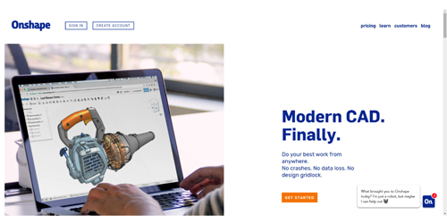
The image in Figure 1 shows the login screen.

You will be happy with the intuitive User Interface mixed with CSS stylings and talented java scripting.

3.   The interface is smooth and quick

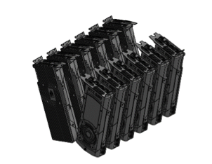
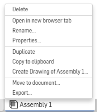
I surfed in the Public folder for a file that looked interesting and found a Nvidia Geforce GTX-980 Ti Video Card designed and uploaded by Zoran Simeonov. I could not find any meta data on the file so I decided to test the Export functions. I exported this file by Right Clicking (RC) on the Assembly tab located at the bottom of your screen and then selecting Export in the options menu as shown in Figure 4.

Figure 2-Nvidia GTX 980
Figure 3- Nvidia GTX 980

Exporting to Solidworks format creates a 13 Mb file, exporting to an STL file created a smaller 6.18 Mb file and Rhino created a whopping 38.32 Mb file size. Just for fun I imported the files into Rhino and they came in clean and with no noticeable data loss.

I wanted to add some stress to Onshape to see what it could handle so I created an assembly file and added 12 GTX Video Cards. Based on the file sizes I mentioned, a Solidworks assembly file with 12 video cards would be in the neighborhood of 163 Mb, STL roughly 74.16 Mb and Rhino bloating out at around 459.6 Mb. I closed the assembly and reopened it. It took a long 15+ seconds to open, however, it seemed to do all the heavy lifting upon opening.

After the assembly file loaded I was able to rotate it as if it was a single Socket Cap Screw. By Right Clicking and holding, I was able to rotate the entire assembly without any video pixilation, video drag or delay; it was smooth.

Figure 4- RC on the Assembly Tab
Figure 5- Export Options

4.   Sheet Metal Modeling is intuitive, quick, and fun to use

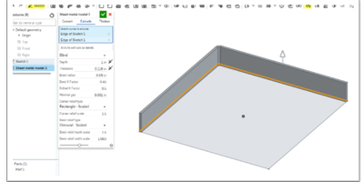
Sheet Metal Modeling in Onshape couldn’t be easier.   I sketched a quick Center Point Rectangle, clicked OK, then selected the Sheet Medal Model button. The following image shows the 2D sketch on the top plane with two edges selected. The two selected edges are new Sheet Metal flanges.

Figure 6- Sheet Metal Tool Bar


Figure 7 – Two edges selected to create the first Sheet Metal Flanges

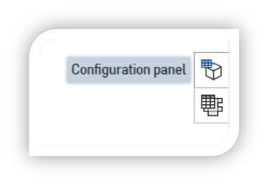
The real power of the Sheet Metal Modeling comes when you want to look at multiple views. Selecting the Sheet Metal mode, two new Icons appear.

Figure 8 – Two new Tabs appear when you enter Sheet Metal Model mode

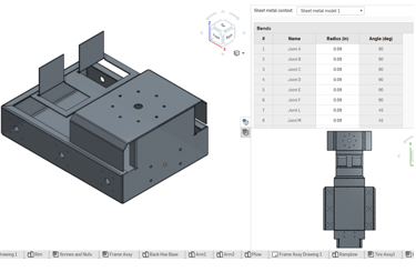
The Tab and Flat View bring up a LIVE 3 view display (Fig. 10)

Figure 10- Sheet Metal Table and Flat View

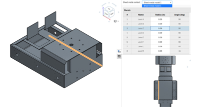
The image in Figure 10 shows the multi view layout. You can interact or modify any view. Let’s assume for a moment that I wanted to change the Bend Radius of Joints A through D. When bent, these four bends represent the base of this chassis. I have typically gone back into the 3D model to make this edit. I know Solidworks and other Parametric Modelers also show bend tables, and they can be edited. I do however, feel this visual interface allows for rapid edits and updates. Looking at Figure 10, notice when I select Joint C in the Bend Radius Table, the actual bend is highlighted in all three views as well.

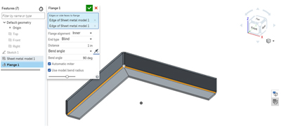
One of my favorite features in Sheet Metal modeling is the Automatic Mitering. You can toggle this feature on/off by selecting or deselecting the checkbox Automatic Miter box. See Figure 9.

Figure 9 – Adding Flanges and Automatic Miters


Figure 11- Live Editing with Bend Radius Table

5.   Creating Drawings with all associated data at your fingertips

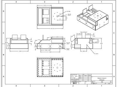
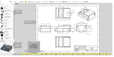
I was pleased when I started to add drawings. The typical dimensioning tools were available including the ability to add your BOM, Insert a DXF/DWG or Image files too. The presentation of information was done well. As you can see in Figure 13, I had more than ten files open. My entire design was displayed nicely using Tabs located across the bottom of my screen. My entire design was at my fingertips.

Figure 12- Onshape offers a robust set of Drawing tools


Figure 13- Highlights of all the information at your fingertips

The Feature Tree showed all parts, assemblies and drawings associated with my design. I was dimensioning the Sheet Metal Frame and located just below the feature tree was a nice rendered view of my chassis. In, all, the amount of information I found at my fingertips was surprising and efficient. I quickly forgot I was using a web based Parametric Modeler, as it had the feel of any 3D package I’ve used during my career.

Onshape felt powerful during part modeling, even though as the assemblies grew I noticed a slight delay of roughly 9-14 second. However, it was clear they spent a lot of design cycles to handle the video buffering up front, hence, the user experience and workflow didn’t suffer. Drawings also offered a slim list of Export options. You have the choice to export out to PDF, DXF, DWG and DWT. I would like to see them add an option that allows users to select multiple formats for export out at one time.   You will find the typical line weight options, hidden lines, centerlines and a host of other standard CAD features within Onshape’s Drawing module.

Figure 14 – Drawing Export Options

6.   Inserting new elements

My final exploration into Onshape was using the Inserting New Elements option.

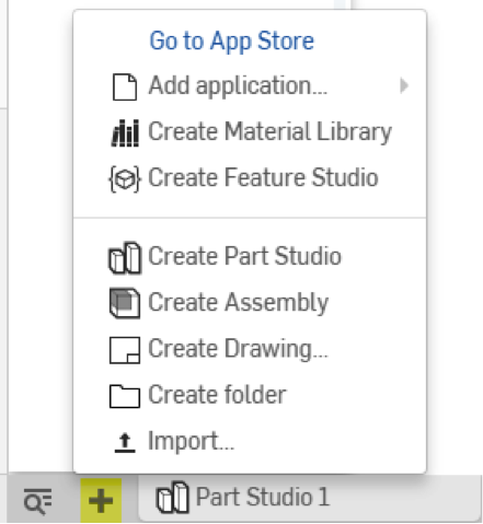
By selecting the Plus sign located at the bottom of the screen you will see the menu shown in figure 15. Select the Go to App Store and browse around for some goodies. They had apps for rendering, simulation, manufacturing, data management, CAM, utilities and import and export apps too. There is a large selection of free apps so I decided to download Power Surfacing, One Render, 3DX Certified Models and Onshape Explode Sample Utility.

Figure 15 – insert New Elements Dialog Box

In testing the One Reader app, I found the integration was seamless, the user Interface was simple to navigate, and I was happy to see the app didn’t come along with annoying advertising billboards. The rendering tools let me create my own materials, lights, and cameras. This app also had the option to create video. Throughout my career I’ve been called upon to create assets for Sales and Marketing so I was happy to see a full set of tools in a free app.

My experience learning Onshape has been positive and I hope this quick introduction ignites your curiosity. I see this product as a game changer or a market disrupter that will challenge the pragmatic design and require all major 3D software companies to roll out their own web-based product.

Only time will tell.

Filed Under: CAD Blogs, Onshape

Is SolidWorks CAM Better Than an Integrated System?

December 15, 2017 By Leslie Langnau Leave a Comment

When the engineering software vendor announced it was moving from integrated CAM to a total CAD/CAM solution industry watchers took note.

Jean Thilmany, Contributing Editor

For engineers and design companies, it’s not difficult to find integrated computer-aided design and computer-aided manufacturing technologies. Yet, the announcement of SolidWorks CAM, released in October as a SolidWorks 2018 add-on, has created a small buzz in engineering technology circles.

Why?

It’s no secret that engineers struggle to create designs that are easy to manufacture while machinists complain about receiving unworkable CAD models.

An imperfect fit

CAM software uses the CAD models to generate the toolpaths that drive computer numerically controlled manufacturing machines. Engineers and designers who use CAM can evaluate designs earlier in the design process to ensure they can be manufactured, thus avoiding product costs and delays.

Without CAM, manufacturers can be on their own when programming machines to make the CAD model. And not all those who design in CAD enter design features into CAM to control the machine tools. Without CAM, manufacturers use the CAD design to program the tools themselves.

SolidWorks CAM could create codes for the end machine used for manufacturing.

“The general idea has been that engineers design something and then the manufacturing people eventually figure out how to manufacture it,” says Sandesh Joshi. “With integrated CAM, they’re not as disconnected as that, but there’s still a disconnect. This SolidWorks tool could close that disconnect.”

Closing the CAD/CAM disconnect

Joshi is chief executive officer at the CAD outsourcing firm Indovance. Previously, he spent six years on the SolidWorks research and development team.

The SolidWorks offering could ramp up the number of CAM users by making the tool available to more engineers and designers, Joshi says. The SolidWorks 2018 release marks the first time that SolidWorks is providing the CAM product as part of its design solution.

SolidWorks CAM is “powered by” CAMWorks, in the vendor’s parlance. Before the October release, CAMWorks, from HCL Technologies, was one of many third-party CAM tools available for integration with the vendor’s CAD program.

Of course other CAD vendors offer integrated CAD and CAM solutions.

Siemens PLM Software, for example, also offers CAMWorks as an embedded solution within its Solid Edge CAD program. NX CAM, also from Siemens PLM Software, is integrated with other NX solutions, which allows NC programmers and manufacturing engineers to associatively access design, assembly and drafting tools in a one part-manufacturing environment, according to that software maker. And CAM features are integrated into the Fusion 360 design tool from Autodesk.

But rather than taking on two separate software solutions, CAD and CAM can act as one system within SolidWorks CAM, Joshi says. That could make CAM easier and more straightforward to the software’s users.

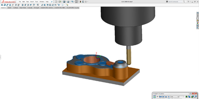
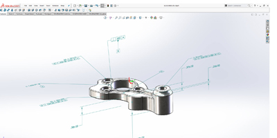
The solution is fully integrated with SolidWorks so users need not leave the familiar SolidWorks environment, says Mike Buchli, senior SolidWorks product and portfolio manager. It supports feature recognition and can generate machining operations directly from native SolidWorks files or from imported data. Toolpaths are automatically updated based on changes to the model.

If SolidWorks 2018 engineers and designers feel they’re working within one integrated system–rather than two separate but connected software systems—they might begin to automatically use CAM and to consistently consider manufacturability as they design the product, he adds.

The vendor’s tool opens the way toward making CAM ubiquitous on engineers’ desktops, much as 3D CAD is now more-or-less used across an industry that once relied on 2D drawings, he said.

The part process from CAD to machining will never be a “one-click process,” Joshi says. But it certainly can become more streamlined through the use of a common CAD and CAM system.

“The difference is engineers would be using CAM as they design so manufacturability is easier,” he says.

“When we build assemblies, we have clash detection. Similarly, CAM gives us red flags for manufacturability right at he design stage, saves a lot of time and money,” Joshi says. “Today all design engineers don’t necessarily deal with CAM, so having access to that will help engineers design for manufacturing way ahead in the product design cycle.

SolidWorks CAM holds the potential for both designers and manufacturers–the possibility of a key to the elusive quest for CNC standardization.

“Some kind of machining cannot be done, and if that’s true it’s better to change the design right away rather than during the manufacturing process,” he says.

The system offers tools to validate and improve part and tool designs, including part-manufacturability checks and tool-motion simulation, Buchli says.

In a blog post introducing the tool, he outlined other benefits, such as the capability to:

–Recognize certain types of geometry to understand how those features will be manufactured, and how much it will cost to manufacture.

–Read tolerances and surface finishes and make decisions about how to manufacture the product

–Automatically apply best manufacturing strategies so manufacturing processes faster and more standard

–Automate quoting and compare it to traditional methods to ensure all aspects of the part are accounted for ahead of time

Fewer codes in the future?

The introduction of SolidWorks CAM holds the potential for another big benefit for both designers and manufacturers: the possibility of a key to the elusive quest for CNC standardization, Joshi says.

If the CAM tool becomes popular among SolidWorks users, Joshi can envision a day when the software automatically produces the G-codes that drive the machines that manufacture the part.

Right now, manufacturers struggle to drive their machining processes directly from their design software. The CAD systems don’t “speak the language” of various machines such as cutters and laser cutters, CNC mills and lathes.

“There are different flavors of G-codes depending on the CNC controller,” Joshi says. “The basic commands and operations generally will work on all machines but there are particular specialties and differences.

If SolidWorks CAM becomes widespread with designers who already use the vendor’s CAD program, the vendor “could potentially create codes for the end machine used for manufacturing,” Joshi adds. “The designer may not have to worry about that up front, but it makes manufacturing a lot smoother.”

With enough popularity, others will adopt those same end-machine codes, he says, creating a more-or-less-standard manufacturing-machine programming code.

And he knows of what he speaks. Currently, designers often rely on machinists and production engineers to develop strategies to effectively make the part.

“Job shops and manufacturing generate G-code for their CNC machine tools based on the CAD models they receive,” Joshi says.

Technologists at his company help interpret “on the back end” how to machine CAD designs, he says. He sees the issues manufacturers have with CAD designs.

“These companies get models from anybody and everybody and they don’t necessarily have all the types of CAD software. So they’re importing raw data rather than inclusive parametric models,” Joshi says. “It still works, but it’s more work.

“If the process is more integrated from end to end, it’s more likely to be seamless,” he adds. “If something has to be changed or modified it can be done quickly rather than going to engineering and coming back and being modified for machining.”

At SolidWorks World 2017, held last February, at which SolidWorks CAM was teased, Buchli related the benefits integrated CAD and CAM can mean for a company, specifically CP-Carillo, of Irvine, Calif., which makes pistons and connecting rods for high-performance race vehicles. The company saw a “significant increase in throughput” when using the then-integrated SolidWorks and CAMWorks, Buchli said in February.

Before using CAMWorks, the manufacturer input SolidWorks model geometry into the Mastercam program to create toolpaths and generate G-codes.

“We programmed each custom piston order manually, slowing down manufacturing,” says Karl Ramm, former CP-Carillo senior technology manager and project developer.

“Each job would take about 10 minutes for non-complex pistons and up to 40 minutes for complex pistons–and that’s programming time alone,” Ramm adds.

When the company brought in the integrated CAD and CAM solution, “custom orders that took days to design and program went down to hours,” Ramm says. “What used to take five to 15 minutes takes seconds now.”

The time-savings comes because the process is automated. Designers load custom criteria into a database and launch SolidWorks. The design application automatically pulls in that criteria and the designer can then create the new piece, which it transfers into CAMWorks. The CAM program then automatically generates new toolpaths and posts them to CNC machines in the shop, Ramm says.

The capability to share that kind of design and programming knowledge between engineering and manufacturing speaks to one of the biggest benefits of an integrated CAD and CAM system, Buchli says.

Another benefit is consistency of workflow. At CP-Carillo, custom orders always follow the same path. Design engineers and manufacturers know what’s expected of them when creating and manufacturing custom orders, Buchli adds.

SolidWorks CAM is much too new to see if any of Joshi’s predictions about standardization and popularity will play out.

But product lifecycle management consultancy CIMdata Inc. says it welcomes the decision to package and offer SolidWorks CAM.

“It protects the investment of CAMWorks users and adds proven CAM capabilities to SolidWorks,” according to a CIMdata statement.

While it remains to be seen if SolidWorks CAM is a step beyond the type of integrated CAD and CAM systems that exist today, Joshi and CIMdata are certain the engineering software vendor has taken a step in the direction down which the industry must travel to iron out disconnects between engineering and manufacturing and to save manufacturers costs and development time in the future.

Dassault Systemes SolidWorks Corporation
Solidworks.com
Filed Under: CAD Package, CAM, Featured Tagged With: dassaultsystemes

Do designers need to get physical?

October 3, 2017 By Leslie Langnau Leave a Comment

As powerful and feature-rich as CAD programs have become, you can argue that there’s a missing element to the design experience. Even augmented reality does not deliver the needed experience, yet.

The experience is actually touching a physical, three-dimensional model of the designed object.

The digital world is working hard to replicate such an experience as best as it can, but nothing quite succeeds like holding the object in your hands and examining and testing it. Simulations are great, and quite mature, but something is still lacking.

/wp-content/uploads/2017/10/18a-SW_2018-Launch-MBD_YOUTUBE-STEREO-v2.mp4


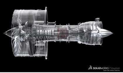
That is one of the reasons behind the trend to offer a fabrication lab experience to CAD designers. Dassault Systemes in Waltham, Mass., recently gave a tour of its new fab lab within the headquarters building. Noted Abhishek Bali, 3DExperience Lab manager, this facility helps CAD software designers, as well as customers, test and play with equipment to learn more about how a design could or should be manufactured and what future features to include in SOLIDWORKS to make the process more efficient. Part of the focus of the new features in SOLIDWORKS 2018 is on shrinking the steps it takes to go from design to actual product production.
/wp-content/uploads/2017/10/4a-SW_2018-Launch-CAM-CNC-Machining_YOUTUBE-STEREO.mp4


This lab has a range of equipment, notably several versions of desktop 3D printers, such as Formlabs and Ultimaker, a Tormach mini CNC mill, a Roland SRM-20 for circuit design and test, a Shopbot CNC router, and even a small robot arm.

Said Bali, “Engineers are doing more physical prototyping, rather than just working with software.”

The trend for design engineers is to become multi-faceted, performing a range of tasks more involved with physical product development. So in a sense, everyone is becoming a “maker.”

Some of this shift into making is due to 3D printing / additive manufacturing. “3D printing has made a lot more engineers think about manufacturing,” said Craig Therrien, senior product manager for SOLIDWORKS.

With this increase in skills, comes the need for better communications between design and manufacturing. The two groups still often speak in different “languages.” Dassault hopes to change that by promoting SOLIDWORKS 2018 as a common language between manufacturing and design, even across the enterprise.


One takeaway from the meeting is that everything—from design through manufacturing through use—is connected; we just need to figure out how to fully benefit from this connectivity. This is where future advances lie.

Leslie Langnau
llangnau@wtwhmedia.com

Filed Under: General Blogs, Make Parts Fast Tagged With: dassaultsystemes

Water pump design: Geometry optimization for a shrouded impeller

April 7, 2017 By Leslie Langnau Leave a Comment

Bruce Jenkins, Ora Research

For CFD-driven shape optimization of water pumps with shrouded impellers, it’s essential to have an efficient variable-geometry model defined by a set of relevant parameters (design variables). This case-study example focuses on geometry modeling of a typical water pump, with the goal of attaining maximum flexibility in shape variation and fine-tuning.

To begin, the geometry was set up in CAESES (CAE System Empowering Simulation), the software platform from FRIENDSHIP SYSTEMS that helps engineers design optimal flow-exposed products. CAESES provides simulation-ready parametric CAD for complex free-form surfaces, and targets CFD-driven design processes. Its specialized geometry models are ideally suited to automated design exploration and shape optimization.

The animations shown below were generated in CAESES by varying all design variables simultaneously. The geometry variations in these animations are exaggerated to make clearly visible how the shape is being varied; in a real-world use case, the changes that engineers would make to their initial design would likely not be as large.

Meridional contour

The hub and shroud contours, as well as the leading-edge curve, were designed in the Z-X-axis view. Variables were created and connected to these curves—for example, to the control vertices of the B-spline curves or to an angle control—so that they could be varied through the automated process of design exploration. The entire shape can also be controlled and adjusted manually based on engineering intuition, if needed.

Variation of meridional contours.

Blade camber and thickness

The camber surface of the blade was generated using a theta function in the (m,theta)-system. The function graph shown above is a 2D curve definition for which additional design variables were created and connected. From this function and from the leading-edge contour in the meridional plane, the camber surface was derived.

Theta function for generating camber surface.

Next a user-defined thickness distribution was applied normal to the generated camber surface. To control the shape, additional design variables were introduced to change the leading-edge region to be more elliptical than circular, and to vary thickness from leading edge to trailing edge. In addition, the thickness could be varied in the radial direction—that is, while sweeping from hub to shroud.

Variation of impeller blade.

Boolean operations and filleting

After the blade surface was generated, it was combined with the hub and shroud surfaces. CAESES’ Boolean operations were used to merge these geometries. Fillets were created at the intersection of the blade and the remaining geometry. The model shown above has two fillets: one between blade and hub, and another between blade and shroud. Below is an animation from the top view of the final impeller:

Water pump variation (top view).

And a final view, zoomed in:

Water pump variation (zoom).

Friendship Systems CAESES
www.caeses.com

Filed Under: CFD, General Blogs, Simulation Software Tagged With: Friendship Systems Cases

Democratizing thermal modeling with a cloud-based simulation app

March 2, 2017 By Leslie Langnau Leave a Comment

Bruce Jenkins, Ora Research

This test project for high-performance computing (HPC) in the cloud was designed to explore how cloud HPC resources can help to speed up and enable high-performance finite element simulations carried out with COMSOL Multiphysics and COMSOL Server. The objective was to find out how HPC cloud providers can augment engineering organizations’ on-premise hardware to allow for more detailed and faster simulations.

COMSOL Multiphysics is a general-purpose software platform based on advanced numerical methods for modeling and simulating physics-based problems. Its multiphysics capabilities make it especially well suited for coupled and multiphysics simulations, facilitating the modeling and analysis of real-world multiphysics phenomena and systems.

COMSOL Server was created specifically for running and distributing applications built with COMSOL’s Application Builder. To help users spread the advantages of simulation throughout their organization and networks, COMSOL Server is a platform for deploying applications created by an organization’s simulation experts to its design teams, manufacturing departments, test laboratories, customers and clients anywhere in the world. Colleagues can access and run an expert’s apps on COMSOL Server through web browsers or a desktop-installed client. The COMSOL Server web interface lets experts and their colleagues manage access to the variety of apps they have created, and manage hardware settings and preferences for running the apps.

For this project, two COMSOL applications were used: a 2D model and a 3D model of an industrial fragrance extraction boiler. Both models used specific modeling for mass and heat transfer of fluid flows and immobile solids built from the COMSOL Multiphysics Heat Transfer Module.

These two models were chosen because they represent two frequently used options for thermal and fluid flow models. The 2D model enabled exploration of a wide range of operating conditions, while the 3D model was suitable for detailed analysis and optimization. Only one form of parallelization of multiphysics simulations was tested: shared-memory parallelism (SMP).

Challenges

Each model brought its own challenges. In the 2D model, phase change was added to allow simulation of water vaporization. This slows down the computation so much that such simulations take days to execute on powerful engineering computing laptops or desktop PCs.

For the 3D model with its large geometry, a large amount of memory is needed to be able to compute the model at all. For many users in small or medium enterprises who lack the required computational capacity on premise, the cloud provides an ideal hardware extension for handling these kinds of models sporadically.

Work process and benchmark results

Computations were performed on cloud resources from CPU 24/7, a leading provider of Simulation-as-a-Service solutions for all application areas of industrial and academic research and development. Headquartered in Potsdam, Germany, CPU 24/7 develops and operates on-demand services for HPC based on latest industry standards for hardware, software and applications. All computations were performed on a single node equipped with dual-socket Intel Xeon E5-2690 v3 and 256 GB of RAM, giving a total count of 24 cores. This hardware setup was chosen because it is equivalent to the latest Intel desktop workstations suitable for engineering computations. The hardware (bare-metal, non-shared infrastructure) was supplied by CPU 24/7, with COMSOL Multiphysics pre-installed on UberCloud’s application software container.

The heating/cooling sleeve around the reactor is thin. The image shows surface temperature of the fluid at the end of the heating phase of the thermal cycle (scale colormap). The swirling flow from the bottom right inlet to the upper left outlet is clearly visible. Source: ForCES and UberCloud

As the COMSOL Floating Network License (FNL) and COMSOL Server License (CSL) allow for remote and cloud computing out of the box, the project team only needed to use the built-in COMSOL Multiphysics functionality to launch jobs on remote clouds and clusters, and to forward access to the on-premise license manager. Once this functionality has been configured, any model can be sent to the cloud cluster in a matter of seconds.

The simulations were performed both in the COMSOL Multiphysics environment and on the COMSOL Server.

The remote COMSOL Multiphysics cloud environment proved to be very responsive, and the graphics quality on a large screen was excellent, after setting the proper parameter in the network connection software. This enabled handling of the large 3D model without any clumsy delays between mouse inputs and GUI response. Furthermore, operations such as meshing and post-processing of the large model took only a few seconds—tasks that push the limits of computational modeling in precision and accuracy by an order of magnitude compared with regularly available hardware.

On the other hand, the Application Builder is not available from within the Linux container, so the COMSOL Apps had to be built on the local desktop. That was no problem, as building and testing an app in the Application Builder requires less memory and computing power than meshing, solving or post-processing a model. Further, the application can be easily uploaded to the COMSOL Server and tested there in the final stage of the build/test cycle.

Heating phase of the cycle is simulated to predict thermal dynamics of the sleeve/reactor assembly. The curve shows the resulting power input (in watts: note the 1e5 scale, so the numbers actually show negative power input in units of 100 kW) computed from the controlled temperature at the inlet and the computed water temperature at the outlet, thereby yielding the power requirement for the heating boiler. Source: ForCES and UberCloud

Benefits

For end users, the use of COMSOL Multiphysics from the UberCloud container together with the HPC cloud services of CPU 24/7 proved to bring many advantages:

  • Increased number of cores and memory channels yield higher throughput for time-critical projects.
  • The increased amount of memory and faster memory access available from an increased number of cores allows simulation of more realistic and detailed models, which could be impractical or impossible to execute on local
  • Users can gain fast access to a powerful “workstation in the cloud” thanks to the fast and capable support from CPU 24/7. With COMSOL Multiphysics pre-installed in an UberCloud software container, and access to the CPU 24/7 cloud resource enabled via both remote desktop solutions and SSH, there proves to be no reduction in usability compared with an on-premise
  • The easy access to the cloud provided by the COMSOL Multiphysics GUI, and the possibility for an organization to forward its license, makes it easy to extend its on-premise hardware with cloud HPC resources when needed.

Conclusions

  • The CPU 24/7 HPC bare-metal cloud solution is a beneficial solution for COMSOL users who want to obtain higher throughput and more realistic results in their simulations.
  • Use of cloud computing removes the need for investment in high-end in-house workstations or servers that would only be used occasionally. Furthermore, future simulation projects will benefit from continually updated hardware and software, thanks to CPU 24/7 offering permanently available and tailored HPC bare-bone cloud
  • Once validated, the containerized environments provided by UberCloud were set up entirely by the UberCloud team, requiring no end-user involvement except for a handful of remote computing settings to adapt screen resolution to the COMSOL GUI

This article is based on a case study authored by Stephan Savarese of ForCES, a provider of multiphysics simulation, training and consulting services for climate, energy and science using COMSOL Multiphysics and COMSOL Server. The COMSOL software container from UberCloud was running on CPU 24/7 cloud resources.

More on The UberCloud Experiment here:
http://www.theubercloud.com/

For end users wishing to participate in the free and voluntary UberCloud Experiment:
http://www.theubercloud.com/hpc-experiment/

For service providers interested in promoting their services on the UberCloud Marketplace:
https://www.theubercloud.com/help/

Filed Under: CAD Blogs, Simulation Software Tagged With: COMSOL

SmartUQ: Uncertainty Quantification for more realistic engineering and systems analysis

February 23, 2017 By Leslie Langnau Leave a Comment

Bruce Jenkins, Ora Research

SmartUQ is a software tool for uncertainty quantification (UQ) and engineering analytics that heightens fidelity of engineering and systems analysis by taking account of real-world variability and probabilistic behavior.

UQ is the science of quantifying, characterizing, tracing and managing uncertainty in both computational and real-world systems. UQ seeks to address the problems associated with incorporating real-world variability and probabilistic behavior into engineering and systems analysis. Nominal—that is, idealized—as opposed to real-world simulations and tests answer the question: What will happen when the system is subjected to a single set of inputs? UQ moves this question into the real world by asking: What is likely to happen when the system is subjected to a range of uncertain and variable inputs?

UQ got its start at the intersection of mathematics, statistics and engineering. Drawing together knowledge from each of those fields has yielded a family of system-agnostic capabilities that require no knowledge of the inner workings of a system under study to make predictions about its likely behavior. A key strength of UQ methods is that they require information only about the system’s input/output response behavior. Thus, a method that works on an engineering system may be equally applicable to a financial problem that exhibits similar behavior. This makes it possible for many different industries to benefit from advances in UQ.

Why UQ?

Uncertainty is part of every system. It can arise from variations in measurement accuracies, material properties, use scenarios, modeling approximations and unknown future events. Uncertainty in model boundary conditions, initial conditions and parameters adds to the challenge of determining whether a design meets all its requirements and whether it is optimal.

Sources of uncertainty. Source: SmartUQ

Most simulations are deterministic: the simulation response(s) are provided based on a given set of model inputs. Often, the engineering design effort will attempt to account for uncertainties indirectly, by using extreme model initial or boundary conditions and/or material properties. Simulation results obtained from these input conditions are then compared with criteria derived from a legacy of physical test data.

However, the practice of using extreme model conditions in this way may well fail to model reality with fidelity, and can easily overlook and omit various sources of uncertainties. Moreover, by not accounting for simulation uncertainties, the next steps may be difficult to decipher, as there can be numerous reasons for lack of agreement between simulation results and legacy test-based criteria.

UQ: Probabilistic, not deterministic

In contrast to that deterministic approach, UQ is a probabilistic approach that systematically accounts for sources of simulation uncertainties. That approach makes it possible to devise corrective actions when simulation results don’t agree with physical test data.

UQ methodology for statistical calibration. Source: SmartUQ

UQ methods are rapidly being adopted by engineers and modeling professionals across a wide range of industries because they can solve previously unanswerable questions. UQ methods make it possible to:

  • Understand the uncertainties inherent in almost all systems.
  • Predict system responses across uncertain inputs and quantify the confidence in the predictions.
  • Find optimized design solutions that are stable across a wide range of inputs.
  • Reduce development schedules, physical prototyping costs and unexpected product failures in use.
  • Implement probabilistic design processes.

Why now?

As computational resources have become dramatically more available and affordable, and simulation and testing have grown increasingly sophisticated and revealing, it has become possible and feasible to accurately predict the behavior of more and more real-world system designs. Today, the frontier of engineering design has advanced to rapidly predicting the behaviors of systems when subjected to uncertain inputs. Traditional UQ methods such as Monte Carlo methods require generating and evaluating large numbers of system variations, thus becoming computationally too expensive to apply to large-scale problems. More recent methods, such as those incorporated in SmartUQ, have made UQ easier to apply to small system designs, and more feasible and affordable to use on large ones. “There’s never been a better time to start including uncertainty in your engineering process,” the company observes.

Sources and types of uncertainty

Uncertainty is an inherent part of the real world, SmartUQ notes. No two physical experiments ever produce the exact same output values, and many relevant inputs may be unknown or unmeasurable. Uncertainty affects almost all aspects of engineering modeling and design. Engineers have long dealt with measurement errors, uncertain material properties and unknown design demand profiles by including safety factors and extensively testing design prototypes. But deeper understanding and quantification of the sources of uncertainty will yield step-function gains in fidelity and quantified confidence of decision-making.

Uncertainties are broadly classified into two categories: aleatoric and epistemic.

  • Aleatoric uncertainty is uncertainty that is beyond current ability to reduce by collecting more information. Thus, it may be considered inherent in a system, and parameters with aleatory uncertainty are best represented using probability distributions. Examples are the results of rolling dice or radioactive decay.
  • Epistemic uncertainty is uncertainty resulting from lack of information that could theoretically become known, but that is not currently accessible. Thus, epistemic uncertainty could conceivably be reduced by gathering the right information, but often is not because of the expense or difficulty of doing so. Examples include batch material properties, manufactured dimensions and load profiles.

Common uncertainty sources in simulation and testing

Any system input including initial conditions, boundary conditions and transient forcing functions may be subject to uncertainty. These inputs may vary in large, recordable but unknown ways. This is often the case with operating conditions, design geometries and configurations, loading profiles, weather, and human operator inputs. Uncertain inputs may also be theoretically constant or follow known relationships but have some inherent uncertainty. This is often the case with variations in measured inputs, manufacturing tolerances and material properties.

Uncertainties in simulation and testing appear in boundary conditions, initial conditions, system parameters, and in the system’s models and calculations themselves. They fall into four categories:

  • Uncertain inputs.
  • Model form and parameter uncertainty.
  • Computational and numerical error.
  • Physical testing uncertainty.

Uncertain inputs—Any system input including initial conditions, boundary conditions, and transient forcing functions may be subject to uncertainty. These inputs may vary in large, recordable, but unknown ways. This is often the case with operating conditions, design geometries and configurations, loading profiles, weather, and human operator inputs. Uncertain inputs may also be theoretically constant or follow known relationships but have some inherent uncertainty. This is often the case with measured inputs, manufacturing tolerances and material property variations.

Model form and parameter uncertainty—Every model is an approximation of reality. Modeling uncertainty is the result of assumptions, approximations and errors made when creating the model. This can be further broken down into model form uncertainty—uncertainty about the model’s ability to capture the relevant system behaviors—and uncertainty about parameters within the model.

Using gravity as an example, the Newtonian model of gravity had errors in the model form that were corrected by general relativity. Thus, there is model form uncertainty in the predictions made using the Newtonian model of gravity. In addition, the parameters of both these models, such as gravitational acceleration, are subject to uncertainty and error. This uncertainty is often the result of errors in measurements or estimations of physical properties and can be reduced by using calibration to adjust the relevant parameters as more information becomes available.

Computational and numerical uncertainty—To run simulations and solve many mathematical models, it is necessary to simplify or approximate the underlying equations, and this introduces computational errors such as truncation and convergence error. For the same system and model, these errors can vary among different numerical solvers, and are dependent on the approximations and settings used for each solver. Further numerical errors are introduced by the limitations of machine precision and rounding errors inherent in digital systems.

Uncertainty in physical testing—In physical testing, uncertainty arises from uncontrolled or unknown inputs, measurement errors, aleatoric phenomena, and limitations in the design and implementation of tests such as maximum resolution and spatial averaging. These uncertainties result in noisy experimental data, and can necessitate replication and reproduction of scientific experiments to attempt to reduce the uncertainties in desired measurements.


UQ Inverse Analysis solutions. Source: SmartUQ


UQ puts “error bars” on simulation results

One of the primary objectives of running simulations is to resolve critical programmatic issues in complex systems. This requires a high degree of confidence in the relevance of simulation results to the real world. Unfortunately, the bottom line is you don’t know how good the simulation results are without quantifying their certainty. Uncertainty quantification effectively provides “error bars” on the simulation results.

For engineers, the benefit of UQ is to become better aware and informed of the uncertainties present in the simulation results when using them to make critical design decisions. More informed decision-making leads to better product development outcomes.

Special thanks to SmartUQ for providing information for the article.

SmartUQ LLC
www.smartuq.com

Filed Under: CAD Blogs

Tips on working with 3D printing and additive manufacturing for CAD designers

February 3, 2017 By Leslie Langnau Leave a Comment

While 3D printing and additive manufacturing are increasingly being used in many industries, its use by CAD designers is not as common.  Part of the issue is the additive systems themselves–there are features and capabilities that need improvement before they are seriously useful to the CAD designer.

Improvements are coming, so very soon, it will be common for CAD designers to use these systems, both for rapid prototying and low-volume manufacturing.

Ansys wrote a nice blog about the needs and challenges facing 3D printing/additive manufacturing for the CAD user.  Take a look!

Leslie Langnau
llangnau@wtwhmedia.com

Filed Under: CAD Blogs

Seamplex readies CAEplex: Web front end for open-source engineering modeling codes on the cloud

January 9, 2017 By Leslie Langnau Leave a Comment

By Bruce Jenkins, Ora Research

Seamplex, the latest entrant in the burgeoning market for cloud-based engineering modeling Software-as-a-Service (SaaS), is readying for release next month an offering it brands as CAEplex, a web front end for open-source engineering computational codes running on the cloud. The company describes its product as “the first platform designed from the back end outward, embedding the UNIX philosophy in its design basis to write an easy-to-use yet flexible and powerful tool for engineers.”

Seamplex explains this philosophy by referencing Wikipedia’s definition, which reads in part: “The Unix philosophy…is a set of cultural norms and philosophical approaches to minimalist, modular software development. It is based on the experience of leading developers of the Unix operating system. Early Unix developers were important in bringing the concepts of modularity and reusability into software engineering practice, spawning a ‘software tools’ movement…The Unix philosophy emphasizes building simple, short, clear, modular and extensible code that can be easily maintained and repurposed by developers other than its creators.”

In that context, Seamplex explains how it approached design of CAEplex: “The front end was designed, coded and implemented from scratch in the same spirit the back end was actually designed, coded and implemented. Simple parts connected by well-defined interfaces. Separated policies and mechanisms. Easy communication with other programs. Small straightforward cooperating pieces.”

Built on open-source FEA and engineering modeling software

CAEplex’s back end is built on Fino (FINite element method), a free finite element analysis software tool designed to handle linear elastic problems, natural frequency analysis and heat conduction, and on Wasora, a free computational software environment designed to help experts analyze complex systems by solving mathematical problems via high-level plain-text input file containing a “syntactically sweetened” description of definitions and instructions. Capabilities include evaluation of algebraic expressions; single- and multidimensional function interpolation; scalar, vector and matrix operations; numerical integration, differentiation and root finding of functions; ability to solve iterative and/or time-dependent problems; adaptive integration of systems of differential-algebraic equations, and more.

The company’s core value propositions for CAEplex:

  • Web-based—“Use just your browser. Even your tablet or phone. No need to install anything. Always available.”
  • Cloud-based—“Run complex calculations on our servers. No need to purchase extra hardware. Always updated.”
  • Secure—“Not only do we keep just the last version, but all the history of your work. We also encrypt your data during transmission and storage.”
  • Collaborative—“Share your work with colleagues or clients. Discuss results online with people all over the world.”
  • Community-backed—“Ask for help in our forums, blogs and webinars. Browse our marketplace to get or provide consulting services.”
  • Open source—“The computational codes that perform your calculations are free as in free speech. You can actually see what and how the equations are solved.

“Five easy steps to finite element analysis”
The CAEplex workflow is simple and straightforward.

Step 1: Geometry—Review the 3D geometry. Turn layers on and off to check that geometry is correctly defined.

CAEplex workflow Step 1. Source: Seamplex.

Step 2: Problem—Select the material from a list, or enter its elastic properties. Define the volumetric forces (weight, centrifugal, etc.) if any. Finally, add boundary conditions to define displacements and/or loads by selecting face models with a mouse click.

CAEplex workflow Step 2. Source: Seamplex

Step 3: Mesh—Choose a mesh granularity to generate a grid for the geometry. Review the number of elements and see how the faces with boundary conditions have been discretized.

CAEplex workflow Step 3. Source: Seamplex

Step 4: Solution—Review the problem parameters to ensure the mathematical model is well defined. If anything was missed during setup, easily go back and correct or complete the task.

CAEplex workflow Step 4. Source: Seamplex

Step 5: Results—View regions and values of maximum stress and displacement. Toggle on an off the Von Mises stresses in both the original and the displaced mesh. Interactively warp the model to see the deformations with an arbitrary factor. Download the results in VTK format.

CAEplex workflow Step 5. Source: Seamplex

In addition to the above capabilities in the currently available pre-release demo version of CAEplex, the full version will also include:

  • Step 6—An easy-to-use, automatic, customizable PDF report generator with revision tracking (using LaTeX and Mercurial respectively).
  • Transparent project version tracking using Git as the back end (the same approach taken by full-cloud CAD pioneer Onshape).
  • Collaboration links to share projects with colleagues and/or clients.
  • Customizable colors and layout.
  • Encryption of sensitive information during both transfer and storage.
  • Comprehensive database of materials properties plus the ability to customize and manage frequently used ones.
  • More problem types including natural frequency analysis, heat transfer and others.

Pricing

A standard subscription will be priced at $60 per month. In a special launch promotional offer, the software will be available for $50 per month. Prospective purchasers will be able to obtain full access at no cost for a 14-day trial period. Contact the company for corporate enterprise-level subscriptions.

Seamplex CAEplex
www.caeplex.com/

Filed Under: CAD Blogs, Simulation Software

  • Go to page 1
  • Go to page 2
  • Go to page 3
  • Interim pages omitted …
  • Go to page 15
  • Go to Next Page »

Primary Sidebar

3D CAD NEWSLETTERS

MakePartsFast

Follow us on Twitter

Tweets by 3DCADWorld

Footer

3D CAD World logo

DESIGN WORLD NETWORK

Design World Online
The Robot Report
Coupling Tips
Motion Control Tips
Linear Motion Tips
Bearing Tips

3D CAD WORLD

  • Subscribe to our newsletter
  • Advertise with us
  • Contact us
Follow us on Twitter Add us on Facebook Add us on LinkedIn Add us on Instagram Add us on YouTube

3D CAD World - Copyright © 2021 · WTWH Media LLC and its licensors. All rights reserved.
The material on this site may not be reproduced, distributed, transmitted, cached or otherwise used, except with the prior written permission of WTWH Media.

Privacy Policy