CloudNC, a manufacturing technology company backed by Autodesk and Lockheed Martin, recently announced that its CAM Assist solution can now create programming strategies and toolpaths with AI for 3+2 axis CNC machines.
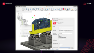
Previously, CAM Assist (available as a plug-in for Autodesk’s Fusion software) generated machining strategies with AI for manufacturers using 3-axis CNC machines, helping them to create programs for the machines far more quickly than previously possible. The new upgrade means CAM Assist can now provide strategies and toolpaths for 3+2 axis components as well, which CloudNC estimates will help around two-thirds of the CNC machining market.
CAM Assist uses advanced computer science techniques and AI to generate intuitive machining strategies in minutes or seconds, depending on complexity, which could take CNC machine programmers hours or even days to manually create. As a result, the amount of time it takes to program a CNC machine to make a component — a bottleneck in many factories — is greatly reduced, compared to the previous manual programming process, as is the time spent to estimate how much a new component will cost to program.
That gain enables manufacturers using CAM Assist to raise productivity and shorten lead times while also estimating for more work more quickly — saving an average workshop over 300 hours of programming and estimating time a year.
CAM Assist is available for Autodesk Fusion today, both via www.cloudnc.com, and the Autodesk App Store. CloudNC is currently undergoing beta testing in other packages, and expects to launch solutions for those later in 2024.