• Skip to primary navigation
  • Skip to main content
  • Skip to primary sidebar
  • Skip to footer

3D CAD World

Over 50,000 3D CAD Tips & Tutorials. 3D CAD News by applications and CAD industry news.

  • 3D CAD Package Tips
    • Alibre
    • Autodesk
    • Catia
    • Creo
    • Inventor
    • Onshape
    • Pro/Engineer
    • Siemens PLM
    • SolidWorks
    • SpaceClaim
  • CAD Hardware
  • CAD Industry News
    • Company News
      • Autodesk News
      • Catia News & Events
      • PTC News
      • Siemens PLM & Events
      • SolidWorks News & Events
      • SpaceClaim News
    • Rapid Prototyping
    • Simulation Software
  • Prototype Parts
  • User Forums
    • MCAD Central
    • 3D CAD Forums
    • Engineering Exchange
  • CAD Resources
    • 3D CAD Models
  • Videos

Siemens PLM

Simcenter 3D accelerates electromagnetics simulation processes

July 10, 2019 By Leslie Langnau Leave a Comment

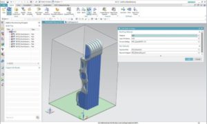
The latest version of Simcenter 3D software includes enhancements for low- and high-frequency electromagnetic solutions to help accelerate electromagnetics simulation processes. This version advances simulation capabilities with increased multidisciplinary integration capabilities, faster CAE process, increased openness and scalability, and enhanced capabilities to integrate with the digital thread.

Including electromagnetic simulation into Simcenter 3D enables engineers to perform electromagnetic simulation faster than with traditional simulation tools and streamline multiphysics workflows between electromagnetic and other physical simulations.

Additional enhancements to Simcenter 3D include:
• Faster CAE Processes: A new immersed boundary method helps engineers spend less time modeling for computational fluid dynamics (CFD) analysis. Engineers can also instantaneously compute new configurations for flexible hoses and pipes after a design configuration change.
• Open and Scalable Environment: Engineers can use calculated vibrations from common third-party finite element (FE) solvers, ANSYS and Abaqus, and apply those vibrations as loading in a structural or vibro-acoustic solution in Simcenter 3D, which can lead to a better understanding of how vibrations will impact perceived sound by end-customers.
• Tied to the Digital Thread: An enhanced interface between Simcenter 3D and Simcenter Testlab software helps engineers better collaborate with colleagues in the test group. New capabilities available in Teamcenter Simulation help engineers quickly identify which simulations are impacted after a design change.

Siemens Digital Industries Software
new.siemens.com/global/en/

Filed Under: Siemens PLM, Simulation Software Tagged With: Siemensdigitalindustriessoftware

Updates in CAD focus on better simulation

April 19, 2019 By Leslie Langnau Leave a Comment

While the latest upgrades to major CAD systems don’t make major changes to the way those programs operate, they do include significant updates. Here’s a look at some of the biggest enhancements and key features of these programs.

Jean Thilmany, Senior Editor

CAD packages continue to see regular updates, whether a major release, or the minor updates that happen throughout the year. Some updates include major enhancements or new features, as is the case with NX, which now includes machine learning and artificial intelligence features. The company will quit bringing out yearly NX updates, as the software is now offered on continuous release.

Other popular programs like Creo, Solid Edge, SolidWorks, and Autodesk Fusion 360 have seen changes as well. More than one company has changed the way in which they name the new versions of their software and several boast new or enhanced simulation capabilities.

Here’s a look at the most recent updates.

NX from Siemens PLM

In February, Siemens announced an update to its NX CAD software, which now includes machine learning and artificial intelligence features that, by following users’ patterns over time, come to automatically predict their next steps and anticipate their needs.

The programs do this by monitoring the actions of the user and following their success and failures. In that way, the features determine how to serve up the right NX commands and also modify the user interface accordingly, says Bob Haubrock, senior vice President, product engineering software at Siemens PLM Software.

Machine learning is increasingly used in the product design process because it has the power to process, analyze, and learn from large volumes of data, he adds. In this way, designers can more efficiently use software to increase productivity. The ability to automatically adapt the user interface to meet the needs of different types of users in various departments can increase CAD adoption rates at a company, continues Haubrock.

In another recent change, Siemens PLM Software began delivering NX using a continuous release model. This means the software updates are produced in short cycles and are released when needed, at any time.

The model gives NX users faster access to new enhancements and quality improvements, while reducing the efforts needed to effectively deploy NX, Haubrock says. “With automatic updates, customers do not have to search for updates online and will not miss critical fixes. The NX Update mechanism will automatically notify and install important updates as they become available.”

With continuous release, users can turn on “automatic updates” within their system to ensure they always receive the updates. The approach helps reduce the cost, time, and risk of delivering changes by allowing for more incremental updates to applications.

Thus, NX will no longer be identified by a release number and will only be referred to as NX. In other words, there will be no NX13.

The CADmaker says it’s the first major CAD, CAM, and analysis vendor to deliver its products in this way.
The company says the new approach will enable Siemens’ NX users to:
–Receive enhancements faster to help boost productivity
–Have a consistent schedule for updates
–Better plan for the adoption of new technologies
–Reduce deployment costs

Creo from PTC

In February PTC released Creo Simulation Live, which allows engineers to perform simulation in real time on their parametric models because ANSYS simulation capabilities have been integrated with the Creo CAD tool.

Creo Simulation Live, from PTC, lets engineers perform simulation in real time on their parametric models because ANSYS simulation capabilities have been integrated with the Creo CAD tool.

“Every time you make a change in your model, you’ll see the consequences instantaneously in the modeling environment,” says Brian Thompson, PTC senior vice president, CAD segment.

“The goal is to remove the barrier between the CAD and CAE world,” says Andrew Leedy, a PTC applications engineer. “This is targeted toward the engineer or designer rather than the analyst.”

The simulation software runs linear, structural, thermal, and modal analyses. The solver uses GPU rather than CPU for instantaneous analysis, Leedy adds. “So as soon as you make changes to the model it updates the graphics that drive the simulation.

The capability to simulate and design simultaneously helps engineers understand the implications of what they’re making, he adds.

The integrated tool also eliminates the need for the engineer to mesh the model before running a simulation and does away with the post-processing step.

The integrated simulation software from ANSYS is called Discovery Live.

“Engineers can ask ‘What if I add this hole, what will it do to the model?’” he said. “This works on top of the model, it works directly within the environment an engineer is used to.”

The CAD software does require a graphics card that supports the ANSYS tool.

Solid Edge from Siemens PLM

Solid Edge 2019 brings a new naming convention to the tool, which will now be referred to by the year in which it is released. This makes it easier for engineers to identify the release they’re using as well and to identify the products within the Solid Edge portfolio, says Ben Weisenberg, applications engineer at product lifecycle management company Prolim. Weisenberg frequently details Solid Edge updates to the CADmaker’s user community.

Solid Edge 2019, from Siemens PLM, makes it easier for engineers to identify the products within the Solid Edge portfolio. The most significant updates for mechanical designers are tools that allow engineers to model and simulate the entire production process along with the final product.

The most significant updates for mechanical designers are tools that allow engineers to model and simulate the entire production process along with the final product, Weisenberg says.

These include the convergent modeling tools that designers can use to integrate mesh models directly into their workflows. They can use these tools for the milling, casting, and molding of generative designs and 3D printed designs.

Manufacturing constraints allow engineers to optimize the weight and strength requirements of their model. A new design-for-cost feature shows the anticipated cost of the part, to help keep product development on track and within budget.

Updated simulation capabilities include:
–Enhanced structural and thermal simulation, including transient heat transfer.
–Time-based history analysis enables simulation of thermal and cooling performance.
–Free surface flow simulation, lighting and radiation capabilities allow digital “what if” analysis.
–The ability to display simulation results on geometry faces to help engineers make more informed judgments about the model.

SolidWorks from Dassault Systèmes

New features to the program, released in September 2018, let product development teams better manage large amounts of data and capture a more complete digital representation of a design. The program also offers new technologies and workflows that improve collaboration and enable immersive, interactive experiences during design and engineering.

SolidWorks 2019, from Dassault Systèmes, is powered by the company’s 3DExperience platform, which runs the CAD, simulation, and other tools on which designers and engineers rely. Those applications on the 3DExperience platform are tailored to SolidWorks users and mid-market companies.

Other new features include the capability for engineers to interrogate or rapidly make changes to a model through an enhanced large design review capability. Another upgrade gives teams a way to communicate with others not involved in design. With this feature, viewers of the CAD design can add markups to parts and assemblies and then export the marked-up designs as a PDF.

The most recent update from Dassault Systèmes involves the Works portfolio, which will bring applications like SolidWorks together with business solutions like a company’s enterprise resource planning (ERP) system. Typically, ERP systems track all pertinent companywide business processes, including accounting, supply chain, and human resources.

When parent company Dassault Systèmes launched SolidWorks 2019, executives stated that the CAD tool was “powered” by the company’s 3DExperience platform, which runs the CAD, simulation, and other tools on which designers and engineers rely.

Those applications continue to run on the company’s 3DExperience platform and are tailored to SolidWorks users and mid-market companies. They have been folded in the 3DExperienceWorks portfolio.

SolidWorks executives term the new portfolio a “business experience platform.” It provides software solutions for every organization within a company—from design to enterprise resource management, says Bernard Charlès, vice chairman and chief executive officer for Dassault Systèmes. “It’s a way for mid-market companies to tie all processes together, from design to manufacturing.”

Use of the applications across the platform should improve collaboration, manufacturing efficiency, and business agility, he added. Companies can accomplish their work using one cohesive digital innovation environment instead of using a complex series of point solutions that requires jumping between applications and interfaces, Charlès, says.

The software on the platform includes SolidWorks, analysis, simulation, manufacturing, and ERP applications. It is available on-premise and in the public or private cloud. The platform connects data and streamlines business and design processes by providing dashboard templates, managed services, access to industry-focused communities and user groups, and applications specific to a variety of job roles, Charlès says.

Autodesk

Like other CADmakers Autodesk has consolidated its design, simulation, and other computer-aided engineering capabilities in one product, Fusion 360, which is available as a cloud-based product. The product unifies design, engineering, and manufacturing into a single platform, according to Autodesk.

Fusion is a 3D modeling took that includes simulation, visualization, rendering, CAM, and other functions within a single interface. It also includes a 3D animation tool and 2D drawing tools. The product runs on both Windows and Macintosh systems.

In March, updates to that product included the capability to know when a teammate is working on your design at the same time to avoid doing work that will be over-ridden by another designer. When someone is working on the same design, an icon is displayed in the toolbar. By using a mouse to hover over the icon, a designer can see who is working on the same design. If one person makes a change to the design and saves it, the icon in the toolbar will change, letting the designer know that the design now has a newer version.

The toolbar has been updated to include quick access tools and documents tabs that line up with one another for more space on the design desktop.

Also new is a hole-tap tool called taper tapped, which allows designers to choose among a variety of thread types.

Autodesk also maintains its AutoCAD and Inventor CAD tools with no plans to immediately discontinue those products. Those two CAD systems usually see a new release in March of each year; though as of press time Autodesk hasn’t announced 2020 versions of AutoCAD or Inventor.

At Autodesk University in November 2018, Greg Fallon, vice president of business strategy at Autodesk, did announce updates to a collection of tools that work inside Inventor as well as a suite of specialized toolsets now available with AutoCAD.

Two years previously at Autodesk University 2016, company officials said they expect to maintain Inventor for another five to ten years and plan to continue updating it and enhancing functions. The Inventor emphasis will continue to be on industrial machinery design, officials said at that time.

While Inventor may be phased out in favor of Fusion 360, this has not been explicitly stated by Autodesk executives.

As ever, there are too many CAD packages to include in a single roundup. Other applications include IronCAD, TurboCAD, OnShape, Catia, and KeyCreator. All these will include new and updated features in future updates.

As designers and engineers know, when it comes to CAD software, the key phrase is, constant evolution.

Ansys
www.ansys.com

Autodesk
www.autodesk.com

Dassault Systèmes
www.3ds.com

PTC
www.ptc.com

Siemens PLM
www.plm.automation.siemens.com

Filed Under: Autodesk, Creo, Siemens PLM, Software, SolidWorks

NX Software now includes Artificial Intelligence and Machine Learning features

February 19, 2019 By Leslie Langnau Leave a Comment

The latest version of NX software includes an expansion of the Digital Innovation Platform that has been enhanced with machine learning (ML) and artificial intelligence (AI) capabilities. These new features can predict next steps and update the user interface to help users more efficiently use software to increase productivity.

The ability to automatically adapt the user interface to meet the needs of different types of users across multiple departments can result in higher adoption rates, leading to a higher-quality computer-aided technology (CAx) system and the creation of a more robust digital twin.


Machine learning (ML) is increasingly being leveraged in the product design process for a competitive advantage. ML can deliver valuable business insights quickly and efficiently, and it has the power to process, analyze, and learn from large volumes of data. AI and ML can also be used to monitor the actions of the user, their success and failures, to dynamically determine how to serve up the right NX commands and or modify the interface and leverage learned UI usage knowledge for CAx environment personalization.

“There’s always been a capability-usability tradeoff with CAD applications. The more expansive it gets, the more difficult it is to use and master,” said Chad Jackson, Chief Analyst at Lifecycle Insights. “The Adaptive UI in NX, however, circumvents that issue. It guides users, new and old, to the right function at the right time. Many will benefit.”

The Siemens Digital Innovation Platform is continually expanding to enable customers to create the most comprehensive digital twin of a product, the production environment and of the performance of the product. Integrating ML and AI into NX software offers benefits of speed, power, efficiency and intelligence through learning, without having to explicitly program these characteristics. Customers can enhance the design process and reduce time to market.

Siemens PLM Software
www.siemens.com/plm

Filed Under: Siemens PLM Tagged With: siemensplm

• Latest Simcenter 3D release reduces transmission modeling time by 80%

January 29, 2019 By Leslie Langnau Leave a Comment

Manufacturing is changing with the advent of new materials and production methods, making it more challenging to ensure that as-manufactured parts match the as-designed shape. In the latest release of Simcenter 3D, Siemens PLM Software introduces cutting-edge simulation capabilities, stronger connections to the broader Simcenter portfolio, and an expansion of the integrated multi-disciplinary environment to cover an extended simulation solution footprint, which will help engineers reduce the time, cost and effort required to predict product performance. The simulation solution has also been updated to include simulation of the additive manufacturing process and to cover areas such as transmission simulation, aerostructure margin of safety analysis and fluid-structure interaction.

“In order to build accurate digital twins of their products, companies are demanding more innovations in their simulation software,” said Jan Leuridan, Senior Vice President, Simulation & Test Solutions, Siemens PLM Software. “We are continually innovating new ways to streamline simulation processes and deliver greater accuracy. This release integrates more physics and technologies into the Simcenter 3D environment, to help our customers predict real world performance.

Simcenter 3D can automate the creation and simulation of transmission simulation models within a single, integrated environment. Integrating this traditionally multi-step, error-prone process into a single tool can reduce the engineer’s effort by up to 80%, leading to a more efficient simulation process. “Creating a complex transmission multibody model is a time-consuming process, often requiring the use of multiple software tools,” said Horim Yang, Senior Research Engineer, Hyundai Motor Company. “Simcenter 3D is well suited for our engineering purposes and can reduce the overall time spent on transmission modeling and simulation.”

The latest release of Simcenter 3D offers new ties to the digital thread through synergies with the Simcenter portfolio. New connections between Simcenter 3D and Simcenter STAR-CCM+ software enable aero-acoustics and aero-vibro-acoustic simulations, allowing customers to eliminate the source of unwanted noise for improved cabin comfort. Simcenter 3D can also connect with the routing application within NX software to obtain electrical cord layouts and connection points. Simcenter 3D can then simulate electrical cord deformation within moving assemblies so engineers can make sure wire harnesses don’t get caught on moving parts and adjust as needed to cord routing.

Other new features of Simcenter 3D 2019.1 include:
• Simcenter 3D Aerostructures can streamline the end-to-end aircraft structural analysis and margin of safety process by up to 30%.
• Topology Optimization is more robust, easier to use, and adds design objectives or constraints for structural integrity of a part when subjected to critical loads.
• A new additive manufacturing process simulation tool helps manufacturers achieve a quality print that matches the desired shape on the first try, saving resources, cost, and time.

Siemens PLM Software
www.siemens.com/plm

Filed Under: News, Siemens PLM, Simulation Software Tagged With: siemensplm

AM progresses as EOS, Siemens intensify cooperation around industrial 3D printing

October 17, 2018 By Leslie Langnau Leave a Comment

Bruce Jenkins | Ora Research

The race to dominate digital engineering technologies and physical production devices for additive manufacturing just took a significant step forward with a new, tighter cooperation between Siemens and EOS.

EOS, which bills itself—with considerable credibility—as “the world’s leading technology supplier in the field of industrial 3D printing of metals and polymers,” and Siemens announced an intensification of their collaboration to further accelerate additive manufacturing (AM) technology and its application across manufacturing industry. The new level of cooperation comes particularly in the areas of software, automation and drive technology, and use of AM technology:

  • Siemens control and drive components are part of the new EOS M 300 series for metal additive manufacturing.
  • EOS’ job and process management software EOSPRINT 2 now integrates into the AM module of Siemens NX 12.
  • Siemens will introduce an EOS P 500 system for polymer industrial 3D printing into its Additive Manufacturing Experience Center in Erlangen, Germany.

New EOS M 300 series includes Siemens automation and drive technology

EOS says it “expands its portfolio of well proven systems for metal additive manufacturing with the EOS M 300 series. The solution is an automation-ready, future-proof platform that is configurable, scalable and secure. For this, EOS also trusts in control and drive components from the Siemens comprehensive Totally Integrated Automation (TIA) portfolio.”

Said Alfons Eiterer, EOS Head of System Engineering, “EOS puts a strong focus on high quality and reliability in its new developments, while at the same time ensuring dynamical and technological progress. This is the reason we chose Siemens control technology for our new EOS M 300 series. With Siemens we can rely on proven technical components and are well prepared to handle future requirements.”

He continued, “With EOS as a strategic partner in the field of industrial 3D printing, Siemens has not only equipped the EOS M 300 series with components, but also the EOS P 500 wystem for polymer 3D printing on an industrial scale, as showcased first time at last year’s formnext fair.”

EOSPRINT driver for Siemens NX 12 integration

EOS and Siemens say EOSPRINT 2 is an “intuitive, open and productive CAM tool that allows businesses to optimize CAD data for EOS systems. Siemens NX 12 is a seamless end-to-end solution starting with design, via topology optimization and process simulation to print preparation in one user interface.” Now that an EOSPRINT driver for the Siemens NX12 AM module is available, EOSPRINT 2 functions are seamlessly integrated into Siemens’ NX Fixed Plane (Powder Bed) AM software module.

An EOSPRINT driver for the Siemens NX 12 AM module enables seamless integration of EOSPRINT 2 functions into Siemens’ NX AM Fixed Plane (Powder Bed) module software. Source: EOS GmbH

This integration, the companies say, supports Siemens’ overall additive manufacturing solution offering, which “helps to deliver an integrated and associatively linked additive manufacturing process from design to advanced 3D printing with EOS systems. As a result, engineers benefit from a quick and uninterrupted path from product idea to 3D printed part.”

EOS P-500 becomes part of Siemens Additive Manufacturing Experience Center

Siemens says it is going to extend its Additive Manufacturing Experience Center (AMEC) in Erlangen, Germany with the EOS P 500 system. The AMEC, says Siemens, “provides an excellent overview and insight into different industrial AM technologies and information about the challenging industrial requirements for AM-design, simulation and production. It also offers an interactive experience where the integrated, seamless AM chain and the AM-relevant products of Siemens are shown.”

“A fast industrialization of additive manufacturing can only be unleashed by a close cooperation of experts from a software, automation and drive-system angle with industrial 3D printing experts, as is the case with Siemens and EOS,” remarked Dr. Karsten Heuser, VP of Additive Manufacturing at Siemens AG. “We are therefore proud to move with EOS into the next level of industrialization, which will help transform additive manufacturing further from the prototyping phase into industrial serial production.”

EOS

EOSPRINT 2

EOS P 500

Additive Manufacturing Experience Center (AMEC)

Filed Under: Company News, Siemens PLM Tagged With: Siemens

How driverless cars will change design

October 16, 2018 By Leslie Langnau Leave a Comment

Automated vehicles (AVs) will disrupt the way mechanical engineers work with their peers and how they share design information. Here’s what you can expect.

Jean Thilmany, Senior Editor

Tomorrow’s vehicles will be electrified, connected, and will include many automated functions, including the capability to navigate roads on their own—without a driver’s intervention.

In other words, they’ll be incredibly complex systems comprised of mechatronics, sensors, radar, automated functions, and many other features. And, like other incredibly complex systems introduced within recent years, they’ll disrupt the way mechanical engineers work with their peers and share design information.

The age of the automated vehicle (AV), also known as the driverless car, is upon us, says Scott Shogan, connected and automated vehicles market leader at WSP, an engineering firm.

Government officials and industry leaders expect AVs will begin to make their way to U.S. streets within the next decade, says Shogan, who follows AV trends on the local, national, and international levels.

Future automated vehicles will consist of complex systems that are comprised of mechatronics, sensors, radar, automated functions, and many other features.

AVs probably won’t be the personal, driverless cars you may be imagining—instead, they’re likely to take the form of shared-ride cars or small buses that pick you up at your home. The driverless vehicle will shuttle you from your door to the nearest automated-bus stop or train station to continue you on your driverless commute, says Shogan.

While AVs may not yet be on the scene, connected vehicles—AVs cousins—are increasingly common today. They include features like advanced driver’s assistance systems with lane centering, adaptive cruise control, and swerve detection, notably seen on Tesla vehicles.

ACM uses Prescan, part of the SimCenter suite of Siemens simulation and test solutions. Designers use the program to physically and virtually test and validate AVs and connected vehicles. The program produces physics-based simulation of raw sensor data of the potential driving scenarios and traffic situations in which AVs could drive themselves. These simulations help developers better understand how to position Lidar and radar on their vehicles, as well as improve upon many other aspects of design.

None of these features let the car drive itself, but they do help a driver avoid crashes, Shogan says.

The move toward electric is already underway. GM has announced it will launch AV taxies next year at three sites, Shogan says. “What they’ll look like we don’t know. But it shows how quickly things are moving.”

Volvo announced it will stop making internal-combustion-engine vehicles in the next few years, Shogan says.

Already there are around 350 types of electrical vehicles on the market, O’Brien says. “There has been a huge increase in the complexity of these electrical systems,” he adds.

Future electric vehicles will use sensors to gather instant information about what’s going on in the world around the vehicle to help automated systems make split-second decisions.

They’ll also include 40 percent more hardware than today’s vehicles and have safety, security, and power demands not seen in present-day automotive needs.

Systems of design

As you might expect, automated vehicle design is a different ballgame as compared to the way non-automated and non-connected vehicles are designed today. Whether connected or automated, these vehicles will likely be built on an electric platform, Shogan says.

Engineering AVs and other new, complex machines like collaborative robots require close collaboration among engineers who must take a “systems engineering” approach to design, validation, testing and prototyping, says Martin O’Brien vice-president of the integrated electrical systems division at Mentor, which makes software for electronic design.

Like cobots, AVs will consist of electrical, mechanical, and software systems as well as sensors that provide feedback about the world around the vehicle, he says.

While CAD has a place in automated vehicle (AV) design, CAD models are part of all the models that make up the larger design system, O’Brien says. The CAD models become part of a model-based system engineering process,

Which is a method of systems engineering based on creating and exchanging models rather that documents.

In July, Volkswagen confirmed plans confirmed plans to produce its upcoming all-electric microbus and its crossover vehicle in the United States.

All the systems within complex machines like AVs need to be designed to work together, O’Brien says. So software and mechatronic models are shared for a systems-engineering approach to design.

A systems-modeling approach allows engineers to bring together all the knowledge from the multiple domains into one location, he says.

“Systems that used to be tested independently of one another are now so tightly integrated that we have to engage all the systems and test them simultaneously,” he says. “The electrical system has to be designed in the context of the software system and the entire 3-D system.”

Recognizing this, the makers of engineering software are increasingly creating software that can help carry out the design of AVs across the lines of engineering—electrical, mechanical, and software.

The software depicts how all these functions will work together in a real-life operating machine. When the digital systems are all running at the same time and in intended manner, developers often refer to the product mock-up as a digital twin.

SimCenter 3D, from Siemens PLM Software, for example, allows engineers to create models to connect their designs and to carry out 1D simulation, test, and data management functions on those designs, says Dave Taylor, Siemens vice president of global marketing.

While the solution is tied to Siemens NX CAD software on the mechanical-creation side, it can import geometry from any CAD source and prepare analysis models for a range of multiphysics simulations including finite element, boundary element, computational fluid dynamics, and multi-body dynamics, Taylor adds.

Usually a company will use its product lifecycle management system to coordinate efforts across various applications, he adds. To take the Siemens example, Teamcenter PLM, from Siemens, can be used to coordinate mechanical designs created with Siemens’ NX software, and electrical designs created with Capital electrical design software from Mentor, a Siemens company, O’Brien says.

Once it meets everyone’s specifications, the model of the entire system—the entire AV in this case—becomes the digital twin, used to virtually test the AV. Because the digital twin simulates exactly how a machine will function, engineers are able to find and fix design problems before the expensive products are produced.

This is where the digital twin comes in. The digital twin links those models to focus on one aspect of a product or the entire product.

While the CAD model is a part of a digital twin, so are the models that make up the electrical and software systems. Sensor information is incorporated into the digital twin as well, O’Brien says.

“Developing a functioning twin is a systems integration task,” he adds. “Model-based engineering is central to successful outcomes to integrate functions, devices and signals into the platform.”

Simcenter allows engineers to share their model across domains to create a system-wide simulation of a product to be used for a digital twin, Taylor says.

A digital twin is increasingly used for testing today because building a prototype to test all the functions of sophisticated machines like an AV or a collaborative robot is often just not possible, O’Brien says.

“Multi-physics simulation is critical for autonomous vehicles, where the digital twin can drive billions of virtual miles and our solutions can predict exactly what’s going to happen in the real world,” Hemmelgarn adds.

Some parts of the AV won’t require a systems-engineering approach.

The way CAD works in the automotive industry today will still be part of the design process when other aspects like electric and software don’t come into play, for example, for the features found inside the AV.

Of course, the interior of the vehicle will look quite different than it does today, as there won’t be a need for the steering wheel, or really, the driver’s seat. To save space within the vehicle’s compartment, riders might sit facing each other, or they may not sit at all, Shogan says.

But a seat is still a seat. And mechanical engineers will be called upon to use their CAD systems for seat design.

Perhaps the interiors of some AVs will look like the trains in airports that ferry passengers between terminals: they’ll include a few seats around the perimeter, though most of the AV’s occupants will remain standing for their short ride.

On the right track

But testing and validating AV design goes beyond the digital twin, of course. Testing the AV needs to happen with a real-life vehicle.

Safe validation must include a structured combination of three methods: testing the digital twin, testing the vehicle on a controlled track, and testing it on the actual road, says Mark Chaput, vice president of construction and infrastructure development at the American Center for Mobility (ACM) in Ypsilanti Township, Mich.

The Michigan center is an AV proving ground where the technology can be tested safely. The U.S. DOT designated 10 of these sites in 2017. After a testing period, officials from those sites will their share best practices to safely test and operate AVs. That information will enable participants and the public to learn about AVs and will accelerate the pace of safe deployment, Chaput says.

ACM is an open track that companies come to independently to test their AVs. AVs can operate at the proving grounds much as they would on the street, so engineers can get sensor feedback and, of course, perfect their vehicles.

The proving grounds are necessary because these prototypes need to be tested within a closed environment.

“You won’t be able to develop this technology in a traditional way,” Chapaut says. “Vehicle makers need to test perceptions of the world around the AVs and traditional automotive proving grounds aren’t equipped for that.”

The test vehicles will need to be tested across millions of miles to verify all its technological functions, he adds. “AV makers, for example, wonder how to integrate Lidar and radar and the many sensors needed to automatically see the road into their AVs,” he says.

Lidar allows AVs to calculate the distance to an object. It measures the distance by illuminating a target with pulsed laser light and measuring the reflected pulses with a sensor.

In May, ACM brought in Prescan, part of the SimCenter suite of Siemens simulation and test solutions. The program is used to physically and virtually test and validate AVs and connected vehicles.

It produces physics-based simulation of raw sensor data of the potential driving scenarios and traffic situations in which AVs could drive themselves. By running these kinds of tests and simulations, developers can better understand how to position Lidar and radar on their vehicles, as well as improve upon many other aspects of design.

When the AV prototype is finally ready, it can be tested in real life, on the ACM roads, which include stoplights, curbs—essentially everything found while driving on a road, including bikes and pedestrians, Chaput says.

When driveless vehicles finally do become a common part of the landscape, you’ll know the time, commitment, collaborations, and the many tests and validation scenarios that went into their safe creation.

Siemens PLM Software
www.plm.automation.siemens.com

Filed Under: Siemens PLM Tagged With: siemensplm

Boeing extends partnership with Siemens’ Mentor Graphics

October 2, 2018 By Leslie Langnau Leave a Comment

Siemens announces that Boeing has entered into an agreement to expand its use of Siemens’ Mentor Graphics software as part of its Second Century Enterprise Systems (2CES) initiative to transform itself, and the aerospace industry, to meet the challenges of the twenty-first century. As the world’s largest aerospace company, Boeing stands ready to lead the industry into the next 100 years with Siemens as a partner, providing a set of technologies to enable the next generation of design and manufacturing through increased automation and digitalization.

This decision follows a comprehensive analysis of available solutions including current and future capabilities, technology flexibility to meet changing requirements in real world applications and overall business value to Boeing. The long term agreement provides industry-leading Siemens technology in the areas of electrical systems design, electronic products design and mechanical analysis as a foundation for Boeing to consistently deliver comprehensive and innovative solutions to its customers. Focusing on technologies from Siemens’ Mentor Graphics acquisition, Boeing will standardize on a common, company-wide platform for semiconductor design and verification, printed wire board design and manufacture, electrical system design and manufacture (including wire harness) and thermal and fluid analysis of mechanical designs.

“Our partnership with the Siemens-Mentor team will combine best-in-class electrical design tools with Boeing’s vast experience and knowledge in our 2CES transformation of electrical design,” said John Harnagel, Engineering Director, Boeing Defense and Space.

“Siemens is proud to have been chosen as one of Boeing’s partners for its second century vision and transformation. Our ability to help customers drive digitalization and realize innovation is our core strength, and we are pleased to see that Boeing values that strength,” said Tony Hemmelgarn, president and CEO of Siemens PLM Software. “This partnership is a measure of Boeing’s trust in Siemens to help them deliver its vision, and we at Siemens are looking forward to helping them make it happen.”

Siemens PLM Software
www.siemens.com/plm

Filed Under: Company News, Siemens PLM Tagged With: siemensplm

The perfect, unorthodox design

June 15, 2018 By Leslie Langnau Leave a Comment

What if you could create the perfect part unlike anything that exists today? New CAD tools combined with 3D printing can make that happen, makers say.

Jean Thilmany, Senior Editor

No matter what you call the design method, having the computer generate the designs from am engineer’s directions may just be the future. Unorthodox, 3D printed shapes can be found in aerospace now. Soon, such designs will be all around you.

3D printing methods are enabling the development of shapes unproducible by other manufacturing methods. Now, CAD developers are including design tools that take full advantage of the capabilities of 3D printing. These tools are often labeled generative design or topology optimization. They enable engineers to use design software in a new way to best fit design needs.

In April, Autodesk released generative design to subscribers of its Fusion 360 Ultimate product development software. The design concept allows engineers to define design parameters such as material, size, weight, strength, manufacturing methods, and cost constraints–before they begin to design. Then, using artificial-intelligence-based algorithms, the software presents an array of design options that meet the predetermined criteria, says Ravi Akella, director of product management at Autodesk.

“Our effort now is in helping people define the problem they’re trying to solve,” Akella says. “That’s a shift in focus in this industry and makes people have to change the way they have to work.

“The software asks the user preliminary questions. ‘What sorts of materials would you consider for your design? Where does it connect with other things as part of an assembly? What are the loads? What are the pieces of geometry?’” Akella says.

This Elbo chair was designed using Project Dreamcatcher, which was the name Autodesk used for its generative design tool before officially unveiling it this spring.

The software then presents designers and engineers with an array of design options that best meet their requirements. Designers choose the best option. Or, if none of the options meet their needs, they can begin the generative process again, this time offering slightly different inputs.

The computer-generated (“generative”) designs might be unorthodox, new, and unexpected, with geometries that wouldn’t naturally occur to the designer. Yet, no matter how different, if the design is shown to work, it can be created through additive manufacturing,” Akella says.

The method adds value to the present way designers use CAD software, he adds.

“None of these generative questions are asking ‘What is your solution and please start documenting it,” he says. “Without generative design, it’s like engineers were using a piece of paper to explain the problem to themselves. Our job is to get all of that into software.”

He compares generative design with the job of the wine merchant.

By using Autodesk’s generative design and additive manufacturing technologies, engineers at Stanley Black & Decker shaved more than three pounds off this crimping tool attachment, reducing the weight by more than 60%.

“Someone walks into a wine store and wants a Cabernet Sauvignon,” he says. “To get the best version you go in and say ‘It’s summer and this is what’s on my dinner menu’ and you’re trusting the sommelier to present you with a variety or vintage you’ve never heard of.

“Generative expands your solution options, which sometimes aren’t intuitive,” Akella adds. “Users look at their results and think ‘I never would have thought of it. I’m not sure it’s the right answer but I’m going to check it out further.”

By any other name?

Akella takes issue with what he calls “technologies that masquerade as generative design,” which, he says, include topology optimization, lattice optimization, or parametrics.

“Topology optimization assumes you have a solution you’ve thought of and are making a better version of that solution,” he says. “But generative design expects the user to define the problem they’re trying to solve. Then we use cloud computing and other technologies to present them with a set of solutions that solve their problem in a practical, manufacturable way.”

Generative design produces many valid designs instead of an optimized version of an already-modeled part.

“Optimization usually involves removing excess material without any notion of how something is made or used,” he says.

Generative design also takes manufacturability into account, which reduces an engineer’s need to redesign products after manufacturing weighs in, Akella says.

But developers and executives at other makers of CAD technology may take issue with that depiction of their topology optimization features, which can radically change designs and reduce weight and slash costs, they say.

SolidWorks introduced topology optimization capabilities into its recent release of SolidWorks 2018 Simulation Professional and Simulation Premium.

“We expect the computing platform to anticipate your design goals,” said Gian Paolo Bassi, chief executive officer at Dassault Systèmes SolidWorks, when he spoke at SolidWorks World 2018 in January.

“The era of design and validate is about to end. We are entering the era of optimize and manufacture,” Bassi said.

That means designers specify the aspects of the part they absolutely need, including loads, constraints, boundary conditions, and manufacturing methods. The CAD tool then supplies many versions of a near-optimized part, Bassi says.

Topology optimization can be an additive or subtractive algorithm, meaning it can create parts based on user inputs like loads and boundaries or it can subtract from an existing design by essentially chiseling away at the part, says Robbie Hoyler, a SolidWorks elite application engineer for TPM, an engineering services and design provider in Greenville, S.C.

SolidWorks uses the subtractive method. It creates a meshed part based user-defined loads, constraints and boundary conditions. The software cuts out elements that offer few structural or manufacturing benefits. This process is then repeated until the part meets all constraint requirements, Hoyler says.

The optimized CAD design shows engineers the areas of the part that need to stay and the areas where material can be removed, Hoyler says. He cited an example in which SolidWorks topology optimization reduced the weight of an existing part by 50% without removing areas designers had flagged as necessary.

The part can then be saved as a mesh body in the stereolithography (SL) format for 3D printing or can be retraced as a new SolidWorks part.

Another software package, Inspire, also features generative design and topology optimization tools. It allows users to save the enhanced design as a CAD model (skipping the retracing step). The software is from Altair channel partner solidThinking.

The Inspire’s generative feature is easy to learn and is ideal for small and medium-size businesses with little or no simulation experience, says James Dagg, Altair’s chief technology officer for user experience.

Solid Edge, from Siemens PLM Software, of Plano, Texas, also includes a generative design feature that brings topology optimization to the Solid Edge 3D product development toolkit, according to the company. With the feature, designers define a specific material, design space, permissible loads and constraints and a target weight, and the software automatically computes the geometric solution.

The results can be immediately manufactured on 3D printers, or further recreated as a Solid Edge model for traditional manufacturing. Designers can run multiple weight targets, load cases and constraint scenarios simultaneously, according to Siemens PLM.

Refining the real world
Recently, engineers at automaker General Motors began putting Autodesk’s generative tool to the test to cut weight from GM vehicles. Lighter cars use less fuel, emitting less carbon.
Since 2016, the automaker has launched 14 new vehicle models with a total mass reduction of 350 pounds per vehicle, says Ken Kelzer, GM vice president of global vehicle components and subsystems. The 2019 Chevrolet Silverado, for example, reduced mass by up to 450 pounds as compared to earlier model years.

To further lighten the load, as it were, in May the automaker announced an alliance with Autodesk that will use additive manufacturing and Autodesk’s generative tool to develop future cars and trucks, Kelzer says. The pairing of additive and generative capabilities is a natural for the automaker, Kelzer adds.

GM has used additive technologies for more than 30 years to print 3D parts. The automaker has more than 50 rapid prototype machines that have produced more than 250,000 prototype parts over the last decade, Kelzer says.

And the generative capabilities now included in the Autodesk CAD systems put those printers to work in unique ways, he adds. “When we pair the design technology with manufacturing advances such as 3D printing, our approach to vehicle development is fundamentally different; to co-create with the computer in ways we simply couldn’t have imagined before, Kelzer says.

But the design of formerly unimaginable parts doesn’t mean the engineer lacks ingenuity. Rather, those reduced weight, and perhaps rather odd-looking shapes are the whole point of the generative process, which provides thousands of solutions to one engineering problem, Akella says.

He gives the example of a designer who wants to create a chair. Typically, the designer would start with some geographical representation of the chair humans have taken for granted for centuries; that is, four legs, a seat, and a back. But if the designer were to begin by specifying the amount of weight the chair must support, the materials it will be comprised of, and its cost, “the designer will get hundreds or even thousands of options he or she couldn’t have conceived of on their own,” Akella says.

The nature of the creation process also allows for a part with such complex geometries that it can replace multi-part assemblies. And they can be created with 3D printing, he adds.
The process is also being tested in other industries that design with CAD tools.

For instance, architects at Arup, the building and infrastructure design consultancy in the Netherlands, paired topology optimization and additive manufacturing to redesign a steel node for a unique, public lighting and artistic tensegrity structure.

Needle Tower, public art by American sculptor Kenneth Snelson demonstrates the concept of tensegrity. The piece is located outside of the Hirshhorn Museum and Sculpture Garden in Washington, D.C.

Buckminster Fuller coined the term tensegrity to refer to a structure that uses the principle of floating compression, with parts compressed inside a net of continuous tension with cables or tendons delineating the system. Think, of course, of his famous geodesic domes.
Arup designers created their trio of tensegrity structures for a shopping street, the Markstraat, in The Hague. Unveiled in 2013, the “urban chandeliers” integrate street lighting and add an artful element to the area.

Arup architects designed several variations of the node using conventional and optimization techniques. The third figure, on the right, is the final, lightest shape attained through topology optimization.

The urban chandeliers are beautiful. But they weren’t easy to create, says Salomé Galjaard, an Arup senior designer for the project.

Due to the irregular shape of the structures most of the 1,600 nodes that connected the cables to the struts, were different due to the more than one thousand variations in angle and position of the attached cables, Galjaard told attendees at the 2015 Future Visions symposium in Amsterdam.

The Arup architectural firm created this 3D-printed, optimized node for a study of nodes used in its urban chandeliers street-lighting project in The Hague.

“This ‘uniqueness’ inspired us to learn more about additive manufacturing,” she says.
Curious as to what optimization could have done for them on a project like the urban chandeliers, Arup designers conducted a study. Both topology optimization and additive manufacture have been little used in the architectural world, so this seemed like an excellent opportunity.

After performing topology optimization, using the Optistruct software from Altair, they found the node they’d modeled traditionally closely resembled the optimized node. And yet, that optimized design reduced the weight the node from 44 pounds to 11 pounds, a 75% drop, without compromising the functional and structural performance of the product, Galjaard says.

Still, the designers spent much more time working with the complex, optimization software than they normally would, and the process could be frustrating, she says.

“Our research illustrates that 3D printing can have a positive impact on the design and production process and the functional product,” she says. “The resulting costs of future construction products could be decreased significantly, whereas architectural freedom will be increased dramatically.”

Generative design and topology optimization can bring the same design freedom and cost reduction to engineering and other types of design of course. Imagine a complex, oddly shaped part that is printed and performs as an assembly. In other words, a part beyond your imagining. That’s the promise of generative design and topology optimization.

Altair
www.altair.com

Autodesk
www.autodesk.com

Dassault Systèmes
www.3ds.com

Siemens PLM Software
www.plm.automation.siemens.com

Filed Under: Autodesk, Featured, Siemens PLM, SolidWorks

Solid Edge delivers next-generation product development tools in an integrated portfolio

June 5, 2018 By Leslie Langnau Leave a Comment

Siemens  announced the latest release of Solid Edge software, a portfolio of affordable, easy-to-use software tools that advance all aspects of the product development process, including mechanical and electrical design, simulation, manufacturing, technical documentation, and data management. Solid Edge 2019 adds best-in-class electrical and printed circuit board (PCB) design technologies, new requirements management capabilities, fully integrated simulation analysis, the latest tools for subtractive and additive manufacturing, and free secure cloud-based project collaboration. The expanded portfolio makes it even easier for customers of all business sizes to realize innovation by taking advantage of the end-to-end digital twin.

“The integration of mechanical and electrical design tools within Solid Edge will enable us to develop and deliver our custom electro-mechanical systems faster and at a lower cost than our competition,” said Eric Becnel, VP and chief engineer, RadioBro Corporation.

Integrated software applications are critical for today’s complex multiphase design projects. Solid Edge Wiring Design provides design and simulation tools for the rapid creation of wiring diagrams and verification of electrical systems. Solid Edge Harness Design adds intuitive harness and formboard design tools with automated part selection, design validation, and manufacturing report generation. Solid Edge PCB Design accelerates schematic capture and PCB layout, and is fully integrated with mechanical design to reduce costly errors.

The latest release of Solid Edge provides new modular plant design capabilities, with Solid Edge P&ID Design and Solid Edge Piping Design. Providing 2D flow diagram and symbol support for P&ID creation, Solid Edge P&ID Design supports strict governing requirements for plant design. Combined with Solid Edge Piping Design capabilities such as automated 3D piping design with comprehensive 3D part libraries and fully automated isometric drawing output for plant design, these new features can help reduce design errors and ensure efficient piping design in industries such as Oil & Gas.

New design for additive manufacturing capabilities include better control of shapes, weight and strength, and specific factors of safety to enable customers to develop new designs never before possible. Solid Edge also automates print preparation, including multi-color, multi-material printing capability, which reduces bill of material size and parts inventory and decreases dependency on costly manufacturing equipment. Additionally, these new capabilities enable manufacturers to produce low production lots very quickly and affordably. Also new in Solid Edge 2019 is Solid Edge CAM Pro, a comprehensive, highly flexible system that uses the latest machining technology to efficiently program CNC machine tools helping confirm parts are manufactured as designed.

“The global market requirement to develop and deliver increasingly complex products in shrinking timeframes has created many new challenges for our customers, as well as new opportunities to differentiate,” said John Miller, senior vice president, Mainstream Engineering, Siemens PLM Software. “I’m confident that the integration of leading technologies from Mentor and the next-generation design capabilities delivered in the Solid Edge 2019 portfolio will empower our customers to innovate in the new era of digitalization.”

Siemens PLM Software
www.siemens.com/plm/solidedge2019

Filed Under: Siemens PLM Tagged With: siemensplm

Siemens partnership with Obeo enables a multi-domain digital twin

June 5, 2018 By Leslie Langnau Leave a Comment

Siemens PLM Software announced extensions to its portfolio for model based systems engineering (MBSE) to enable Multi-Domain Engineering as a key component of the Systems Driven Product Development strategy.

Building on its MBSE technology, which includes Teamcenter software, Simcenter software, Capital software, NX software, and Polarion software, Siemens PLM Software is embracing a strong commitment to open standards and the open source software enabling these technologies to integrate with the digital twin. For this purpose, Siemens PLM Software has entered into a partnership agreement with Obeo, a software provider of customizable modeling solutions.

The partnership will complement Siemens’ Multi-Domain Engineering capability by providing flexible modeling solutions, engineering methodologies and industry-specific process templates. These offerings allow customers the flexibility to either use standard modeling languages, such as System Modeling Language (SysML) or Capella, or to apply their own process methodology. Providing cross-discipline integration across the product architecture helps connect digital twins in a unique way, creating a multi-domain digital twin by enabling systems engineering across the entire product lifecycle.

“With this partnership, Obeo brings users of Siemens PLM Software the benefits of closed-loop model integration between product architecture and downstream engineering,” said Etienne Juliot, vice-president and cofounder of Obeo. “Managing the system, software and hardware architecture characteristics in an integrated repository that is ‘single source of truth’ uniquely enables a digital thread across the digital twins, and therefore the best way to find an optimal trade-off between reliability, cost, and performance to master multi-domain system development.”

Through the Systems Driven Product Development solutions, Siemens offers the next-generation capability to provide a clear step beyond existing point-to-point software integrations. The combined solution, underpinned by the collaboration platform Active Workspace for Teamcenter, can be used to optimize designs for cost, performance and in-service maintenance, and to deliver continuous validation against requirements. The user experience is augmented by co-design aids such as cross visualization and automatic object reconciliation between NX, Simcenter and Capital, our integrated electric and electronic design and validation platform. The true integration of MBSE with the entire product lifecycle through Teamcenter helps enable a more efficient product journey from conceptualization to realization.

Integrated with Teamcenter, the combination of NX CAD, Simcenter for mechatronic systems simulation, and Polarion for embedded software development enables systems engineering across all major engineering domains. Such systems engineering workflows were recently extended into the domains of electrical and electronic engineering, with the applications of Mentor Graphics. The partnership with Obeo will help provide a seamless integration between Siemens’ MBSE solution and industry standards. The solution will deliver comprehensive requirements, including functional, logical, physical and flow, giving customers the richest and deepest set of capabilities for MBSE to uniquely address and simplify the development of complex products.

Siemens PLM Software
https://www.plm.automation.siemens.com/global/en/products/collaboration/mbse-model-based-systems-engineering.html

Filed Under: News, Siemens PLM Tagged With: siemensplm

  • Go to page 1
  • Go to page 2
  • Go to page 3
  • Interim pages omitted …
  • Go to page 8
  • Go to Next Page »

Primary Sidebar

3D CAD NEWSLETTERS

MakePartsFast

Follow us on Twitter

Tweets by 3DCADWorld

Footer

3D CAD World logo

DESIGN WORLD NETWORK

Design World Online
The Robot Report
Coupling Tips
Motion Control Tips
Linear Motion Tips
Bearing Tips

3D CAD WORLD

  • Subscribe to our newsletter
  • Advertise with us
  • Contact us
Follow us on Twitter Add us on Facebook Add us on LinkedIn Add us on Instagram Add us on YouTube

3D CAD World - Copyright © 2021 · WTWH Media LLC and its licensors. All rights reserved.
The material on this site may not be reproduced, distributed, transmitted, cached or otherwise used, except with the prior written permission of WTWH Media.

Privacy Policy