• Skip to primary navigation
  • Skip to main content
  • Skip to primary sidebar
  • Skip to footer

3D CAD World

Over 50,000 3D CAD Tips & Tutorials. 3D CAD News by applications and CAD industry news.

  • 3D CAD Package Tips
    • Alibre
    • Autodesk
    • Catia
    • Creo
    • Inventor
    • Onshape
    • Pro/Engineer
    • Siemens PLM
    • SolidWorks
    • SpaceClaim
  • CAD Hardware
  • CAD Industry News
    • Company News
      • Autodesk News
      • Catia News & Events
      • PTC News
      • Siemens PLM & Events
      • SolidWorks News & Events
      • SpaceClaim News
    • Rapid Prototyping
    • Simulation Software
  • Prototype Parts
  • User Forums
    • MCAD Central
    • 3D CAD Forums
    • Engineering Exchange
  • CAD Resources
    • 3D CAD Models
  • Videos

Simulation Software

How to combine 1D and 3D thermal simulation for modeling aircraft fuel systems

December 12, 2019 By Leslie Langnau Leave a Comment

Leveraging advanced 3D CAD-embedded CFD capabilities can add robustness and fidelity to a 1D system model.

By Mike Croegaert, Siemens Digital Industries Software

A common issue with modeling complex 1D systems is adding the required detail for complex components that cannot easily be represented through correlations or empirical data. To get the data for these types of components, engineers have two options: physical testing and 3D computational fluid dynamics (CFD) simulation and analysis. Physical testing can be costly and obtaining the data can be difficult for all possible operating scenarios. Whereas, 3D CFD can be time-consuming and often requires an expert to get reliable results.

Fortunately, we now have the option to use advanced 3D CAD-embedded CFD solutions in conjunction with 1D CFD tools to quickly and accurately characterize complex components without the need for a specialist, while providing an added level of robustness to a complex system model.

The basic fuel system: solving pump limitations
To illustrate the effectiveness of using this combination, a simple passenger aircraft fuel system example will be used. Figure 1 shows a 1D system model drawn on top of the basic fuel system schematic image. It includes source components for the boundary conditions and extra loss components for items such as filters and couplings. The thin link lines represent a direct connection between adjacent components, but they are not pipes themselves. Nodes sit in the middle of the links and serve as convenient points to enter elevation data and interrogate flow results of temperature and total pressure.

Figure 1: Basic aircraft fuel system schematic. The three large blue sections represent the wing and the center fuel tanks, the white boxes represent pumps, and the fuel feed and transfer plumbing is represented in green. The refueling lines are represented in dark blue. Shut-off valves are depicted throughout the model as the circular symbols, indicating normally open or closed.

During normal operation, the fuel is drawn from the tanks with mechanical fuel pumps. However, most mechanical pumps must be fully wetted to function properly. This means sometimes unusable fuel is left in the bottom of the tank. To extract the residual fuel, jet pumps can be added with the suction side connected to the lowest sump point on the inner wing tank. This pump feeds the collector cell by using the motive energy provided by a small amount of high-pressure fuel bled directly from the mechanical fuel pumps. For this example, the jet pumps are placed in the lowest portion of the tank.

In contrast to most other components, this jet pump does not come pre-supplied with performance data. That leaves the designer with two options to define performance. The first method is to enter detailed geometry for the pump and the 1D CFD tool can apply a built-in empirical correlation for jet pump behavior. The second option is a more rigorous databased approach. The pump requires a curve of flow ratio versus head ratio and a curve of motive flow rate versus pressure difference between the motive and suction arms. This data can come from many sources, including the vendor of the pump, physical testing, or 3D CFD characterization and analysis.

3D-1D characterization
Sophisticated 3D CAD-embedded CFD programs have key technologies that facilitate 1D data generation. These tools can be used by the typical engineer as well as seasoned CFD analysts. They apply automated modified wall functions to capture boundary layer effects properly, regardless of the density of the mesh in the boundary layer. They also have an automated solver to determine the flow regime between laminar, turbulent, or transitional without intervention. The most advanced 3D CAD-embedded CFD software has a unique and automated mesher that is geometry aware. If the CAD geometry changes, the mesh changes automatically, updating as the problem solves, intelligently putting more mesh where it is needed. Because these tools are completely CAD-embedded, the designer can run parametric studies, by not only varying flow conditions, but also changing the actual geometry over the course of a study, feeding data back to the 1D CFD software as seamlessly as possible.

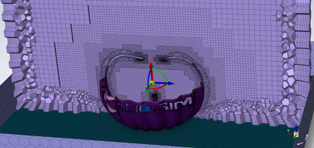
Using an intuitive graphical interface, the designer inputs the key variables—choosing the units, the physics to consider in the simulation (including heat transfer, gravity effects and rotation), the fluids to use in the simulation, and lastly, the initial conditions such as temperature, pressure, and initial velocity. The 3D software then calculates a computational domain surrounding the relevant fluid geometry. The design engineer can resize the domain area or even slice the volume in half and do an axisymmetric simulation to save computational resources. The mesh (Figure 2), although highly automated, can be manually driven to add grid cells where needed and manually refined by selecting specific geometry, adding optional control planes, or even disabled bodies into the CAD model to serve as the mesh structure.

Figure 2: 3D CAD-embedded CFD adaptive mesh.

Once the model is prepared, the boundary conditions set, and goals determined, the simulation is ready to run launching the solver. The solver is the only aspect of 3D CAD-embedded CFD that does not operate directly in the CAD environment. Instead, a second window is launched to monitor the progress of the solution. Custom-defined preview plots for parameters such as pressure, velocity, and even the mesh can be created. Goals can also be plotted to have a real-time monitor on current value and their trend toward convergence. Parametric studies can also be performed on multiple machines at once to improve performance.

Once complete, the results are loaded back into the CAD interface, the first example of a result is a cut plot that shows the contours of velocity with overlaid streamlines (Figure 3). The cut plane can be manually adjusted with a live preview. 3D CAD-embedded CFD can also generate three dimensional flow trajectories inside of the fluid region.

Figure 3: Sample results from 3D CAD-embedded CFD.

Typically, for characterizing a component using 1D CFD software, multiple simulations are needed to generate data over a range of flow conditions. Once the study is complete, the results can be saved to a file that acts as a raw record of the flow conditions at each boundary at each experiment point. Each point contains data for flow rate, pressure, temperature, density, viscosity, enthalpy, and heat capacity. From this data, non-dimensional curves can be created so that the software can extrapolate performance of the part over a range of fluids, temperature, and pressures.

After the curves are created, they can be imported into the 1D CFD tool either as an individual data curve or as a complete component. The software will parse the data and automatically determine what type of component to create. Once this step is done, the 1D CFD software adds the component to the catalog and automatically populates it with the data just generated.

Before using the component in the fuel system model, it will first be verified in a unit test. Unlike most components, components sourced from the 3D CAD-embedded CFD program require no further data to use because relevant data such as the curves are pre-applied. All that is required to run a unit test is to add boundary conditions and run an analysis, and the component should perform exactly as the software predicted during the characterization step. After the unit test has verified the component was created correctly, the jet pump can be added to the fuel system model (Figure 4), and the designer can run a series of analyses.

Figure 4: Adding the characterized jet pump to the system model.

In this example, two transient simulation scenarios will be examined. In the first simulation, the jet pump has been included but blocked the motive flow, so the tanks will only feed into the collector cell via gravity. The connection between each section of the tanks is through a series of holes in the ribs that separate each compartment. These holes span almost the entire height of the tank, but the bottom 2-in. of the tank is blocked by structure.

As shown in Figure 5a with the blue line, the outer tank is draining briefly into the inner tank marked in red. The outer tank stops flowing as the level of fuel drops below the holes in the rib. Rendering the remaining 2-in. of fuel in that tank unusable. The inner tank in red, and the collector cell in green both drain together. The collector cell is drained via the mechanical fuel pumps, and the inner tank drains via gravity into the cell until it too reaches about 2 in. of height and can no longer drain. The tank is exhausted of all usable fuel in about 125 seconds.

Figure 5a: Scenario 1 – Jet pump inactive.
Figure 5b: Scenario 2 – Jet pump active.

The second case shown in Figure5b has the jet pump enabled. Here, the jet pump is moving fuel from the inner tank to the collector cell at a rate of about 10 gal per minute. In this case, the inner tank drains much faster, but that fuel is being transferred to the collector cell to feed the pumps. Because the suction inlet to the jet pump can be placed at the lowest point in the tank, it can drain almost all of the fuel out of it before it stops providing flow. At this point, the fuel level in the collector cell starts to drop quickly until it is completely exhausted. In this case, because more fuel is available, the tank does not drain for 320 seconds, a significant improvement.

Leveraging advanced 3D CAD-embedded CFD capabilities can add robustness and fidelity to a 1D system model. The 3D CFD solution does this by characterizing complex components within the CAD environment and then automatically importing the results into the 1D model. Here, a common issue with 1D system models of aircraft fuel systems was examined: how to add the required detail to the model for complex components that cannot easily be represented through correlations or empirical data. Siemens 3D CFD software, Simcenter FLOEFD, runs inside of several CAD packages including Siemens NX and Solid Edge, CATIA V5, PTC Creo, and a standalone version. This example also uses Siemens Flomaster 1D CFD software for the system simulation.

Until recently, designers had to choose between costly physical testing and time-consuming 3D CFD that usually requires an expert to obtain reliable results. This approach that combines 3D CAD-embedded CFD and 1D CFD can be used to quickly and accurately characterize complex components without the need for a CFD analyst and provide an added level of robustness to complex models such as the aircraft fuel system.

Siemens Digital Industries Software
www.sw.siemens.com

Filed Under: Siemens Digital Industries Software, Simulation Software Tagged With: Siemensdigitalindustriessoftware

Siemens expands SaaS offerings to Simcenter Amesim and Simcenter 3D

October 31, 2019 By Leslie Langnau Leave a Comment

Siemens Digital Industries Software announces the availability of Simcenter 3D software and Simcenter Amesim software delivered as a service. Through a strategic collaboration between Siemens and Rescale, a leader in enterprise big computing, engineers can gain immediate, cost-effective software-as-a-service (SaaS) access to simulation tools. Particularly useful for small to medium-sized businesses, the SaaS framework offers tiered product bundles in which customers can select the right level of capabilities they need, as well as monthly subscription-based billing and licensing and a pay-per-use computing infrastructure.

Large enterprises can also benefit from the availability of Simcenter on the Rescale cloud platform with multiple flexible licensing options available to solve specific business challenges. SaaS licensing can be used to add short-term software licenses in times of peak usage or bring your own licensing (BYOL) can be used to let Simcenter customers leverage their existing investments when high-performance computing (HPC) capabilities are needed.

Siemens is committed to using the cloud to deliver its software and make high quality simulation capabilities available to all businesses. In addition to Simcenter Amesim and Simcenter 3D, Simcenter Nastran and Simcenter STAR-CCM+ can be accessed through the cloud so that companies of all sizes can create and simulate digital twins of their products, on-demand on an established HPC platform.

Siemens Digital Industries Software
www.dex.siemens.com/plm/simcenter-on-the-cloud

Filed Under: Simulation Software Tagged With: Siemensdigitalindustriessoftware

RBF Morph speeds real-time design-data feedback

October 25, 2019 By WTWH Editor Leave a Comment

As engineers in industry and research look to develop Digital Twins of their physical products—with the longer-term goal of integration with the Industrial Internet of Things (IIoT)—the pivotal importance of up-front, accurate, real-time modeling and simulation to optimize both manufacturing and product performance is clear.

Enabling the development of this function is RBF Morph, a technology embedded within ANSYS’ newly released R3 version of its advanced engineering software suite, in particular the ANSYS Twin Builder systems-design tool. Also available as a standalone product, RBF Morph provides advanced mesh-morphing capabilities that enable rapid prediction of the outcomes of design changes. Based on radial basis functions (RBF) the software is used to drive mesh-smoothing (morphing) from source points and their displacements.

Mesh morphing is needed for reduced-order modeling (ROM), which allows physics-based analysis of product performance and durability to be carried out more accurately and in much less time than traditional methods. “Developing ROM within ANSYS has been a priority for us,” says Michel Rochette, Director of Research at ANSYS. “Merging physics-based understanding with manufacturing analytics delivers the insights that unlock the value of the Digital Twin. The mathematical techniques behind ROM require that everything has the same mesh topology for all the geometrical parameters in your model—and RBF Morph provides that.”

RBF Morph has been offered within ANSYS Mechanical and ANSYS Fluent CFD capabilities for several years. The new coupling with Twin Builder underscores the value of the technology to Digital-Twin functionality, which optimizes control of a company’s product and/or equipment assets. “If you want to include real-time 3D simulation in your Digital-Twin approach it is mandatory to have the approximation that a reduced-order model can provide,” says Rochette. “The future of the IIoT is being built on that, thanks to ROM and RBF Morph.”

Industrial application with RBF Morph – RINA

RINA, a leading global provider of engineering consulting for industrial services and advanced technology, has an ongoing partnership with RBF Morph to offer Digital-Twin-based workflows for product development. (RINA, ANSYS, RBF Morph and others are currently partnering in a 4-million Euros project on medical digital twins: meditate-project.eu).

RINA uses RBF Morph design technology to explore a turbine blade’s design space quickly and determine the effects of design changes.

For a turbine-blade project, RINA was looking for a methodology to quickly predict how any redesigns would affect the blade’s structural response and aerodynamics. The goal was to modify the curved fillet region at the root of the blade to reduce the stress concentration and increase service life by limiting fatigue.

Rather than create a new geometry, mesh and simulation for each design iteration, RINA used RBF Morph, in conjunction with ANSYS Mechanical, to explore the blade’s design space efficiently and determine the effects of design changes.

Meshing the original blade design and using finite element analysis (FEA), the engineers calculated a maximum principal stress of about 195 MPa; the stress peak occurred close to the point where the cross section of the blade had an important geometrical variation. The engineers were looking to smooth out the force and reduce peak stress by adopting a larger radius at the root of the fillet.

The RBF Morph process RINA used involved varying the positions of two curves that controlled the shape of the fillet. First the mesh’s nodes were extracted to follow the new shape of the fillet; the engineers specified how the nodes could move as the mesh’s volume morphed along the new curves. They were also able to define nodes that stayed fixed during the morph. With the right inputs, the engineers were able to control the morphing process so the volume and surfaces deformed smoothly and properly. Ultimately 125,000 nodes were updated in just 15 seconds to accommodate the deformation without excessively degrading the quality of the mesh.

SPINNER uses RBF Morph technology to asses the geometry of different sizes of vertebral screws.

With their RBF Morph procedure established, RINA’s engineers then carried out a two-parameter optimization of the fillet control points using response surface methods, design of experiments (DoE) and parallel plots. These tools allowed the engineers to identify the optimal blade design where the stress was spread out and had a smaller peak. The result: a substantial stress reduction of 22.5 percent in the optimal blade design.

“We found that using RBF Morph was intuitive, effective, and fast,” says Emiliano Costa, Senior Engineering Specialist for Industrial Design & CAE at RINA. “We now include RBF Morph in our design processes to help us more quickly develop better solutions for our customers.”

“This RBF Morph/ROM shape-parametrization methodology used by RINA to optimize turbine blade designs enables the ‘squeezing’ of high-fidelity CAE simulations into real-time Digital Twins,” says RBF Morph founder and CTO Marco Evangelos Biancolini. “When integrated via the IIoT, the technology is ultimately intended to support field-equipment maintenance—tracking performance and predicting or detecting worn parts in need of repair or redesign.”

Medical application with RBF Morph – SPINNER

SPINNER is a European Community-funded doctoral training program aimed at early-stage bioengineering researchers, with the goal of training them to design the next generation of repair materials and techniques for spine surgery. A recent project focused on the planning of surgeries to treat vertebral fractures, which are often repaired by means of rods and screws implanted directly into a patient’s individual vertebral bodies. SPINNER Ph.D. candidate Marco Sensale carried out a sensitivity analysis supported by RBF Morph to estimate the influence of the size of the screw on the amount of stress in the screw and strain in the vertebra.

“The two parameters that determine the size of commercial medical screws are the length and the diameter, which have to be chosen during the planning for each individual patient,” Sensale says. “This choice is often based on anatomic measures as well as the experience of the surgeon. By modeling Digital Twins of individual vertebras and screws that have different geometries we can rapidly perform simulations to identify which relationships between different parameters will lead to surgical success for a particular patient.”

Sensale used RBF technology to update only the nodal positions of his models, instead of remeshing the geometry every time as he changed the length of the screw. This provided results more quickly with each iteration. He also modelled an offset to the lateral surface of the screw in a similar fashion in order to explore the stress resulting from different screw diameters (Image B2). Preliminary results of this ongoing study show the least amount of overall stress (MPa) within those screws that are slightly longer and wider in diameter.

A second arm of the research examined peak minimum principal strain in the vertebra itself (Image B3) after implantation of a screw. Preliminary results indicate the least percentage of strain in the bone when a slightly wider, longer screw is used.

With research ongoing, Sensale says, “We are working to provide quantitative information to support surgeons in their decision-making and RBF Morph tool is providing us with a valuable tool for this project.” Adds RBF’s Biancolini, “Thanks to medical Digital Twins like those being created for this SPINNER project, surgeons will be able to plan for, practice, and achieve the best outcomes for each patient they treat.”

Availability for both commercial and student applications

Biancolini, Associate Professor of Machine Design at the University of Rome, appreciates the broad reach of applications for which his software is being used. “Digital Twins are the future of enterprises of all sizes,” he says. “Now that large solver capacity and high-performance computing are available and considered standard resources for product design, a wide range of industry users can take advantage of our technology to help them optimize their designs at lightening speeds.”

RBF Morph technology is offered to ANSYS users in two products: an ACT Extension for ANSYS Mechanical and an add-on for ANSYS Fluent. The ACT Extension is available on the ANSYS App Store both as a commercial version and both as a no-cost version as a companion to the Free Academic software of ANSYS.

RBF Morph
Rbf-morph.com

Filed Under: Ansys, Simulation Software Tagged With: rbfmorph

Electrical-Thermal Co-Simulation for system analysis

September 18, 2019 By Leslie Langnau Leave a Comment

Cadence Design Systems, Inc. introduced Cadence Celsius Thermal Solver, an electrical-thermal co-simulation solution for the full hierarchy of electronic systems from ICs to physical enclosures. Based on a production-proven, massively parallel architecture that delivers up to 10X faster performance than legacy solutions without sacrificing accuracy, the Celsius Thermal Solver seamlessly integrates with Cadence IC, package and PCB implementation platforms. This enables new system analysis and design insights and empowers electrical design teams to detect and mitigate thermal issues early in the design process—reducing electronic system development iterations.

As the electronics industry moves toward smaller, faster, smarter and more complex products with greater power density, time-consuming thermal transient analysis techniques must be deployed together with traditional steady-state analysis to address multiple power profiles and increased heat dissipation. Further complicating the process, traditional simulators require the electronics and enclosures being modeled to be substantially simplified, resulting in reduced accuracy.

The Celsius Thermal Solver uses multi-physics technology to address these challenges. By combining finite element analysis (FEA) for solid structures with computational fluid dynamics (CFD) for fluids, the Celsius Thermal Solver provides system analysis in one tool. When using the Celsius Thermal Solver in conjunction with the Clarity 3D Solver, Voltus IC Power Integrity and Sigrity technology for PCB and IC packaging, engineering teams can combine electrical and thermal analysis and simulate the flow of both electricity and heat for a more accurate system-level thermal simulation than legacy tools. In addition, the Celsius Thermal Solver performs both static (steady-state) and dynamic (transient) electrical-thermal co-simulations based on the actual flow of electrical power in advanced 3D structures, providing visibility into real-world system behavior.

By empowering electronics design teams to analyze thermal issues early and share ownership of thermal analysis, the Celsius Thermal Solver reduces design re-spins and enables new analysis and design insights not possible with legacy solutions. In addition, the Celsius Thermal Solver accurately simulates large systems with detailed granularity for any object of interest and is the first solution capable of modeling structures as small as the IC and its power distribution together with structures as large as the chassis.

The Celsius Thermal Solver supports Cadence’s Intelligent System Design strategy. It is built on matrix solver technology that is production proven in the recently announced Clarity 3D Solver and the Voltus IC Power Integrity Solution. Optimized for cloud environments, the Celsius Thermal Solver’s massively parallel architecture delivers up to 10X cycle time improvements compared to legacy solutions with high accuracy and unlimited scalability.

Cadence
www.cadence.com

www.cadence.com/go/celsiusthermalsolver

Filed Under: Cadence, Simulation Software Tagged With: cadence

xNURBS releases NURBS software

August 31, 2019 By WTWH Editor Leave a Comment

xNURBS announces the release of xn kernel and its Rhino/SolidWorks V2.0 applications.

xNURBS’s NURBS technique has unlimited capacities for solving NURBS and generating high-quality surfaces based on energy-minimization method. By playing xNURBS demo videos, e.g., the bottom surface of Jet Ski Hull, and the side surfaces of a mouse, users can judge for themselves.

Blending dozens of edges with one watertight G2 NURBS surface.


Key Features:

  • Unlimited capacities for solving NURBS: Its optimization algorithm can solve nearly any NURBS surface in a matter of milliseconds (regardless of how complex the constraints are).
  • High-quality surfaces: Its optimization algorithm uses energy-minimization method to generate smooth NURBS surfaces that satisfy all the constraints.
  • Easy-to-use: it uses one simple UI for all kinds of NURBS modeling.
  • Native CAD surfaces: xNURBS generates native CAD surfaces, i.e., trimmed/untrimmed NURBS surfaces, which can be directly used for any CAD modeling operations.

Watertight Jet Ski Hull: All surfaces are generated by XNurbs with G2 continuity. Image Courtesy of Vladimir Aleksic.

Patching Y Pipeline: Blending the surrounding geometries with one watertight G2 surface.

Car fender: For a demonstration purpose, one edge is set to G1 and all others are set to G0.

For more information, visit www.xnurbs.com

Filed Under: Simulation Software Tagged With: xnurbs

Simcenter 3D accelerates electromagnetics simulation processes

July 10, 2019 By Leslie Langnau Leave a Comment

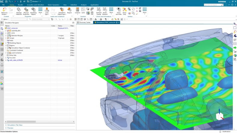
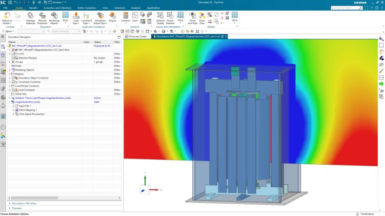
The latest version of Simcenter 3D software includes enhancements for low- and high-frequency electromagnetic solutions to help accelerate electromagnetics simulation processes. This version advances simulation capabilities with increased multidisciplinary integration capabilities, faster CAE process, increased openness and scalability, and enhanced capabilities to integrate with the digital thread.

Including electromagnetic simulation into Simcenter 3D enables engineers to perform electromagnetic simulation faster than with traditional simulation tools and streamline multiphysics workflows between electromagnetic and other physical simulations.

Additional enhancements to Simcenter 3D include:
• Faster CAE Processes: A new immersed boundary method helps engineers spend less time modeling for computational fluid dynamics (CFD) analysis. Engineers can also instantaneously compute new configurations for flexible hoses and pipes after a design configuration change.
• Open and Scalable Environment: Engineers can use calculated vibrations from common third-party finite element (FE) solvers, ANSYS and Abaqus, and apply those vibrations as loading in a structural or vibro-acoustic solution in Simcenter 3D, which can lead to a better understanding of how vibrations will impact perceived sound by end-customers.
• Tied to the Digital Thread: An enhanced interface between Simcenter 3D and Simcenter Testlab software helps engineers better collaborate with colleagues in the test group. New capabilities available in Teamcenter Simulation help engineers quickly identify which simulations are impacted after a design change.

Siemens Digital Industries Software
new.siemens.com/global/en/

Filed Under: Siemens PLM, Simulation Software Tagged With: Siemensdigitalindustriessoftware

More features for Solid Edge 2020, including augmented reality

June 10, 2019 By Leslie Langnau Leave a Comment

The latest version of Solid Edge software has many enhancements, including augmented reality, expanded validation tools, model-based definition and 2D Nesting. Solid Edge 2020 provides next generation technologies to enhance collaboration and fully digitalize the design-to-manufacturing process.

Solid Edge 2020 delivers augmented reality capabilities that enable users to visualize design intent in new ways, enabling enhanced collaboration internally, as well as with suppliers and customers during the design process. New validation tools have been integrated for conducting motion and vibration simulation, which can help customers reduce costly prototypes. The addition of Model Based Definition enables users to completely define parts, assemblies and manufacturing instruction digitally from their 3D model. 2D Nesting capabilities have also been added to optimize cutting patterns, reduce waste and costs, and accelerate manufacturing processes. Solid Edge 2020 also delivers hundreds of core CAD enhancements such as new sheet metal capabilities, 3-10x faster large assembly performance, new data migration tools, and others across the portfolio.

Siemens Digital Industries Software
www.siemens.com/plm

Filed Under: Simulation Software Tagged With: Siemensdigitalindustriessoftware

Altair releases HyperWorks 2019, unifying design, engineering, and manufacturing

June 10, 2019 By Leslie Langnau Leave a Comment

Altair, a global technology company providing solutions in product development, high-performance computing and data intelligence, announced the release of Altair HyperWorks 2019, the latest version of its simulation- and AI-driven product development platform. The release expands on the number of solutions available for designers and engineers, under a single, open-architecture platform, to speed decision-making and time to market.
“We want to help our customers explore more ideas, better understand their designs, and improve profitability,” said James Scapa, Altair’s chief executive officer and founder. “Our development focus for HyperWorks 2019 was to increase the solve speed and functionality across our solutions for every stage of product development with optimization and multi-physics workflows for all manufacturing methods.”

Highlights of this release include:

Fast simulation of complex assemblies
Altair SimSolid makes designers and engineers more productive by performing structural analysis on original, un-simplified CAD assemblies in seconds to minutes. SimSolid can analyze complex parts and large assemblies that would take hours or days using traditional structural simulation tools.

Easy-to-learn fatigue life prediction
Altair HyperLife enables customers to quickly understand potential durability issues through an easy-to-learn solution for fatigue life under static, transient and vibrational loading. The intuitive user experience enables test engineers to perform simulations with little or no training. HyperLife helps customers to confidently predict product durability in hours, complementing physical testing, which can take months.

Efficient workflows for multi-physics
Altair SimLab is an intuitive workflow platform for simulating multi-physics problems. Automatic feature and part recognition can make simulation cycles more than five times faster. Design exploration is easier with synching to popular CAD tools. The multi-physics workflows feature deeply embedded solvers; including statics, dynamics, heat transfer, fluid flow, electromagnetics analysis, fluid-structure interaction, and electromagnetic-thermal coupling.

Superior high-fidelity modeling
HyperWorks 2019 includes the most robust Altair HyperMesh version yet. New features enable the generation of the largest, most complex finite element models. The model build and assembly tools in HyperMesh make managing large, complex assemblies easier than ever. This allows CAE to keep pace with design changes by rapidly swapping new parts and assemblies into existing models, managing multiple configurations, mesh variants and part instances. The direct mid-mesh generation makes it possible to create shell meshes straight from solid geometry of complex castings and injection molded parts.

Enhanced user experience for fast concept modeling
The HyperWorks platform already includes Altair Inspire, Altair Activate and SimLab delivering class-leading solutions with intuitive and consistent user-interfaces. In this release Altair HyperWorks X is included with a new set of workflows for geometry creation, editing, morphing and meshing employing this same user experience. The easy-to-learn mesh morphing features of HyperWorks X will bring efficiency to teams working on simulation models early in product development. These workflows enable concept level changes to be made directly on an existing FEA model bypassing CAD generation and accelerating decision-making.

Expanded non-linear solver functionality
Analysis with Altair OptiStruct is increasing at companies performing stiffness, strength and fatigue-life simulations; fueled by the significant process improvement it provides. The single-model, multi-attribute workflow enabled by OptiStruct delivers time and cost savings. Design decisions can be made faster by engineers performing linear, non-linear, and durability analysis – using one optimization-ready model.

Altair
www.altair.com
altair.com/HW2019

Filed Under: Simulation Software Tagged With: Altair

MapleSim 2019 improves performance, increases modeling scope

May 23, 2019 By WTWH Editor Leave a Comment

Maplesoft announced a new release of MapleSim, the advanced system-level modeling tool. From digital twins for virtual commissioning to system-level models for complex engineering design projects, MapleSim helps organizations reduce development risk, lower costs, and enable innovation. The latest release provides improved performance, increased modeling scope, and more ways to connect to an existing toolchain.

Simulation is faster for all customers in MapleSim 2019 due to more efficient handling of constraints when preparing the model, resulting in more compact, faster simulation code without any loss of fidelity. These results mean that MapleSim’s industry-leading speeds have gotten even better, saving time and enabling more real-time applications. In addition, models developed in MapleSim and then exported for use in other tools also run faster in the target applications.

New built-in and add-on components and expanded support for external libraries means that engineers can create more models, faster, in MapleSim 2019. The new release expands the scope of models that can be created using pre-existing components, with additions to hydraulics, electrical, multibody, and more. As well, the MapleSim Engine Dynamics Library from Modelon is a new add-on library that provides specialized tools for modeling, simulating, and analyzing the performance of combustion engines. This component library is especially useful for representing transient engine responses, and can be used for analyzing engine performance, performing emission studies, controls development, hardware-in-the-loop verification of vehicle electronic control units, and more.

Toolchain connectivity is essential to many MapleSim customers, and MapleSim 2019 offers important advances in toolchain integration. Improvements include additional options for FMI connectivity, including support for variable-step solvers, as well as fixed-step, for running imported models in MapleSim and exporting models to other tools. In addition, the new B&R MapleSim Connector add-on gives automation projects a powerful, model-based ability to test and visualize control strategies from within B&R Automation Studio, and to export simulation data for motor, servo, and gearbox sizing within SERVOsoft®.

“System level modeling has proven to be an invaluable tool for companies embarking on challenging engineering design projects, especially in the areas of automation and the creation of digital twins. Models can be used to both verify a design, as well as act as a virtual test bench for the machine’s control software – all before prototypes are built,” said Chad Schmitke, Senior Director, Product Development, Maplesoft. “Whether an organization wishes to develop their own models or work in partnership with the Maplesoft Engineering Solutions team, the improvements in performance, scope, and connectivity in MapleSim 2019 offer benefits to everyone.”

MapleSim is available in English, Japanese, and French.

Maplesoft
www.maplesoft.com

Filed Under: Simulation Software Tagged With: Maplesoft

Simulation On-The-Go with COMSOL Client for Android

April 25, 2019 By Leslie Langnau Leave a Comment

COMSOL announces that COMSOL Client for Android is  available. Researchers, engineers, and students can perform simulation tasks from their Android devices, such as phones, tablets, and Chromebooks simply by connecting to the COMSOL Server software which runs the computations remotely.

COMSOL Client for Android expands on the capabilities of the Application Builder and COMSOL Server by enabling you to take your simulation applications on the road, without being limited by your device hardware. Providing field technicians or sales representatives with the power of COMSOL Multiphysics directly on their Android devices allows them to bring the R&D work on site or to the sales pitch.

“COMSOL Server allows users to run simulations through web browsers or desktop-installed clients,” explains Daniel Ericsson, Applications Product Manager, COMSOL. “COMSOL Client for Android expands on those capabilities by introducing a more seamless user experience on Android devices.”

“Using COMSOL Multiphysics and its Application Builder I can create models and build apps based on them. This allows other departments to test different configurations for their particular requirements and pick the best design,” comments Sam Parler, Research Director at Cornell Dubilier.

The Application Builder and COMSOL Server were developed to make multiphysics modeling more accessible to a wider audience. The Application Builder allows simulation specialists to create custom-made applications based on their multiphysics models. With COMSOL Server, organizations have been able to deploy industry-specific analysis tools in a streamlined and quick to implement format that can be scaled for global benefit. COMSOL Client for Android has made the convenience of running simulation applications as easy as ordering a rideshare.

Just like COMSOL Client for Windows, the simulations are run on remote servers, so you are not limited by your device hardware. Administrators continue to have full control over who can access and run the apps by using COMSOL Server. Android users will have the latest version of a simulation application each time they open the app.

COMSOL
play.google.com/store/apps/details?id=com.comsol.androidclient

Filed Under: Simulation Software Tagged With: COMSOL

  • Go to page 1
  • Go to page 2
  • Go to page 3
  • Interim pages omitted …
  • Go to page 23
  • Go to Next Page »

Primary Sidebar


3D CAD NEWSLETTERS

MakePartsFast

Follow us on Twitter

Tweets by 3DCADWorld

Footer

3D CAD World logo

DESIGN WORLD NETWORK

Design World Online
The Robot Report
Coupling Tips
Motion Control Tips
Linear Motion Tips
Bearing Tips

3D CAD WORLD

  • Subscribe to our newsletter
  • Advertise with us
  • Contact us
Follow us on Twitter@3DCADWorld
Add us on FacebookDesign World Network
Add us on LinkedInLinkedIn
Add us on InstagramInstagram
Add us on YouTubeYouTube

3D CAD World - Copyright © 2019 · WTWH Media LLC and its licensors. All rights reserved.
The material on this site may not be reproduced, distributed, transmitted, cached or otherwise used, except with the prior written permission of WTWH Media.

Privacy Policy