• Skip to primary navigation
  • Skip to main content
  • Skip to primary sidebar
  • Skip to footer

3D CAD World

Over 50,000 3D CAD Tips & Tutorials. 3D CAD News by applications and CAD industry news.

  • 3D CAD Package Tips
    • Alibre
    • Autodesk
    • Catia
    • Creo
    • Inventor
    • Onshape
    • Pro/Engineer
    • Siemens PLM
    • SolidWorks
    • SpaceClaim
  • CAD Hardware
  • CAD Industry News
    • Company News
      • Autodesk News
      • Catia News & Events
      • PTC News
      • Siemens PLM & Events
      • SolidWorks News & Events
      • SpaceClaim News
    • Rapid Prototyping
    • Simulation Software
  • Prototype Parts
  • User Forums
    • MCAD Central
    • 3D CAD Forums
    • Engineering Exchange
  • CAD Resources
    • 3D CAD Models
  • Videos

Software

Found Faster: How searchable databases speed CAD design

June 18, 2020 By Leslie Langnau Leave a Comment

Searchable databases do away engineers’ need to recreate CAD files. As for importing models, CAD translators keep costs down.

Jean Thilmany, Senior Editor

Engineers spend nearly two hours each day searching for or recreating parts that already exist, according to a survey done by Cadenas PartSolutions, a Cincinnati maker of parts management software. That number represents a significant loss of time engineers could otherwise be spending on more valuable projects.

By doing away with the need to search or recreate, engineers could get back those 1.8 hours each day: an obvious financial win. The key is to give engineers an easy way to find already-existing CAD models that can be dropped into assemblies. That way, they don’t have to recreate the wheel each time they design. If a company can standardize and reuse simple parts like fasteners, it can save a huge number of engineering hours.

But part reuse can be difficult if locating designs is a problem to begin with. How can engineers know if the CAD design for a part already exists if they don’t know where, or how, to begin looking?

The answer is a searchable database. In the past, these types of parts libraries were the purview of large companies with many decentralized parts databases that sprawled across divisions. But within the past decade or so, the search technology has increasingly become available to companies of all sizes.

In 2013, IBM implemented what it called a strategy for the reuse of assets.

“Developing an orchestrated process to maximize the reuse of assets across the product lifecycle increases design efficiencies and tames product complexity,” according to the 2014 IBM article “Strategic reuse and product line engineering” authored by Eran Gery, IBM distinguished engineer, and Joanne Scouler, IBM curriculum architect.

Companies that make products like vehicles, medical devices, and consumer electronics make multiple products that share common elements, which results in “product lines” or “product families.” Reuse of assets across a product line or family is a major efficiency improvement for easing product design pressures, the authors say.

In the article, they outline the reuse system IBM has put into place, which is built upon the company’s IBM Rational systems and software engineering platform.

The company found that without a part-reuse system, companies:
• Waste time and money developing components that already exist in other company products.
• Needlessly change and recreate assets that already exist.
• Compromise product quality by following an error-prone manual process.
• Make needless changes to existing assets.

While IBM was able to implement its program on its own software engineering platform, other companies don’t have a home-grown platform in place. They can, however, use third-party applications to create searchable parts libraries that help do away with needless part recreation.

For example, Parker-Hannifin, the maker of motion and control systems, recently implemented Cadenas Part Strategic Part Management software to streamline the reuse of 3D parts across several of the company’s divisions. The software is comprised of a searchable, centralized database of 3D parts and data that engineers use to find the component they need. They can search based on part geometry, topology, text, sketch, or dimensions.

The project’s payoff is the capability to reuse internal components across all Parker divisions and in the reduction in time spent finding parts, says Tim Thomas, Cadenas PARTsolutions chief executive officer.

All Parker-Hannifin’s divisions were brought onto the common parts management system, which included an enterprise part-numbering strategy, he adds.

Going Up? Coming Together
When a company grows by acquiring other companies, it often must fold in different IT and CAD environments along with the purchases. Because those systems don’t “talk” to one another, they prevent engineers from finding all parts that exist in the company’s CAD systems. This is another way a centralized database hastens CAD file reuse.

Take the example of The Wittur Group, a German company that makes a range of elevator components that include gearless drives, slings, safety gears, cars, and braking systems. Customers are global elevator installers including Kone, Otis, Schindler, and Hitachi as well as smaller, independent installers.

Through the years, as Wittur grew to become an international company, it brought newly acquired businesses’ IT systems onboard as well. It also maintained the acquired company’s CAD files of existing parts, says Markus Aichinger, corporate CAD manager at Wittur.

Soon, the company’s diverse CAD environments prevented engineers from easily finding those parts, he adds. Data was stored in different legacy databases, each with its own material codes, norms, and structure, which had to be sifted through individually, he says.

Not surprisingly, the process of discovering whether a CAD part already existed or needed to be redesigned took a lot of time.

In addition to making the search process easier, Wittur also wanted to reduce the number of duplicate parts to avoid confusion, Aichinger says.  “Our engineers were having difficulty finding existing parts for new projects, so they preferred redesigning them, even though, in many cases, a similar part existed. The continuous duplication of parts also required additional storage space.”

In addition to time spent designing a new part, engineers also spent time prototyping and testing the part, adding further costs, he adds.

Wittur officials at the company knew what they needed: a searchable system that linked company databases and eliminated duplicate parts.

“This system would help us find existing parts for reuse in new projects and provide global users with a single point of entry to find up-to-date production drawing information,” Aichinger says.

To search 3-D CAD geometry, Wittur implemented the Exalead OnePart application from Dassault Systèmes. The system includes a shape-search feature, which locates parts that match the original shape and also displays close-matches in the search results. The tool identifies master parts for reuse to ensure engineers select the preferred part without recreating a part that already exists in the design library, says Gian Paolo Bassi, chief executive officer at Dassault Systèmes SolidWorks.

To find 2-D drawings, the elevator-parts supplier created a drawing information system that runs on the Exalead platform.

“We’re not only able to find the 2-D drawings themselves, but all the metadata—part tolerances, material information, and where drawings are used— associated with each drawing. We can also display a component’s design history and show the latest revisions,” Aichinger says. “Before we had this, our engineers would have to search for this information in different sources.”

Bassi calls Exalead OnePart a “borderline artificially intelligent product” because it recognizes and flags part similarities, he says.

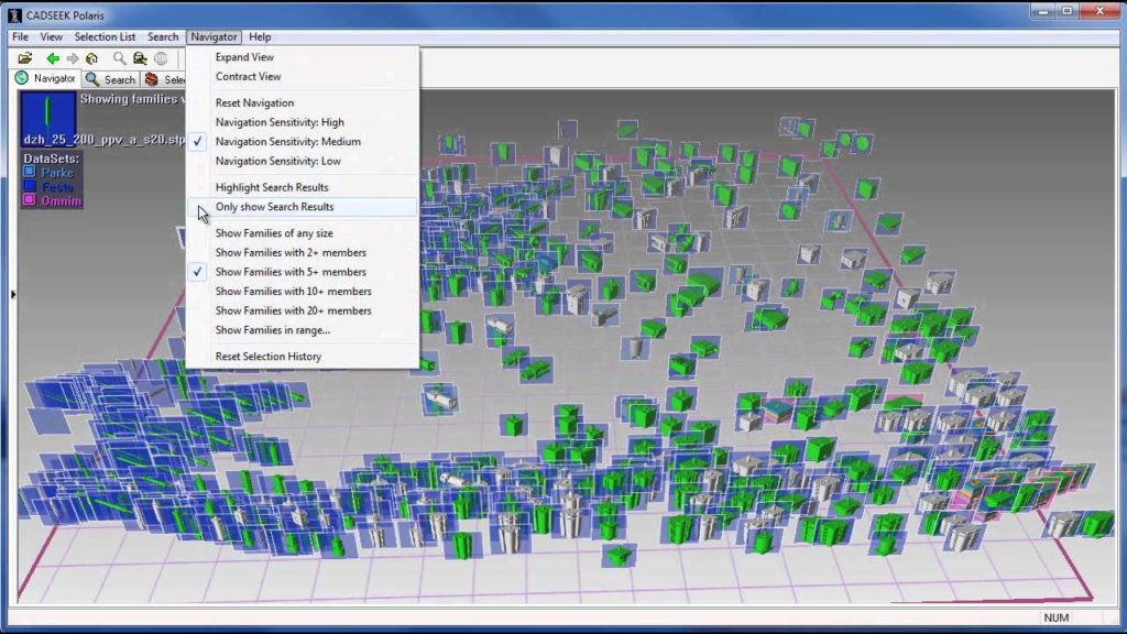
When an engineer finds a particular part within the CADSeek Polaris system, they also find other information associated with the part, including cost, supplier names, manufacturing information, and analysis results, says Rick Mihelic, a former engineering systems manager at Peterbilt Motors, which stores searchable part information on the CADSeek Polaris platform from iSeek of Ames, Iowa.

CADSeek searching parts to find matches

The tool locates existing parts and assemblies using shape alone, text-based attributes alone, or a combination of the two. It also identifies duplicate parts, which allows for cost savings through parts consolidation, standardization, and part-number reduction, Mihelic says.

Typically, CAD models are only classified based on text-based attributes, which are rarely complete or uniformly applied. But even if attributes could be complete and uniform, two items labeled as “valves” can be so different that applying analytics is a waste of time. With the CADSeek system, each time an engineer searches a dataset, such as valves, they can apply similarity thresholds. For instance, an engineer might ask the system to show all models with at least 91% or greater similarity to the valve used for the search, says Abir Qamhiyah, iSeek Corp’s chief executive officer.

But engineers aren’t company employees that reuse CAD parts. For other personnel, who aren’t always at their desktops, iSeek recently introduced CADSeek Mobile, that lets users take 2-D photos of parts on their Android, IOS or Windows mobile device and to use those images to automatically search their company’s 3-D CAD databases for the piece pictures or for a similarly shaped part.

Manufacturers like Moen and Embraer use iSeek’s original shape-based search application, CADSeek Polaris. At those companies, designers and supply chain personnel use the application to find CAD data for part reuse, to standardization opportunities, for vendor price analysis, should-cost estimation, automated quotations, mergers and acquisitions, and for data cleanup and consolidation, Qamhiyah says.

Small parts in particular often lose their identifying numbers, no matter whether that inventory is housed in an assembly plant, distribution center or out in the field. When those vital identifying numbers disappear and parts can’t be easily reordered, perfectly good parts are scrapped or time is wasted, he adds.

Getting the Design Inside
Now let’s take the opposite problem: how to best bring a CAD design into a system so that it can be used to create a part.

a CAD assembly and part on the Hoops CAD translation platform from TechSoft

The additive manufacturing industry needs to get manufacturing data into their systems. It’s traditionally used stereolithography files, though they can be error prone, says Gavin Bridgeman, CTO at TechSoft 3D, which makes CAD translation software. By directly reading both native and standard CAD file formats, products can increase their ease-of-use and ultimately their print quality.

Techsoft 3D’s Hoops Exchange toolkit does this for engineering-specific applications including many in the 3D printing market, he says. “We’ve seen a lot of growth recently related to people creating new software to solve problems in engineering data markets that didn’t exist a few years ago, like additive manufacturing service bureaus,” Bridgeman says.

The bureaus import 3-D CAD data from creators, use HOOPS Exchange to translate those files, and then print from them.

“People can put more manufacturing information into their 3-D files, but they also know how they want something to look visually,” Bridgeman says. “Service bureaus have to meet both manufacturing and visual needs.”

Whether an engineer wants to find a CAD model within a huge system or needs to import a model to create a 3-D printed part, search and translate technologies step in to slash engineering costs.

Cadenas PartSolutions
partsolutions.com

Dassault Systèmes
www.3ds.com

iSeek
www.iseek.com

TechSoft 3D
www.techsoft3d.com

Filed Under: Dassault Systemes, Software Tagged With: Cadenas, Dassault Systemes, iseek, techsoft3d

CAD and AI: making design better, faster, and easier

September 3, 2019 By Leslie Langnau Leave a Comment

AI has the potential to allow engineers to design products faster than before while meeting design specifications, sometimes in new and unique ways.

Jean Thilmany, Senior Editor

Artificial intelligence could be said to be the new hot buzzword, as it seems to be making inroads into all types of software.

“We don’t see a lot of AI yet in a CAD environment, but it’s coming,” says Andreas Vlahinos, chief technology officer Advanced Engineering Solutions, a research and design firm in Castle Rock, Colo.

AI is a broad field focused on using computers to do things that require human-level intelligence.

But how CAD will make future use of AI is still up for debate, he adds.

While some CAD makers are delving into AI functionality, the marriage of AI and design software is in the early stages, says Jon Hirschtick, chief executive officer of Onshape, which makes cloud-based CAD software.   “AI has great potential, but so far no one has illustrated how it will unfold,” he says.

AI doesn’t have a one-size-fits-all definition within any industry yet, says said Gian Paolo Bassi, chief executive officer at Dassault Systèmes.  “Today, there’s a huge debate about what AI is. People say AI is machine learning, or they say it’s related to the neural network or to neuroscience. Definitions vary.”

The machine learning that AI depends on is actually already present to a certain degree in the CAD systems that include topology optimization and generative design capabilities. “The primary functions of these features within CAD is to automate the analytical steps of design, Vlahinos says. The computer generates designs from an engineer’s preliminary directions.”

The key focus of AI in CAD right now is design optimization achieved through the creation of more intelligent designs which are lighter, stronger and more economical. And, in some cases, more artistic, continues Vlahinos.

Typically, designers create their design step by step, analyzing certain junctions to get critical feedback about performance. They tweak the design if it doesn’t meet performance needs or customer specifications. The incorporation of AI, as it stands now, allows the designers to skip these time-consuming steps allowing the task to get over quickly and effectively.

Last year, for example, Autodesk released generative design to subscribers of its Fusion 360 Ultimate product development software. The design concept allows engineers to define design parameters such as material, size, weight, strength, manufacturing methods, and cost constraints–before they begin to design. Then, using artificial-intelligence-based algorithms, the software presents an array of design options that meet the predetermined criteria, says Ravi Akella, who headed the product management team for Autodesk’s generative manufacturing solutions before moving last year to become director of product development at Roblox.  The feature focuses on helping designers define the problem they’re trying to solve, he says.

“The software asks the user preliminary questions. ‘What sorts of materials would you consider for your design? Where does it connect with other things as part of an assembly? What are the loads? What are the pieces of geometry?’” Akella says.

After a short period of time, the software then presents designers and engineers with an array of design options that best meet their requirements. Designers choose the best design. Or, if none of the options meet their needs, they can begin the generative process again, this time offering slightly different inputs.

Like other big-name CAD makers, SolidWorks also includes topology optimization capabilities within its CAD software.

“We expect the computing platform to anticipate your design goals,” says Bassi.

But, Vlahinos adds, the AI in those systems is used for simulation rather than for design. It’s by continual simulation that the designs are found. The tools allow the engineer to skip all the step-by-step analyzing. The human is still involved in the process and must validate the simulation the CAD system returns.

“The generative process could get you plus or minus 15 percent of the real answer but with 2 percent of the effort,” he says. “So, you know how to make the heat exchanger this way or that way – you’ve isolated the design alternatives and you can find them right away and validate.”

Even though the tools function through simulation, “You get amazing design insights and design innovation so you can see how something can be done,” he says.

But Vlahinos cautions against relying fully on the current AI-enabled CAD optimization tools.

“They are not simulation replacement,” he says. “Don’t let the vendors oversell them. They are design guidance, like a spell checker for you design concept. But they do give you more amazing results.”

Still, by helping engineers more quickly meet their prescribed design specifications, AI also frees up time engineers can spend focusing on other aspects of the piece—like its inherent shape or its artistic merits.

And – with proper validation in place — these tools can help ensure parts will meet manufacturing specifications and allow for much quicker design than traditional methods. It also can create unorthodox, sometimes never-before-seen-shapes that can be manufactured through 3D printing.

 The engineer as artist

Design for manufacturability, as it’s called, is of course an important—some might say bedrock—necessity. AI techniques have a role to play in other aspects of design. And some of its uses may not have been conceived of yet, as CAD makers focus on these first AI implementations, Vlahinos says.

“Right now, it’s ‘Please tell me what the optimal shape is to achieve my engineering goal,” Vlahinos says. “We could see AI answering other questions in the future.”

Though his career has focused on rapid product development — Vlahinos recognizes that AI could help engineers design products faster than before — at the same time it offers engineering company customers new and unique ways to meet needs they may not even know they have.

For instance, broaden the view beyond the focus on manufacturability and AI can also lend artistic value to an engineered piece or product, he says.

“We’ve never properly valued the artistry of the design. But we could,” he says.

A product’s design artistry is, of course, subjective, so putting a monetary value to that number — as opposed to function — has always been elusive. Likewise, the capability to add never-before-seen geometries that create swirls and whorls in new and unexpected ways to pieces can bring a great deal of satisfaction, or headaches, for designers, depending on their liking to bring creativity to their engineering work.

With proper validation in place — AI tools can help ensure parts will meet manufacturing specifications and allow for quicker design than traditional methods. It also can create unorthodox, sometimes never-before-seen-shapes that can be manufactured through 3D printing.

If CAD can evolve, in the not-too-distant future, everyday objects like your blender, electric toothbrush or even the engine within your automobile, will take the shape of nothing you’ve ever seen before, said Hod Lipson, a mechanical engineering professor Columbia University and director of the school’s Creative Machines Lab. He is a roboticist who works in the areas of AI and digital manufacturing.

Most 3D printers take their printing instructions from 3D CAD files. Because the 3D printer receives its instructions from CAD files, the printers are limited in the shapes that those CAD systems generate, Lipson says.  CAD software only allows for designers to work with recognized geometries: circles and ovals, squares and rectangles, and so on, he says.

That’s changing as topology optimization and generative design capabilities make their way into design tools, Vlahinos adds.

So the day of the twisted blender may be upon us sooner than we think.

Beyond simulation

Feature and character recognition, which have been part of AI for many years, are part of the SolidWorks system. In fact, they’re so standard that many users may not recognize the AI component of those features—until, for instance, they begin to type a misspelled word they use frequently and see that word corrected automatically, Bassi says.

And AI has a role in CAM as well. For instance, SolidWorks CAM automatically generates a part’s manufacturing toolpath after design. CAM software uses the CAD models to generate the toolpaths that drive computer numerically controlled manufacturing machines. Engineers and designers who use CAM can evaluate designs earlier in the design process to ensure that they can be manufactured, Bassi says.

AI has a role in CAM as well as CAD. For instance, SolidWorks CAM automatically generates a part’s manufacturing toolpath after design. CAM software uses the CAD models to generate the toolpaths that drive computer numerically controlled manufacturing machines. Such a features helps engineers evaluate designs earlier in the design process to ensure that they can be manufactured.

“The toolpath captures design strategies and recognizes features and types of materials, so you can have a CAM solution that’s almost completely automated,” Bassi says. AI drives the way the toolpath is automatically created.

“You can create a toolpath in a couple of clicks. You don’t need a lot of details for intelligent manufacturing,” Bassi said.

One thing is certain, Vlahinos says. AI will never take the human engineer or designer out of the equation.

Even intelligent machines need guidance. That means engineers will always be vital to the design process, he adds. A human will always be needed to view shapes and designs in the same way other humans will. To translate a part’s use, — its form, and its function — with an eye toward other human users.

Filed Under: AI, Software

Mazda uses Siemens generative engineering tools to drive creativity

July 23, 2019 By Leslie Langnau Leave a Comment

Siemens announced that Mazda Motor Corporation adopted the Capital electrical design software suite from Mentor, a Siemens business, to help maximize innovation in the design of next-generation automotive electrical systems. Recognized worldwide for its successful launch of innumerable innovative technologies, Mazda uses Capital for model-based generative design for the electrical and electronic systems of the entire vehicle platform. The Capital automated generative design flow helps Mazda automotive design teams manage design complexity and changes across the entire vehicle platform, minimizing errors and reducing costs.

The Capital electrical design software suite can help Mazda optimize vehicle development by creating a seamless development environment, helping manage the complex designs required for the future of mobility.

The development of safe and efficient electrical designs has become a critical task as the automotive industry moves towards large scale system developments such as electrified powertrains and autonomous driving. These designs are often based on entirely new architectures and have become so complex that advanced software tools are needed to enable development efforts. Capital tools deliver real time feedback against target metrics such as cost, weight, and network bandwidth consumption. This allows engineers to explore alternative design approaches, which is extremely important for large scale system developments represented by electric and autonomous vehicles. Capital software also provides Mazda with extensive simulation and verification functionalities.

At Mazda, from system design, harness design and verification down to manufacturing and service documentation, outputs of each process have been generated in its natural language, requiring designers to translate between processes and fill in the missing pieces using their talents and skills. “In order to remove ambiguity while maintaining the diversity of expressions that are characteristics of these natural languages, we applied formal methods to eliminate the loss in information transfer and set a goal to build a development environment that is consistent and connected all the way through the manufacturing phase,” said Kazuichi Fujisaka, Technical Leader, Mazda Motor Corporation. “Furthermore, we also aim to shift to a development methodology that allows us to optimize the vehicle as a whole, with all possible variations being considered in the early development stage. To make this happen, we needed a development environment to visualize the entire vehicle circuitry and standardize our language, tools, and processes without compromise, creating standard models across the company. Mentor’s Capital technologies provide this environment and make Mazda’s electric development much more efficient.”

“One who keeps challenging what seems impossible leads innovation – a fact Mazda clearly understands, as evidenced by its long history of innovation,” said Martin O’Brien, senior vice president, Integrated Electrical Systems, Siemens Digital Industries Software. “As a long-standing Capital customer, Mazda has proven to be a fast adopter of new capabilities, such as platform-level architecture optimization spanning the electrical, electronic, networking, and embedded software disciplines. As a growing number of Japanese automotive OEMs adopt Capital, Mazda has established its reputation as a forward-thinking early adopter, with a long track record of leveraging our sophisticated technologies from their ‘customer first’ point of view.”

In addition to the Capital Electrical Design Software suite, Mazda also uses Siemens’ NX software and Teamcenter portfolio for enterprise collaboration.

Siemens Digital Industries Software
www.siemens.com/plm

Filed Under: Software Tagged With: Siemensdigitalindustriessoftware

What’s driving the automotive lightweighting revolution?

April 26, 2019 By WTWH Editor Leave a Comment

A perfect storm of social and regulatory changes, AI-driven generative design, and advances in additive manufacturing are bringing automotive lightweighting into the mainstream.

By Avi Reichental, CEO, Techniplas Digital

Since the widespread adoption of industrial technology began in the late 18th century, there have been only a handful of instances where a combination of social change, technological advancement and public policy converged to create the perfect environment to precipitate exponential change.

Today, we are witnessing just such a perfect storm in automotive lightweighting. The result will be a fundamental change in the way people and goods move from one place to another.

What exactly is driving the automotive lightweighting revolution, and how will its effects continue to emerge? To understand this, we need to take a deep dive into both the technological and social/regulatory sides of the equation.

Social and regulatory changes drive demand, but efficiency drives change
Environmental concerns like global warming are driving governments worldwide to demand changes from carmakers with strict emissions and fuel efficiency standards. In addition, consumers are beginning to take vehicle efficiency into account, and manufacturers are being forced to adapt.

But pure vehicle weight considerations are not the primary driving force behind the move to lightweighting. Manufacturers are prioritizing not only vehicular efficiency (of which weight is a key factor), but also overall manufacturing and operational efficiency.

Thus, social and regulatory demands have moved the ball into the manufacturing court. Yet what’s truly driving the lightweighting revolution and making it economically and ecologically viable to lightweight on a massive scale is the technological revolution that’s enabling the design and at-scale production of lightweighted parts.

AI-driven generative design is transformational
AI-driven generative design is lightweighting’s secret sauce.

The reason? Lightweighting by definition relies on either material substitution or reduction – achieving the same function with the same amount of a lighter material or less material. We’ve essentially reached the cost-benefit breaking point for material substitution, and thus the automotive industry has turned to material reduction for lightweighting. And material reduction is where AI-driven generative design truly shines.

AI-driven generative design transforms CAD from an electronic drawing board to a co-designer. Novel solutions created via generative design have shattered existing design paradigms, making the production of organically inspired structures – which can optimize materials usage and radically lower weight without compromising integrity – a reality.

Additive manufacturing brings generative design to life
Without the ability to produce amazing AI-driven designs at scale, the lightweighting revolution would be stuck in the laboratory. Thus, the final element of this “perfect lightweighting storm” is Additive Manufacturing (AM). Today, the automotive industry has the capability, tools, and experience to produce the complex and lightweight geometries created by generative design cost-effectively, rapidly, and at scale.

AM enables vehicle manufacturers to produce millions of the same parts or millions of one-of-a-kind parts. This turns conventional manufacturing wisdom on its head and provides automotive manufacturers a new degree of freedom that it has not previously experienced.

So where does lightweighting come in? The fact is that the components being created by generative design can only be practically manufactured using additive techniques.

Thus, the next generation of lightweighting is tied intrinsically to AM. And this is where things get fascinating. Because now, generative designs are being optimized for AM. Complex geometry is no longer a limitation, but an enabler. Tooling is no longer a must, and more parts can be combined into homogenous units at the design stage, without assembly – lowering part count and (you guessed it) weight.

The bottom line
Automotive manufacturers were early AM adopters – using it for design and prototyping for decades. They realized that this technology was a game changer, yet material performance, computing power and scalability were holding them back.

Today, processes are more cost effective, more scalable, and development cycles are shorter. Today, 3D-printed parts are being produced on a mass scale, and the foundation of traditional manufacturing is being rocked. With the addition of powerful and effective AI-driven generative design, automotive lightweighting today is limited less by technology than by pure imagination.

Filed Under: CAE, CAM, Make Parts Fast, Software Tagged With: techniplasdigital

Updates in CAD focus on better simulation

April 19, 2019 By Leslie Langnau Leave a Comment

While the latest upgrades to major CAD systems don’t make major changes to the way those programs operate, they do include significant updates. Here’s a look at some of the biggest enhancements and key features of these programs.

Jean Thilmany, Senior Editor

CAD packages continue to see regular updates, whether a major release, or the minor updates that happen throughout the year. Some updates include major enhancements or new features, as is the case with NX, which now includes machine learning and artificial intelligence features. The company will quit bringing out yearly NX updates, as the software is now offered on continuous release.

Other popular programs like Creo, Solid Edge, SolidWorks, and Autodesk Fusion 360 have seen changes as well. More than one company has changed the way in which they name the new versions of their software and several boast new or enhanced simulation capabilities.

Here’s a look at the most recent updates.

NX from Siemens PLM

In February, Siemens announced an update to its NX CAD software, which now includes machine learning and artificial intelligence features that, by following users’ patterns over time, come to automatically predict their next steps and anticipate their needs.

The programs do this by monitoring the actions of the user and following their success and failures. In that way, the features determine how to serve up the right NX commands and also modify the user interface accordingly, says Bob Haubrock, senior vice President, product engineering software at Siemens PLM Software.

Machine learning is increasingly used in the product design process because it has the power to process, analyze, and learn from large volumes of data, he adds. In this way, designers can more efficiently use software to increase productivity. The ability to automatically adapt the user interface to meet the needs of different types of users in various departments can increase CAD adoption rates at a company, continues Haubrock.

In another recent change, Siemens PLM Software began delivering NX using a continuous release model. This means the software updates are produced in short cycles and are released when needed, at any time.

The model gives NX users faster access to new enhancements and quality improvements, while reducing the efforts needed to effectively deploy NX, Haubrock says. “With automatic updates, customers do not have to search for updates online and will not miss critical fixes. The NX Update mechanism will automatically notify and install important updates as they become available.”

With continuous release, users can turn on “automatic updates” within their system to ensure they always receive the updates. The approach helps reduce the cost, time, and risk of delivering changes by allowing for more incremental updates to applications.

Thus, NX will no longer be identified by a release number and will only be referred to as NX. In other words, there will be no NX13.

The CADmaker says it’s the first major CAD, CAM, and analysis vendor to deliver its products in this way.
The company says the new approach will enable Siemens’ NX users to:
–Receive enhancements faster to help boost productivity
–Have a consistent schedule for updates
–Better plan for the adoption of new technologies
–Reduce deployment costs

Creo from PTC

In February PTC released Creo Simulation Live, which allows engineers to perform simulation in real time on their parametric models because ANSYS simulation capabilities have been integrated with the Creo CAD tool.

Creo Simulation Live, from PTC, lets engineers perform simulation in real time on their parametric models because ANSYS simulation capabilities have been integrated with the Creo CAD tool.

“Every time you make a change in your model, you’ll see the consequences instantaneously in the modeling environment,” says Brian Thompson, PTC senior vice president, CAD segment.

“The goal is to remove the barrier between the CAD and CAE world,” says Andrew Leedy, a PTC applications engineer. “This is targeted toward the engineer or designer rather than the analyst.”

The simulation software runs linear, structural, thermal, and modal analyses. The solver uses GPU rather than CPU for instantaneous analysis, Leedy adds. “So as soon as you make changes to the model it updates the graphics that drive the simulation.

The capability to simulate and design simultaneously helps engineers understand the implications of what they’re making, he adds.

The integrated tool also eliminates the need for the engineer to mesh the model before running a simulation and does away with the post-processing step.

The integrated simulation software from ANSYS is called Discovery Live.

“Engineers can ask ‘What if I add this hole, what will it do to the model?’” he said. “This works on top of the model, it works directly within the environment an engineer is used to.”

The CAD software does require a graphics card that supports the ANSYS tool.

Solid Edge from Siemens PLM

Solid Edge 2019 brings a new naming convention to the tool, which will now be referred to by the year in which it is released. This makes it easier for engineers to identify the release they’re using as well and to identify the products within the Solid Edge portfolio, says Ben Weisenberg, applications engineer at product lifecycle management company Prolim. Weisenberg frequently details Solid Edge updates to the CADmaker’s user community.

Solid Edge 2019, from Siemens PLM, makes it easier for engineers to identify the products within the Solid Edge portfolio. The most significant updates for mechanical designers are tools that allow engineers to model and simulate the entire production process along with the final product.

The most significant updates for mechanical designers are tools that allow engineers to model and simulate the entire production process along with the final product, Weisenberg says.

These include the convergent modeling tools that designers can use to integrate mesh models directly into their workflows. They can use these tools for the milling, casting, and molding of generative designs and 3D printed designs.

Manufacturing constraints allow engineers to optimize the weight and strength requirements of their model. A new design-for-cost feature shows the anticipated cost of the part, to help keep product development on track and within budget.

Updated simulation capabilities include:
–Enhanced structural and thermal simulation, including transient heat transfer.
–Time-based history analysis enables simulation of thermal and cooling performance.
–Free surface flow simulation, lighting and radiation capabilities allow digital “what if” analysis.
–The ability to display simulation results on geometry faces to help engineers make more informed judgments about the model.

SolidWorks from Dassault Systèmes

New features to the program, released in September 2018, let product development teams better manage large amounts of data and capture a more complete digital representation of a design. The program also offers new technologies and workflows that improve collaboration and enable immersive, interactive experiences during design and engineering.

SolidWorks 2019, from Dassault Systèmes, is powered by the company’s 3DExperience platform, which runs the CAD, simulation, and other tools on which designers and engineers rely. Those applications on the 3DExperience platform are tailored to SolidWorks users and mid-market companies.

Other new features include the capability for engineers to interrogate or rapidly make changes to a model through an enhanced large design review capability. Another upgrade gives teams a way to communicate with others not involved in design. With this feature, viewers of the CAD design can add markups to parts and assemblies and then export the marked-up designs as a PDF.

The most recent update from Dassault Systèmes involves the Works portfolio, which will bring applications like SolidWorks together with business solutions like a company’s enterprise resource planning (ERP) system. Typically, ERP systems track all pertinent companywide business processes, including accounting, supply chain, and human resources.

When parent company Dassault Systèmes launched SolidWorks 2019, executives stated that the CAD tool was “powered” by the company’s 3DExperience platform, which runs the CAD, simulation, and other tools on which designers and engineers rely.

Those applications continue to run on the company’s 3DExperience platform and are tailored to SolidWorks users and mid-market companies. They have been folded in the 3DExperienceWorks portfolio.

SolidWorks executives term the new portfolio a “business experience platform.” It provides software solutions for every organization within a company—from design to enterprise resource management, says Bernard Charlès, vice chairman and chief executive officer for Dassault Systèmes. “It’s a way for mid-market companies to tie all processes together, from design to manufacturing.”

Use of the applications across the platform should improve collaboration, manufacturing efficiency, and business agility, he added. Companies can accomplish their work using one cohesive digital innovation environment instead of using a complex series of point solutions that requires jumping between applications and interfaces, Charlès, says.

The software on the platform includes SolidWorks, analysis, simulation, manufacturing, and ERP applications. It is available on-premise and in the public or private cloud. The platform connects data and streamlines business and design processes by providing dashboard templates, managed services, access to industry-focused communities and user groups, and applications specific to a variety of job roles, Charlès says.

Autodesk

Like other CADmakers Autodesk has consolidated its design, simulation, and other computer-aided engineering capabilities in one product, Fusion 360, which is available as a cloud-based product. The product unifies design, engineering, and manufacturing into a single platform, according to Autodesk.

Fusion is a 3D modeling took that includes simulation, visualization, rendering, CAM, and other functions within a single interface. It also includes a 3D animation tool and 2D drawing tools. The product runs on both Windows and Macintosh systems.

In March, updates to that product included the capability to know when a teammate is working on your design at the same time to avoid doing work that will be over-ridden by another designer. When someone is working on the same design, an icon is displayed in the toolbar. By using a mouse to hover over the icon, a designer can see who is working on the same design. If one person makes a change to the design and saves it, the icon in the toolbar will change, letting the designer know that the design now has a newer version.

The toolbar has been updated to include quick access tools and documents tabs that line up with one another for more space on the design desktop.

Also new is a hole-tap tool called taper tapped, which allows designers to choose among a variety of thread types.

Autodesk also maintains its AutoCAD and Inventor CAD tools with no plans to immediately discontinue those products. Those two CAD systems usually see a new release in March of each year; though as of press time Autodesk hasn’t announced 2020 versions of AutoCAD or Inventor.

At Autodesk University in November 2018, Greg Fallon, vice president of business strategy at Autodesk, did announce updates to a collection of tools that work inside Inventor as well as a suite of specialized toolsets now available with AutoCAD.

Two years previously at Autodesk University 2016, company officials said they expect to maintain Inventor for another five to ten years and plan to continue updating it and enhancing functions. The Inventor emphasis will continue to be on industrial machinery design, officials said at that time.

While Inventor may be phased out in favor of Fusion 360, this has not been explicitly stated by Autodesk executives.

As ever, there are too many CAD packages to include in a single roundup. Other applications include IronCAD, TurboCAD, OnShape, Catia, and KeyCreator. All these will include new and updated features in future updates.

As designers and engineers know, when it comes to CAD software, the key phrase is, constant evolution.

Ansys
www.ansys.com

Autodesk
www.autodesk.com

Dassault Systèmes
www.3ds.com

PTC
www.ptc.com

Siemens PLM
www.plm.automation.siemens.com

Filed Under: Autodesk, Creo, Siemens PLM, Software, SolidWorks

Maple 2019’s data analysis capabilities identify biomarkers of several cancers

April 12, 2019 By Leslie Langnau Leave a Comment

The ability to leverage complex data as a strategic asset is becoming increasingly critical, but the current labor market has a shortage of resources in big data analytics. Companies are faced with several challenges related to the inadequate resources necessary to process data. A long-time Maple user and quantum mechanics researcher, Marvin Weinstein, refers to the problem of extracting meaning from large data sets as, “How do we find a needle in a multi-dimensional haystack, when we don’t know what a needle is, and we don’t know if there is a needle in the haystack?”

Dynamic Quantum Clustering (DQC) accomplishes this feat by creating a density map of data using DQC’s proprietary Maple library, and Maple 2019 visualization tools. The result of a DQC analysis is a Maple animation that provides a visual record of the complex computations going on behind the scene. According to Marvin, Maple animations have been a big part of DQC’s success because they reveal answers without the complex mathematics. He says that, “these animations sell our product because they leverage the human ability to spot patterns developing in time and space.”

With Maple’s prototyping abilities and customizable features, Marvin was able to get DQC up and running within a week. Marvin confesses that “whenever I can avoid having to do things [manually], I do so.” By using the DQC compiled library within Maple, it was possible for Quantum Insights to have a powerful GUI without having to build the interface from scratch. Marvin believes that time is often wasted with unnecessary coding and analysis tasks, and exploits many of the built-in features of Maple to save time drive his research forward.

The core of DQC is an algorithm that maps a problem of unsupervised clustering to a problem in quantum mechanics. It uses quantum evolution to identify correlated information and reveals the details of the process through a Maple animation. This animation typically reveals hidden and unexpected insights into complex data. Marvin asserts that the aim of DQC is to “let the data speak for itself.” The advantage of working without making assumptions or hypotheses, without cleaning the data, and without the need for expert knowledge means that DQC is a data exploration method that is faster, cheaper and more efficient than current methods.

One of DQC’s major accomplishments thus far has been the identification of several biomarkers strongly correlated with multiple cancers. According to Marvin, TCGA analysis was selected as the initial step towards cancer research because cancer is a problem that everyone understands to be a big deal, and “we’ve all lost people we love to cancer.” The hope was that better clustering methods would allow mRNA from various tumor samples to better classify tumors into biologically relevant groups. The study identified 48 of 73,000 mRNA expressions that defined all five different cancer types. This analysis, published in Nature Scientific Reports, has demonstrated the ability to provide an accurate diagnosis of cancer type, based on molecular information alone, and has further revealed significant sub-typing of cancer cells, beyond what pathologists can currently achieve. The sensitivity to variation in mRNA expression patterns is the “holy grail” of precision medicine, because it promises to tell us which tumors are likely to respond to a drug and which tumors will not respond. Moreover, the analysis showed that DQC significantly outperformed tSNE-HDBScan, the current gold standard clustering method used in cancer data analytics.

Now, Marvin is working in pharmacogenomics to offer better diagnosis and treatment methods for cancer and other diseases. His company, Quantum Insights, is working towards developing effective, data-driven strategies. While Quantum Insight’s initial focus was cancer, the goal is to expand this research into other healthcare applications. Marvin believes that the DQC technique will help save lives wherever better analytics are required. Other successful applications of his research include Alzheimer’s data, detection of contraband nuclear material, analysis of the Sloan Digital Sky Survey Data, and other areas that utilize large amounts of data.

Maplesoft
www.maplesoft.com

Filed Under: News, Software Tagged With: Maplesoft

Designed by engineers with nature’s help

March 29, 2019 By Leslie Langnau Leave a Comment

Engineers are increasingly turning to the already perfected designs found in nature to create lightweight and optimized products. And one software program—also inspired by nature– optimizes the CAD model for the job at hand

Jean Thilmany, Senior Editor

Want an example of efficient, environmentally friendly design? Look to nature.

When engineers take a biomimetic approach to their projects, they’re taking inspiration from how plants and animals, even the microbes around us, work. Nature has had eons to perfect its systems and shapes. Engineers haven’t. But they can crib from nature’s design methods and at least one form of CAD and analysis technology—itself based on biomimicry—can help.

Advances in additive manufacturing techniques mean the unusual geometries found in nature can be attempted and feasibly manufactured today.

For a modern-day example of biomimicry (that is, engineers drawing upon biology for their designs), look at the 500 Series Shinkasen Japanese bullet trains, which can reach speeds up to 200 miles per hour. This train was developed in 1992 to test technologies for future bullet trains. For the 500, designers wanted a fast train that ran quieter than earlier models.

Modeled after the kingfisher, the Shinkansen Bullet Train has a streamlined forefront and structural adaptations to significantly reduce noise.

Designer Eiji Nakatsu modeled the train’s nose after the beak of the kingfisher bird, which dives from air to water with very little splash thanks to its aerodynamic beak. The 500 is not only less noisy than earlier versions of the bullet train, it uses 15% less electricity and travels 10% faster, he says.

A few years ago, researchers in the University of California, Berkeley, Biomimetic Millisystems Lab created an adhesive based on the method geckos use to climb walls or hang from a tree branch from just one toe. They created the self-cleaning adhesive made from the long, slender polypropylene fibers that mimic the millions of hair-like structures called setae on the bottom of a gecko’s toes.

The adhesion is based on the geometry of the fibers: sliding the tape against a surface uncurls the fibers to engage the adhesive while sliding the tape in the opposite direction causes it to unstick, says Ronald Fearing, an electrical engineering professor at the school who led the research.

Because engineers could optimize the geometry of the polypropylene fibers using engineering analysis software, the adhesive can be made much stronger and stickier than a gecko’s feet. Also, the gecko adhesive, unlike conventional adhesive tapes, does not feel sticky to the touch, Fearing says.

Making things lighter, stronger and faster has long been the goal in engineering and biomimetics is one tool that can help. Automotive and aircraft companies—to name just a few—want to decrease the weight of their products as much as possible so they burn less fuel and are easier to handle.

Some of them—Airbus, Boeing, and Volvo among them—are using a topology optimization tool to cut excess material and weight. The tool is itself based on algorithms derived from a natural, biological process.

From the body to the aircraft
Engineers have been using the OptiStruct topology optimization program from Altair Engineering to optimize their CAD models for weight and strength. The program does this in the same way bones grow to be as light and strong as possible, says Janine Benyus. She’s co-founder of the Biomimicry Institute, of Missoula, Mont., which states its mission is to promote the transfer of ideas, designs, and strategies from biology to sustainable human systems design.

The OptiStruct program, developed by Jeff Brennan, is based on the way human bones grow. As a biomedical graduate student at the University of Michigan, Brennan investigated the theory that bone growth responds directly to external stimuli, he says.

He and his fellow researchers created a mathematical model to represent bone growth in the human body, theorizing the model could help point medical researchers toward ways to induce bone growth to treat conditions like osteoporosis. They found that bones grow in response to stress into an optimal structure through trial and error, says Brennan, now chief marketing officer at Altair.

And bones, of course, are not stiff and heavy. Rather, they’re porous, lightweight, but very strong. Many engineered structures could be designed in that same way, he says. Brennan applied the mathematical growth patterns seen in bone to static structures to bring to them that same type of lightweight, strong flexibility.

Brennan’s model is now the basis of the Altair topology optimization program. Engineers use topology optimization to discover the best way to distribute material throughout a structure, given their goals for that structure as well as their set of constraints.

The topology optimization software OptiStruct is based on human bone growth patterns. It’s now included in HyperWorks from Altair. Depicted is the way the software can filter and handle thousands of curves.

Now companies in many different industries use the Altair software to analyze and optimize structures for strength, durability and noise, vibration and harshness (NVH) characteristics and to help improve on existing designs, Brennan says.

For instance, the software was instrumental in helping Airbus reduce the materials used for certain wing and airplane rib assemblies by up to 40 percent, Benyus says.
“It’s pure biomimicry in the sense that by studying bones and then mathematically describing what it is they do to make themselves lighter, we’ve been able to save all of this material, but you wouldn’t look at that plane and say, ‘That’s biomimicry,’” she says. “But there’s biomimicry inside, and I really think that these are some of the most powerful things, these algorithms.”

The software offers engineers a different way of thinking about the design process. They can use topology optimization to specify constraints and them simulate potential designs before they’ve created their initial CAD model, Brennan says. They can choose the best of the potential designs returned to them and then further optimize them and adjust to their own needs, he adds.

The designs suggested by the tool may require some additional redesign or tweaking so as to be manufactured using traditional processes. The tool may suggest unorthodox shapes that just can’t be made with the help of a CNC machine or with an extruder, for example.

Though 3D printing is changing that…
As additive manufacturing continues to evolve it gives engineering companies the capability to manufacture nontraditional designs. Because 3D printers build up materials layer after layer they can print objects with any type of geometry. With 3D printing, for instance, designs can be created in intricate or swirling shapes. It also means patient aids like a prosthetic limb or dental implant can be printed exactly to the wearer’s unique shape and specifications.

A design practice and Airbus researchers teamed to design a partition for its A320 series. The partition is 3D printed for lightness and its shape is based on the structure of slime mold, for strength.

And the printers can now produce objects in a variety of materials. The introduction of engineering-grade metals to 3D printing, along with the already-existing array of engineering-grade thermoplastics, means manufacturers can build parts that are strong, yet lightweight, and that can be used directly in the final product.

Look, up in the air (the design of slime)

Airbus continues in its efforts to reduce the weight of the aircraft by using biomimicry and additive manufacturing.

Bastian Schäfer, an Airbus engineer, believes the capability to 3-D print airplane parts that range in size up to and including the plane’s very skeleton structure will revolutionize air travel. These lightweight additively produced parts will make planes that weigh much less than today’s models. A lighter plane uses less fuel and reduces the amount of greenhouse gases it emits. Planes with a smaller carbon footprint could be bigger and roomier, with improvements like larger and moldable seats, Schäfer said.

For him, the move to a 3-D-printed airliner begins with a printed partition his group unveiled two years ago and continues to perfect.

Schäfer is project manager on what his group calls the Bionic Partition Project. The project itself is under the purview of the Airbus Emerging Technologies and Concepts Group, led by Peter Sander.

Working under Schäfer, the group has created a 3-D printed partition to separate the seating area on the A320 from the galley. The partition weighs 45% less than the 7-feet-tall partitions now used on that model. It’s also substantially stronger, as the team replaced the component’s solid aluminum alloy parts with a number of slender, 3-D-printed metal pieces that connect to form a lattice of the same shape and size as the existing partition. The lattice is then covered in a thin material.

Partitions of this nature are large, weighty, and can be somewhat of a design challenge, Schäfer said. It needs to include a cutout wide and tall enough for a hospital stretcher to pass through and to be strong enough to anchor the two seats that fold down from the frame, which flight attendants sit in for takeoff and landing. And it must withstand impacts of up to 16 g-force. Oh, and it also must be less than 1-inch thick (to save space) and attach to the plane in only four places to decrease the weight of connecting hardware and to make for easy changeout.

With all that in mind, the team turned to nature. The partition’s internal, 3-D-printed structure mimics that of human bones, which, though light, have a high strength-to-weight ratio as they are dense at their stress points. Schäfer’s team designed a lattice structure comprised of metal pieces that are printed individually and then fit together to form the partition.

The Living, an Autodesk-owned design and prototyping studio in New York, also played a part in the project by creating the biological algorithm that would allow for the mimicking of human bones.

“Our algorithm was based on the growth of an organism called slime mold,” says David Benjamin, head of the group.

The mold grows and stretches its form to connect a set of points—or locations of food—with the minimum number of lines. It also has built-in redundancy; each point is connected with at least two lines so if one fails, the point is still connected to the network, or slime body, he says.

“The mold spores are efficient because they use the least amount of material to connect the dots. And they are redundant because when one of the paths is broken, the network can route around the problem and stay connected,” he said. “Although the size and material of the partition is different than that of slime mold, the logic is similar. And in our application, this approach worked very well.”

Schäfer has plans to further improve upon the partition’s existing design and build. He’d like to cut out a step in the manufacturing process by printing larger pieces of the structure at once, rather than printing the individual parts that are then fit together. Printer size now limits this capability.

The partition isn’t in production, but that will probably change within five years as Airbus furthers its move toward lighter planes, Schäfer says.

While no slime mold was injured in the making of the Airbus partition, the lowly organism will soon be helping the planes use less fuel—and emit fewer greenhouse gases—as they fly through the skies.

You may not want to thank the slime mold in person, but the engineers who use it—and well as many other natural designs—for inspiration—may just to do it for you.

Altair Engineering
www.altair.com

Filed Under: Featured, Software Tagged With: Altair

CorelCAD 2019 speeds 2D drawing, 3D modeling, and technical design

January 30, 2019 By Leslie Langnau Leave a Comment

CorelCAD 2019 is the latest version of Corel’s professional solution for 2D drawing, 3D modeling, and 3D printing. Available for Mac and Windows, CorelCAD 2019 has new 3D modeling commands and enhanced drafting tools that make it faster for delivering precise designs and accurate output. New features include intuitive Push and Pull and Layers Manager functions helping technical designers streamline their workflow. Plus, users can work seamlessly with the latest AutoCAD .DWG files and boost collaboration with new support for .STL files.

“In CorelCAD, the new Push and Pull feature is a leap forward in intuitive 3D design and editing, while workflow improvements make it possible to take your designs from concept to completion, even faster than before,” says Klaus Vossen, Senior Product Manager, Technical Graphics at Corel.

Fast, effective, and forward-thinking tools in CorelCAD 2019 empower the design workflow:

–3D modeling and solid editing tools: Use new PolySolid to draw 3D objects in the shape of polygonal walls. Take advantage of the new Push and Pull feature to intuitively modify 3D solid objects or bounded areas by extrusion. Use the ChamferEdges tool for beveling, including new Face and Loop options.

— 2D drafting tools: With new CustomBlocks, reduce redundant tasks by defining rules and constraints for symbols. This allows you to dynamically create instances that vary in size, rotation, and appearance when inserting them into a drawing.

— Layer Palette: Streamline your workflow with the new Layers Manager function, available in palette form and accessible directly within the UI. Enjoy the ease of accessing permanent layer controls without having to leave the drawing UI. With the new MergeLayer feature, merge one or more layers to a single destination.

— .STL file import: Increase project sharing and collaboration with import support for stereolithography (.STL) files to work with ready-made 3D designs or insert contained 3D solid objects into a new design. Plus, get support for 3D printing or output connection with .STL export.

— Selection options: Precisely sort through and select objects with new Cycling and enhanced Preview and Selection Highlighting. Choose colored highlighting to differentiate selected and hovered-over elements to increase productivity. Cycle through objects and selectively choose those that are close to or on top of other objects, and more.

— View options: Experience a design from every vantage point with RollView options that include continuous motion, interactive viewing without constraining roll, and swivel technology (horizontal and vertical).

— File format support: Open and save the latest AutoCAD .DWG files with full, native format support.

CorelCAD Software
www.coreldraw.com/corelcad

Filed Under: News, Software Tagged With: corelcadsoftware

Wolf Star Technologies: Load calculation software for product engineering

September 24, 2018 By Leslie Langnau Leave a Comment

Bruce Jenkins | Ora Research

Optimizing correlation and leverage between digital simulation and physical test has long been a central challenge in product development and functional design verification and validation. Wolf Star Technologies is an engineering software and service provider that specializes in helping engineering organizations understand and overcome the “pitfalls of structural and dynamic issues that plague every product development project.” The company characterizes its unique strength as its “first-to-market solutions that meet the fundamental needs of how an engineer/analyst needs to work with their FEA tools.” Its software product offerings of True-Load, True-QSE and True-LDE “bring understanding to dynamic loading of structures and how to extract decision-ready data from FEA models.”

True-Load

True-Load is a software solution that leverages FEA models to decide how best to place strain gauges on unmodified physical parts and then back-calculate loading. Output feeds directly into True-QSE, the company’s post-processing tool for “rapid virtual iteration.” True-Load directly interfaces to FEA fatigue software to make FEA-based fatigue calculation with correlated loading events “a natural part of the design cycle,” the company says.

Key capabilities:

  • Create multi-channel load cells that leverage the user’s parts and FEA models.
  • Determine optimal strain gauge placement from FEA model.
  • Calculate load proportionality matrices.
  • Use measured strains to back-calculate operating loads.
  • Create quasi-static events to be used with True-QSE.

“One of the most challenging tasks for analysts is to develop load cases for their FEA model that match measured strain values,” the company observes. “Typically, it will take weeks to develop the right load cases that match just one or two strain gauges at a single point in time.”

True-Load “makes that situation a thing of the past.” True-Load will determine optimal gauge placement based on the FEA model. Once strains are collected at these optimal gauge locations, the strain data is read into True-Load to calculate load time histories that will typically match the measured strain to within 2% at every point in time, the company reports. “When combined with True-QSE, interrogating any point in the model for strain, stress or displacement is easy and interactive. Typically, it takes a few minutes to determine the strain gauge placement and a few minutes to back-calculate the loading profiles.”

True-QSE

True-QSE creates Quasi-Static Events by attaching user-defined scaling functions to FEA solutions. True-QSE “leverages the power of linear superposition.” Like True-LDE, True-QSE supports interaction with the FEA model to create plots of nodal and elemental functions. It can create operating deflection shapes, and performs linear superposition of FEA results via scaling functions to create nodal functions, elemental functions and full-field results.

Most structures behave linearly during their operational service events, Wolf Star notes, and the loading is usually a complex combination of individual loading events. True-QSE allows the analyst to understand the time-varying nature of the responses to known loading histories—the analytical equivalent of a multi-DOF laboratory test. True-QSE has tools to rapidly plot nodal and elemental functions and the ability to create full-field results in a new FEA database. No additional decompositions of the stiffness matrix are required: only an existing FEA database with unit load results and defined amplitude functions for input are required to generate complex results. Utilities to generate standard function types such as sine sweep, random, square wave and saw wave are supplied.

True-LDE

True-LDE is designed to make post-processing of Linear Dynamic Events intuitive and interactive. True-LDE leverages the power of linear superposition of modal results. Users can quickly probe the model for responses to user-defined excitations. True-LDE offers tools to create operating deflection shapes and peak-value plots.

True-LDE’s interactive linear dynamic event analysis supports:

  • Time domain modal superposition.
  • Deterministic frequency domain modal superposition.
  • Random / PSD domain modal superposition.

With True-LDE the user can interactively create nodal functions, elemental functions and full-field results, and can optionally include the effects of pre-load on all results.

Linear dynamics is a critical part of understanding the real-world response of structures. The powerful FEA solutions of time domain, frequency domain and PSD domain provide critical calculation results. Unfortunately, examining the results in an interactive fashion is challenging within most FEA post-processors, Wolf Star notes.

The company says True-LDE solves this problem through an intuitive UI that allows the analyst to filter modes based on percent modal mass and modal participation function amplitude. The user can interactively query any node or element in the model for XY plots of the response. In addition, full-field results can be calculated for any subset of the time domain.

An important feature of True-LDE, Wolf Star says, is that the effects of pre-load can be optionally included in any of the calculations. This feature is available for the interface to FEA-based fatigue solvers as well. The influence of pre-load can be critical to calculating the durability of structures, and “no other linear dynamics tool provides an easy method for including pre-load the way True-LDE does.”

What users say

Wolf Star Technologies

Filed Under: Software Tagged With: wolfstartechnologies

The Self-taught design system

August 22, 2017 By Leslie Langnau Leave a Comment

Just where will artificial intelligence fit in with CAD software? Here’s a look at where developments stand now, and a preview of what might be coming.

Jean Thilmany, Contributing Editor

Artificial intelligence has a place in the future of computer-aided design technology, but right now, the role AI will play isn’t clear. That’s the view of Jon Hirschtick, chief executive officer of Onshape, which makes cloud-based CAD software. While some CAD makers are delving into AI functionality, the marriage of AI and design software is in the early stages, he says.

“AI has great potential, but so far no one has illustrated how it will unfold,”

Hirschtick says in reference to CAD vendors. “I’m not saying developers are not working on ideas.”

CAD makers would be wise to consider how AI may fit into their software’s growth and expansion. AI should be a $16 billion industry by 2022, according to a projection from research firm Markets and Markets.

AI across industries

First, definitions are in order. Many terms have been bandied about of late, particularly in reference to Industry 4.0, which goes by a number of names, including smart factory and connected factory. Technologies like artificial intelligence, machine learning, big data, Internet of things (IOT), and deep learning will come together to help realize Industry 4.0.

Nvidia installed its Drive PX 2 AI supercomputing platform into a signature- green, self-driving racecar that will compete in the Roborace Champsionship, a global autonomous motorsports competition. Image credit Nvidia.

All these technologies are related in that they build upon each other, says Will Ramsey, director of marketing at Nvidia, which designs graphics processing units. The company developed GPU-based deep learning, which uses artificial intelligence to approach problems like cancer detection, weather prediction, and self-driving vehicles. Here’s how Ramsey defines pertinent terms:

“AI is a broad field focused on using computers to do things that require human-level intelligence. It’s been around since the1950s but was little used because it was limited in practical applications.”

“Machine learning enables AI by providing the algorithms that make the machines smarter and thus give AI a way to actually become more intelligent as time goes on.”

Machine learning is what Ramsey calls an approach to AI, meaning a way to use AI for practical applications. The approach uses statistical techniques to construct a model from observed data. It relies on inputs, or what Ramsey calls “extractors” set by the humans programming these machines.

“It’s like the bag-of-word analysis that made spam filters possible,” Ramsey says.

The filters could search for certain words (determined by humans) within messages, then flag those messages as unwanted spam.

Machine learning algorithms can sift through and find insights in large data sets. Combine AI and machine learning and the algorithms become more able to recognize patterns and specific issues, such as—when it comes to something like speech recognition software—accents.

But where does the data used by machine-learning algorithms come from?

Earlier this year, Nvidia revealed a self-driving car powered by its new AI supercomputer, Xavier, which learns to drive by observing a human driver. Nvidia installed the AI in an autonomous Lincoln vehicle to demonstrate its capabilities. Nvidia Drive PX is an open, artificial intelligence-driven, computing system that can be used as the technology platform for automated and autonomous vehicles. Nvidia developed its own self-driving vehicle to showcase the system.
Image credit Nvidia.

“Now with social media, sensors, the internet of things, we have all these data,” Ramsey says. “And we have the challenge of understanding and extracting insights from it.”

His company uses what it calls deep learning, a method that automatically extracts and makes sense of all that information, and continues to learn from it or “learns to think.”

“Using deep learning, the fastest growing segment of AI, computers are now able to learn and recognize patterns from data that were considered too complex for expert written software,” Ramsey says.

What about design?

Hirschtick believes CAD programs will make use of AI, but in a more limited way in the near future, by using information the designer has entered to offer suggestions about design parameters and inputs.

Future programs might offer to the design default values for a shape based on the objects that person has designed in the past. AI would essentially learn what types of products the designer mostly works on and the inputs he or she has regularly used for those products. The suggested values may appear on the user’s screen in a dialog box, Hirschtick says.

“Or AI could offer something like: ‘Gee, I noticed you’ve done pattern of activity several times in a row, do you want that or was that a mistake?’”

And AI could make engineers’ search for needed and necessary parts easier. Hirschtick envisions a program, much like that which appears for Amazon shoppers, in which engineers could type in information about a part they’re searching for “and the program says ‘a lot of times people looking for that part also look at this one,’” he says.

Today’s wind turbines, like this one installed in Traverse City, Mich., can be outfitted with a myriad of sensors and actuators that will return real-time turbine operating information through the Internet of Things. Image credit: bengarrison

In the future, CAD software users may also ask speech technology software, rather than the CAD-company’s tech-support operators, questions about the software and instantly receive a pertinent, helpful response. The natural-language-processing programs that drive these responses learn how best to answer user questions thanks to machine learning technology.

Such speech technology software could aid fast-growing CAD companies that would otherwise need to train a slew of customer-support employees quickly.

Currently, those AI possibilities remain unrealized, says Hirschtick. “Right now no one has demonstrated any particularly compelling idea with AI.”

Making manufacturing inroads

Other CAD vendors may beg to disagree.

Autodesk is already moving to use AI for customer support, teaming with IBM to create Otto, a digital concierge that uses IBM Watson technology to manage customer and partner inquiries, says Gregg Spratto, vice president of operations at Autodesk. “Watson’s natural-language-processing and deep-learning technologies help Otto understand the intent of customer questions.”

To offer Otto initial “training,” as it were, the Autodesk team fed historical data from chat logs, use cases, and forum posts into the program to ensure it could understand and respond to a wide range of customer queries.

Then, as the project expands, Otto will use machine learning to handle increasingly complex customer requests and will scale up as call-volume grows.

Also, last October, Autodesk announced plans to embed an AI modeling engine into its IoT cloud platform, Fusion Connect. The Eureqa engine is from Nutonian, recently acquired by DataRobot.

With the AI engine on board, the IoT platform will be able to predict product failures or design flaws based on how a product or device is presently functioning in the real world, says Bryan Kester, director of IoT at Autodesk

The pairing is natural, as IoT offers continual feedback on how products are performing in the field, in real time. IoT makes use of sensors and actuators attached to a product that send back continuous information on how the product is operating, moment-by-moment, in the field.

Fusion Connect helps gather information from that network of sensors and actuators as well as upon RFID, Wi-Fi, and a range of other communications and monitoring technologies, Kester says.

The information is then analyzed and output in a format useful to engineers, who can use it to find where improvements can be made to existing product designs and to determine how new products could be designed better designed. All this based on present, real-world operation, he adds.

Similarly, PTC plans this year to link its Creo computer-aided design system, to the company’s ThingWorx IoT development platform. Developers use the platform to build and deploy enterprise-level IoT applications, says Paul Sagar, vice president of product management at PTC.

Though it’s not an AI application, after the ThingWorx and Creo interface is complete, engineers will be able to instrument their CAD model with virtual sensors that act in the same manner as the real-world counterparts do; that is, they monitor and report back about particular features of part or system operation.

These virtual sensors can offer more insight into model behavior than the what-if questioning and virtual experimentation engineers now use to explore model performance, Sagar says. The sensors can help answer questions like: is the virtual system running hot in a certain area? Is airflow too high or too low?

Fusion Connect Internet of Things software from Autodesk can help connect factory applications across a number of industrial machines and make sense of information returned from the connected machines. Image credit: Autodesk

With those questions answered, designers can redesign and repeat the process until they’ve optimized the model to meet—perhaps even exceed–specifications, Sagar continues.

AI aids 3D lookup

Introduced last summer, Autodesk’s Design Graph is another machine learning system that helps users manage 3D content, offering Google search-like functionality for 3D models, says Mike Haley, who leads the machine intelligence group at Autodesk.

“Machine learning and artificial intelligence are starting to make the first inroads into daily life, but to our knowledge this is its very first application for industrial design and mechanical engineering,” Haley says.

Design Graph algorithms extract large amounts of 3D design data from an engineering company’s designs. It then creates a catalog by categorizing each component and design using a classification and relationship system. Designers and engineers search across all of their files for a part type, such as a bolt or a bike seat, with the tool returning dozens or hundreds of pertinent options.

So how does machine learning come into play?

The system teaches computers to identify and understand designs based on their inherent characteristics–their shape and structure–rather than by tags or metadata, Haley says.

After all, whoever designed the part originally could label it any of dozens of ways, using full words or abbreviations. Metadata created by people, unless carefully managed, tends to be unreliable, Haley says. With Design Graph, the computer uses its own observations about the 3D geometry contained in every 3D model.

So while some AI capabilities already exist within CAD systems, look for more to come. After all, product design plays a key role in the connected factory and the IoT systems of the future. Without design, there’d be no need for a factory—no matter how connected–to make the products and nothing for IoT to monitor.

Autodesk
Autodesk.com

Nvidia
Nvidia.com

PTC
Ptc.com

Onshape
Onshape.com

Filed Under: Autodesk, Onshape, Software Tagged With: Autodesk, nividia, OnShape, PTC

  • Go to page 1
  • Go to page 2
  • Go to Next Page »

Primary Sidebar

3D CAD NEWSLETTERS

MakePartsFast

Follow us on Twitter

Tweets by 3DCADWorld

Footer

3D CAD World logo

DESIGN WORLD NETWORK

Design World Online
The Robot Report
Coupling Tips
Motion Control Tips
Linear Motion Tips
Bearing Tips

3D CAD WORLD

  • Subscribe to our newsletter
  • Advertise with us
  • Contact us
Follow us on Twitter Add us on Facebook Add us on LinkedIn Add us on Instagram Add us on YouTube

3D CAD World - Copyright © 2021 · WTWH Media LLC and its licensors. All rights reserved.
The material on this site may not be reproduced, distributed, transmitted, cached or otherwise used, except with the prior written permission of WTWH Media.

Privacy Policy