By Brian Thompson, DVP and GM, CAD Segment, PTC
When I speak with manufacturers, they often tell me that moving towards becoming more model-based is at the top of their priority list. Initially, they might have started down this path to eliminate the extra work required to build 2D drawings off of their 3D models. Now, manufacturers want to make the 3D model itself the gravitational center. The disconnect between the 2D drawing and 3D model is hobbling both their internal efficiency and external competitiveness.
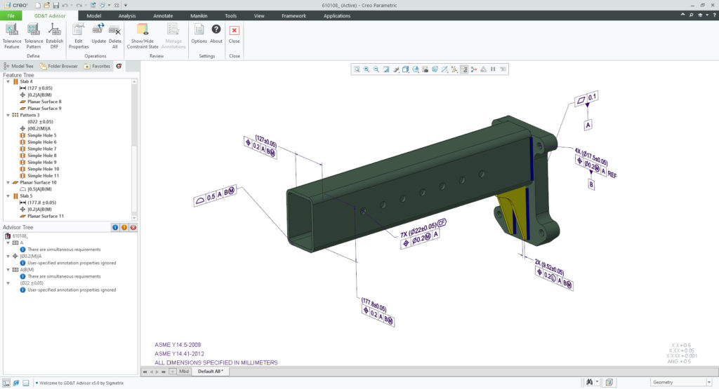
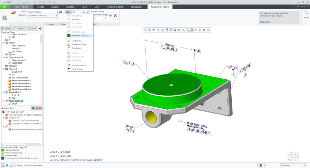
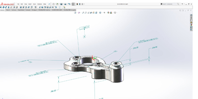
More formally known as model-based definition, MBD is about creating rich “Technical Data Packages (TDP),” which include the 3D model and associated data elements. At the core of the TDPs is the 3D model, along with its associated dimensioning and tolerancing to clearly communicate design intent and geometric form control. Thanks to the TDP, users who sit downstream from engineering can understand and use that model without needing separate 2D artifacts – the information is in the model itself.
MBD is not another way of spelling ‘paperless engineering,’ as if mere convenience were the reason for such a strategic shift. The manufacturers we work with are talking about a broader and grander idea: a different way of approaching the product development, manufacturing, delivery, operations, and service processes so that the 3D model is the source authority.
By implication, these manufacturers are also talking about innovation, and how they might use breakthrough technologies such as simulation, additive manufacturing, and generative design to design better products faster. MBD is as much an approach to corporate strategy as it is an approach to design, product development and manufacturing.
That’s the exciting part – the vision that gets people to commit their time and resources to the effort. I would offer this advice to those who aspire to a model-based journey. Think of a rock climber scaling a cliff face. As he or she ascends, that climber will need to put an anchor in the rock through which to pass the rope.
Your 3D model is that anchor. Start there.
3D model as Anchor
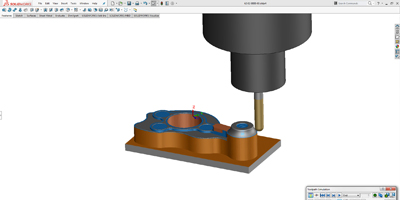
This is no getting around it: every MBD journey starts by looking at your modeling practices and ensuring that your model truly reflects your design. One customer discovered, as they implemented MBD, that they had to train their engineers to know where and how to apply drafts to their injection molded parts, instead of relying on the manufacturing team to do it. Another found that simulation results would be inaccurate unless certain critical features were modeled in complete detail, instead of leaving some geometry details to notes.
Today, I look at the model itself as a precise database for all PMI rather than as a supporting item to create a 2D drawing quickly.
A geometrical product specification is gold for manufacturers.
A word of caution
Next, examine your own mental models and beware of outdated beliefs. We sometimes see those who have (unknowingly) gone halfway with MBD – only to stop on the manufacturing floor. In the past, a certain amount of rework was part of the design process, as was the willingness to accept change at the worst possible and most expensive time. Allow me to be candid. With MBD, your experts on the shop floor will need to learn to place the 3D model at the center of everything they do, too. This will surely help them streamline industrialization of the design, minimize mistakes, and produce the highest-quality output. This will definitely be a change for the manufacturing team, but everyone I’ve talked to has said this is worth it.
Disconnected detours
The worst choices in business are ones you don’t know you’re making. With that in mind, consider whether an MBD journey would, in fact, be less costly in time, money, materials and morale than situations such as the scenario described below.
At one manufacturer, final drawings were made into pdfs and put on a server where all could access them. Not surprisingly, CNC machines soon were decorated with marked-up pdfs showing late-breaking changes. As the model evolved, there was no way other than person-to-person to get the changes to the manufacturing floor. One employee jokingly referred to the ‘sneaker net’. The manufacturing engineers encountered the same situation, and the changes they made on the shop floor often didn’t get to the designers, who unknowingly proliferated errors.
In our opinion, becoming model-based is a journey. To prepare, commit to making the 3D model the source of all authority and then take a moment to reexamine your modeling practices. This will take time, but your reward will be more value for the investment you’ve already made, confidence that engineers can now spend their valuable time doing what you paid them to do, and circumstances more favorable to innovation. That’s what our customers are seeking.
PTC
www.ptc.com


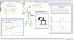 LMS Imagine.Lab 14, the latest release of Siemens PLM’s software for multi-domain system simulation, shows the company delivering on the vision it outlined when it acquired LMS International in 2012—“to provide a closed-loop systems-driven product development solution.”
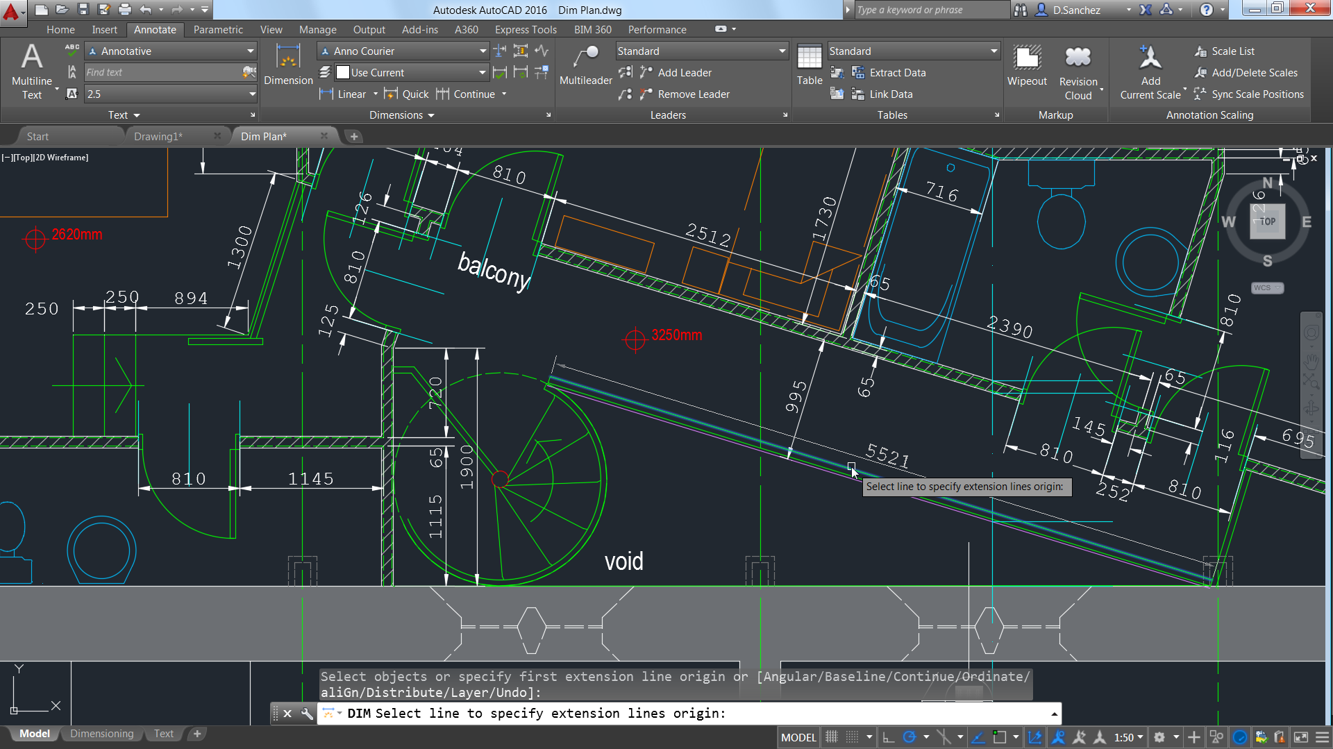
 MecSoft Corporation has announced the availability of RhinoCAM 2015, a major version release for MecSoft’s integrated CAM solution for Rhino. RhinoCAM 2015 includes four CAM modules MILL, TURN, NEST, and ART, each of which run completely integrated inside the Rhino 5 CAD program.