• Skip to primary navigation
  • Skip to main content
  • Skip to primary sidebar
  • Skip to footer

3D CAD World

Over 50,000 3D CAD Tips & Tutorials. 3D CAD News by applications and CAD industry news.

  • 3D CAD Package Tips
    • Alibre
    • Autodesk
    • Catia
    • Creo
    • Inventor
    • Onshape
    • Pro/Engineer
    • Siemens PLM
    • SolidWorks
    • SpaceClaim
  • CAD Hardware
  • CAD Industry News
    • Company News
      • Autodesk News
      • Catia News & Events
      • PTC News
      • Siemens PLM & Events
      • SolidWorks News & Events
      • SpaceClaim News
    • Rapid Prototyping
    • Simulation Software
  • Prototype Parts
  • User Forums
    • MCAD Central
    • 3D CAD Forums
    • Engineering Exchange
  • CAD Resources
    • 3D CAD Models
  • Videos

Jennifer Calhoon

COMSOL Expands in Shanghai

December 15, 2015 By Jennifer Calhoon Leave a Comment

COMSOL, a provider of multiphysics modeling, simulation, and application design software, announced the expansion of its office in Shanghai, China. A larger facility enables continued expansion and recruitment of technical and sales staff to keep pace with the growing COMSOL® software user base in China and increasing demand for COMSOL Multiphysics® and COMSOL Server™ products. Services in Shanghai include sales, technical support, training sessions, and on-site workshops and customer visits.

“We are very excited to expand our office in Shanghai,” said Lei Chen, Managing Director of COMSOL Co., Ltd. in Shanghai. “Training sessions in areas such as multiphysics, mechanical, electrical, chemical and fluid flow will be offered in our new in-house educational facility to teach customers new to COMSOL Multiphysics and COMSOL Server products. More office space also allows us to expand our technical support team to better assist our customers in China. Additionally, we are expanding our localization team to provide more technical material (documentation, model examples) in Chinese.”

The Shanghai office expansion coincides with the latest release of COMSOL Multiphysics® with a more powerful Application Builder and COMSOL Server™. The new version provides simulation experts with a cutting edge user experience in simulation app design and app sharing by integrating highly productive model building, app design, and deployment tools that allow their simulation applications to be shared with users everywhere. With the Application Builder, companies can communicate across multiple departments, knowing that the simulation specialist is able to maintain control, enforce quality standards, and ensure that the results can be trusted.

“Expansion of COMSOL Shanghai office allows us to increase our high quality technical team to support the fast-growing COMSOL community in China,” said Gang (Martin) Wang, Technical Director of COMSOL Co., Ltd. in Shanghai. “Our applications team is dedicated to helping our users learn how to use COMSOL Multiphysics and COMSOL Server and build a wide array of easy-to-use yet powerful simulation apps.”

Comsol
www.comsol.com

Filed Under: CAD Industry News, Company News Tagged With: COMSOL

3D-Printed Extraterrestrials

August 5, 2015 By Jennifer Calhoon Leave a Comment

By Mitch Bossart

Back in 2009, scientists detected an odd-shaped rock by the Mars Exploration Rover Opportunity’s panorama camera.

Figure1
Figure 1 – Block Island detected on Opportunity’s camera

NASA’s Jet Propulsion Lab (JPL) team spotted the rock, now called Block Island, in the images downlinked to Earth after it had driven past the rock. The rover backtracked some 820 feet to study Block Island closer, eventually touching the rock with its robotic arm. The image showed a rock approximately 2 feet in length and half that in height, with a metallic bluish tint that distinguished it from other rocks in the area.

Figure2
Figure 2 – Rendering of Mars Exploration Rover Opportunity

Upon further analysis scientists discovered that Block Island was a meteorite comprised of iron and nickel. A portion of Block Island’s surface indicated exposure when a meteorite is abraded, polished, and etched by windblown sand.

A Piece of Mars on Earth

JPL decided to 3D-print the meteor using its Stratasys Dimension 1200 printer. The final result was a realistic-looking, true-size facsimile of a Martian meteorite.

This 3D-printed meteorite is the first of its kind, made from precise measurements by a rover on Mars. It potentially opens the door to other detailed models of objects and terrain on Mars or elsewhere in the solar system.

Figure3
Figure 3 – Glen Chancellor, 3D-Printer Specialist from GoEngineer, holds a 1/25 scale of Block Island. GoEngineer is a Stratasys reseller in Southern California that also offers SOLIDWORKS and other best-in-class technology solutions.

Challenges in 3D Printing Block Island

Researchers leveraged software, generally used to help navigate the rover, to create depth meshes of the meteorite’s surface from six positions and combined them into a three-dimensional digital model. Block Island was much bigger than the 3D-printer’s build envelope, so JPL researchers broke the computer model of the meteorite into 11 sections.

Figure4
Figure 4 – Eight of eleven sections that became the actual-size version of Block Island

It took over 305 hours to print the parts. Materials included 281.11 cubic inches of acrylic thermoplastic media, along with 37.29 cubic inches of plastic support media to form the support structure inside the rock model.

Researchers then assembled the parts and painted the model to match Block Island’s color based on images from the rover.

For the JPL team, it’s the next best thing to bringing real Martian rock samples back to Earth.

Figure5
Figure 5 – Final 1/1 scale version of Block Island

GoEngineer
www.goengineer.com

3D Printing Industry
www.3dprintingindustry.com

Filed Under: CAD Industry News, Company News, News Tagged With: 3dprintingindustry, goengineer

MecSoft announces RhinoCAM 2015

March 5, 2015 By Jennifer Calhoon Leave a Comment

MecSoft
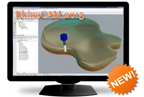
MecSoft Corporation has announced the availability of RhinoCAM 2015, a major version release for MecSoft’s integrated CAM solution for Rhino. RhinoCAM 2015 includes four CAM modules MILL, TURN, NEST, and ART, each of which run completely integrated inside the Rhino 5 CAD program.

All CAM modules were significantly enhanced and improved in this 2015 release to provide customers with a powerful and complete manufacturing platform. Highlight of the release include the Hole Feature Detection and Automatic Machining of Hole Features functionality. Please click on the buttons below to learn more.

MecSoft
www.mecsoft.com

Filed Under: CAD Hardware, CAD Package, CAM, Rhino Blogs Tagged With: mecsoft

SPIROL announces the availability of 2D/3D drawings

November 18, 2014 By Jennifer Calhoon Leave a Comment

SPIROL International Corporation is now pleased to offer 2D/3D drawings of their products!

SPIROL

Drawings are available for both standard and common special items. In all, there are well over 100 different series of products in both metric and inch dimensions. In addition to being able to download each drawing in approximately 40 different file types, all standard products are provided with SPIROL’s item number and the weight for the part. SPIROL’s Engineers are available to review your application needs and work with your design team to recommend the best solution at the lowest assembly cost.

Spirol
www.spirol.com

Filed Under: CAD Industry News, Company News Tagged With: spirol

Harley Thermal launches SolariaPCB add-on to Solaria

November 18, 2014 By Jennifer Calhoon Leave a Comment

Harley Thermal LLC is proud to announce the release of the SolariaPCB add-on to Solaria, the company’s powerful low cost general purpose thermal simulation software tool.

SolariaPCB makes the tedious task of thermal modeling printed circuit boards quick and easy. The ECAD interface brings in every trace, via, component and layer. A component library of over 400 parts is included. SolariaPCB creates a full 3D thermal model of the board and accurately represents every via and trace. Accurately representing all the conduction paths in a PCB model is of particular importance to avionics, satellite and military electronics designers since this is the primary path of heat transfer. Designers of today’s increasingly complex PCB’s, will appreciate the super-fast solvers built into SolariaPCB. Multiple boards can be merged together into a single chassis level model and still solved in minutes.

SolariaPCBSolariaPCB
www.solariathermal.com

Filed Under: Company News, Simulation Software Tagged With: solariapcb

3D printed #cast for the social media age

September 8, 2014 By Jennifer Calhoon Leave a Comment

FATHOM, an advanced technology driven company with an expertise in 3D printing and additive manufacturing, released #CAST. Pronounced Hash Cast, it’s the new way to customize your broken arm cast with personal messages aggregated from your family and friends through social media.

FATHOM

Using the latest in advanced manufacturing technologies and 3D CAD software, an arm can be 3D scanned at a doctor’s office and a one-of-a-kind cast made in a breathable nylon material using an additive technology called Selective Laser Sintering (SLS).

Using the #CAST mobile app, users can approve or reject personalized messages collected through their preferred social networks. Once the maximum amount of characters allowed are approved by the user, a custom fit design is generated and built then delivered to their medical facility and fitted on the user by a specialist.

FATHOM
www.studiofathom.com

Filed Under: CAD Industry News, News Tagged With: fathom

3D Printing in Multiple Materials and Vivid Colors

April 30, 2014 By Jennifer Calhoon Leave a Comment

FATHOM, an advanced technology driven company with an expertise in 3D printing and additive manufacturing, announced that 3D printing services for the Objet500 Connex3 are now available directly at its Seattle-based production center. This is the second Connex3 system added to the company’s list of available service equipment, one of dozens available for additive manufacturing services.

FATHOM

Stratasys introduced the ground-breaking 3D production system at SolidWorks World in January. It is the only machine that creates brilliantly colored prototypes with a range of multi-material options including rigid, flexible, clear, and durable — all in a single build cycle.

“The Objet500 Connex3 offers the most advanced material options out of any other 3D production system in the world”, said Rich Stump, Principal at FATHOM. “Users can create beautiful, and functional, 3D printed parts like never before seen. From concept models and functional prototypes to end-use parts, the application uses really are limitless.”

With the system’s ability to combine vivid color and multiple materials, the Objet500 Connex3 is the only 3D printer that can simulate the precise look, feel, and function of finished products — designs come to life as realistic models earlier in the design process.

“This new system not only offers the best capabilities of any other 3D printer on the market, but it allows users to blend three different materials in a single build cycle,” said Dylan Oliver, Northwest General Manager, adding that the Connex3 is a great platform for future material offerings. “Stratasys has a great track record of making new materials available to customers due to their continuous efforts in composite material development.”

The company is hosting an invite-only event next month where guests will see live printing demonstrations and unique models exclusively created by FATHOM’s design and engineering teams.

“We strive to be our customers’ preferred partner by providing best-in-class equipment, services, and support,” said Oliver. FATHOM recently invested in advanced research and development capabilities to further support its customers’ advanced application needs. “My team is located right in the heart of Seattle, making the latest in additive manufacturing locally available.”

In January, FATHOM announced it was the first 3D printer partner of Stratasys in North America to purchase an Objet500 Connex3 and offer outsourced multi-material color 3D printing services on the West Coast from its Oakland-based production center.

FATHOM
www.studiofathom.com

Filed Under: CAD Industry News, Company News Tagged With: fathom

Hybrid Hex-Tet Meshing in Latest Pointwise Release

April 23, 2014 By Jennifer Calhoon Leave a Comment

Pointwise announces the latest release of its Pointwise computational fluid dynamics (CFD) meshing software featuring an extension of the company’s advanced T-Rex hybrid meshing technique to generate near-wall layers of hexahedral cells.

“As our T-Rex technique for generating hybrid prism-tet meshes with boundary layer resolution continued to evolve, our customers collectively expressed a strong interest in using hex cells in the boundary layer instead of prisms,” said Dr. John Steinbrenner, Pointwise’s vice president of research and development. ”Hex cells are generally thought to provide the basis for a more accurate CFD solution, plus there will be fewer hexes than tets so computations would be faster. Fortunately, post-processing T-Rex’s tet cells into hexes (12 tets per hex) was a natural extension of the existing tet-to-prism combination algorithm.“

Pointwise
This hybrid mesh for the X-38 re-entry vehicle was generated using the latest version of Pointwise’s T-Rex technique and consists of a layer of unstructured hexahedra (green) extruded off the quadrilateral surface mesh (yellow) and connected to the farfield tetrahedra (blue) by pyramids. The orange cells are hexahedra on the symmetry plane. Not shown are prisms extruded off triangles on the vehicle’s base.

T-Rex (anisotropic tetrahedral extrusion) is a highly automated, advancing layer technique for generating a CFD mesh with boundary layer and wake resolution. The technique extrudes layers of high-aspect ratio, right-angle-included tetrahedra outward from a surface mesh. A post-processing operation sequentially combines three successive tetrahedra into a stack of prisms. In this new release of the technique, extrusion from a quadrilateral surface mesh begins with a single pyramid, after which the usual tet extrusion begins. The resulting tets (and that first pyramid) are post-processed into stacks of hexes.

“This new hex capability in T-Rex is just the first step of many that will vastly expand the scope of mesh types that Pointwise can generate,” said John Chawner, Pointwise’s president. “We look forward to customer feedback on this first release of unstructured hex cell generation in T-Rex to guide further developments.”

Pointwise Version 17.2 also includes updated compatibility with CGNS, FUN3D, ANSYS Gambit, STAR-CD, and SC/Tetra; support for the OpenSUSE, Ubuntu, and CentOS Linux distributions; several productivity improvements; and defect corrections.

Pointwise
www.pointwise.com

Filed Under: Simulation Software Tagged With: Pointwise

MecSoft releases VisualXPORT 2014 for SolidWorks

March 5, 2014 By Jennifer Calhoon Leave a Comment

MecSoft Corporation, the developer of computer aided manufacturing (CAM) software solutions, has announced VisualXPORT 2014 for SolidWorks. VisualXPORT for SolidWorks is a direct plug-in for SolidWorks, letting users export their parts in VisualMILL formatted files (.vcp). The solution provides an enhanced workflow for companies that design in SolidWorks and use VisualMILL in their manufacturing process.

MecSoft

“MecSoft is a SolidWorks Gold certified CAM developer, and so we are very familiar with the unique needs of SolidWorks users,” stated Uday Honnalagere, Support Manager for MecSoft. “VisualXPORT for SolidWorks was created as a direct result of the feedback received from our customers. They needed enhanced export capabilities in SolidWorks beyond supporting STL, IGES and STEP formats while not having to give up using our standalone CAD/CAM software, VisualCAD/CAM.”

VisualXPORT 2014 for SolidWorks can be used to export 2D & 3D Sketches (curves), solids with combined faces, solids with separate faces and individual surfaces. With VisualXPORT 2014 for SolidWorks, solids and surfaces can also be exported as NURBS surfaces. It is certified to run inside SolidWorks versions 2009 through 2014.

MecSoft Corporation
www.mecsoft.com

Filed Under: News, Simulation Software Tagged With: mecsoft

Introducing solidThinking Evolve 2014

February 28, 2014 By Jennifer Calhoon Leave a Comment

The Next Generation of Industrial Design Software is Here!

solidThinking Evolve 2014

See it live in our FREE Webinar

SolidThinking

With the release of solidThinking Evolve 2014, we have introduced a new level of usability and efficiency. Model and render like never before with our class-leading new features.

solidThinking Evolve builds on our prior releases by adding the following key features:

  • New Construction Aids and Scene Management
  • Enhanced User Interface Options
  • Improved Modeling Tools
  • Live Linking to KeyShot
  • Many More…

Register for our FREE webinar below to see all of the new features in action and see how solidThinking Evolve can help you develop better products on PC or Mac!

Register Now:

Tuesday, March 11, 2014

9:00 a.m. EST (2:00 p.m. GMT)
2:00 p.m. EST (7:00 p.m. GMT)

solidThinking
www.solidthinking.com

Filed Under: CAD Industry News, News, Simulation Software Tagged With: solidthinking

  • Go to page 1
  • Go to page 2
  • Go to Next Page »

Primary Sidebar

3D CAD NEWSLETTERS

MakePartsFast

Follow us on Twitter

Tweets by 3DCADWorld

Footer

3D CAD World logo

DESIGN WORLD NETWORK

Design World Online
The Robot Report
Coupling Tips
Motion Control Tips
Linear Motion Tips
Bearing Tips

3D CAD WORLD

  • Subscribe to our newsletter
  • Advertise with us
  • Contact us
Follow us on Twitter Add us on Facebook Add us on LinkedIn Add us on Instagram Add us on YouTube

3D CAD World - Copyright © 2021 · WTWH Media LLC and its licensors. All rights reserved.
The material on this site may not be reproduced, distributed, transmitted, cached or otherwise used, except with the prior written permission of WTWH Media.

Privacy Policy