• Skip to primary navigation
  • Skip to main content
  • Skip to primary sidebar
  • Skip to footer

3D CAD World

Over 50,000 3D CAD Tips & Tutorials. 3D CAD News by applications and CAD industry news.

  • 3D CAD Package Tips
    • Alibre
    • Autodesk
    • Catia
    • Creo
    • Inventor
    • Onshape
    • Pro/Engineer
    • Siemens PLM
    • SolidWorks
    • SpaceClaim
  • CAD Hardware
  • CAD Industry News
    • Company News
      • Autodesk News
      • Catia News & Events
      • PTC News
      • Siemens PLM & Events
      • SolidWorks News & Events
      • SpaceClaim News
    • Rapid Prototyping
    • Simulation Software
  • Prototype Parts
  • User Forums
    • MCAD Central
    • 3D CAD Forums
    • Engineering Exchange
  • CAD Resources
    • 3D CAD Models
  • Videos

3DCAD Editor

How simulation helps accelerate the design process

December 17, 2015 By 3DCAD Editor Leave a Comment

by Diane Sofranec, Contributing Editor

The capability to design, test and validate in the digital world helps get products to market faster for less money.

Testing is a critical part of the design process. No matter how complex or simple, every design must be vetted to ensure it works as intended.

Typically, powerful finite element analysis (FEA) or computational fluid dynamics (CFD) software simulate how a design would work.

Simulation software is also useful for conducting virtual tests on designs long before time-intensive and costly physical prototypes are made.

When the goal is to get a product to market quickly, simulation software integrated into CAD software shortens the learning curve because of the similar workflows in these programs.

PTC Creo Simulate is a simulation tool that complements the modeling environment within PTC Creo Parametric.

SOLIDWORKS-Simulation-Baxter-Robot

“Engineers can design their parts and make modifications, but at the same time be able to analyze them,” said Mark Fischer, director of product management within PTC’s CAD segment.

“An engineer can easily use Creo Simulate to find a problem or a potential problem in their model around high stresses or strains and resolve it,” he said. “But the tools are scalable; there’s advanced functionality that an analyst can use as well.”

Simulation tools let you isolate and correct design flaws, reduce problematic variables, improve design quality and rely on fewer prototypes. You can alter models early in the design process, when changes cost less to make.

That’s not to say these simulation tools eliminate the need for experienced analysts; the combination of engineering expertise and powerful simulation tools are still a critical part of the design process. By the time you receive the model, however, its overall quality will be improved, which will help speed cycle time and time to market.

In addition, simulation tools help reduce the bottleneck that often occurs when there is a backlog of designs to test, Fischer said.

“Engineers can verify and validate their designs, and come up with new innovative designs based on those findings early in that design process,” he said. “Any issues that are discovered can easily be modified and fixed, and then the engineer can move on in the design process.”

Can you have confidence in these simulation tools? Fischer thinks so. He said the workflow and user interface must be familiar to users so they can quickly and easily leverage the power of simulation.

“Some engineers might say they don’t have the expertise. But with these simulation tools, they can do simulations early and often, and let the heavy simulations be done by the analysts,” he said.

CollegePark, a company that makes prosthetic limbs for amputees, improved its product by using simulation in the design process. Engineers there use Creo Simulate to design products that are both strong and lightweight. They used the tool to refine the design of a prosthetic foot, making it 40% stronger and 10% lighter.

PTC-Creo-Simulate
PTC Creo Simulate is a simulation tool that complements the modeling environment within PTC Creo Parametric. It lets you design parts, make modifications and analyze at the same time.

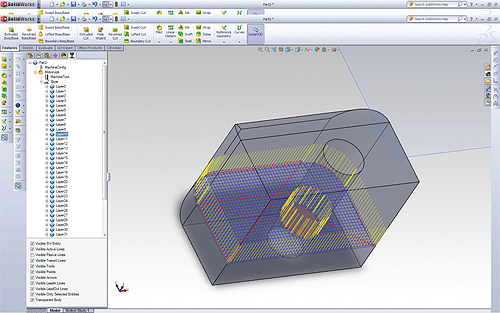
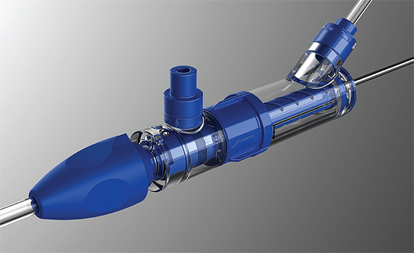
Engineers at Dräger Medical, a manufacturer of breathing and anesthetic equipment for operating rooms, intensive care units and ambulances, use SolidWorks Simulation in their design process. Their challenge was to shorten their development time by half for the life saving devices, a task they accomplished. They reduced the design cycle by 50%, slashed analysis time from 3 months to 2 days, dropped the total number of prototypes from eight to two and saved thousands of dollars by identifying a design flaw early in the design process.

Dräger-Medical-use-SolidWorks-Simulation
Engineers at Dräger Medical use SolidWorks Simulation in their design process to reduce the design cycle by 50%, slash analysis time from months to days, and reduce the total number of prototypes by identifying design flaws early in the design process.

“Using SolidWorks Simulation means that we can run calculations on the various design approaches during the design stage easily and quickly,” said Karsten Hoffman, Dräger project leader. “SolidWorks Simulation saves us time and expense.”

SolidWorks offers several different simulation solutions that help improve product performance and quality by indicating how product designs will behave before they are built. They include SolidWorks Simulation for FEA and structural analysis; SolidWorks Flow Simulation for CFD, fluid flow and heat transfer; SolidWorks Motion for kinematic and dynamic analysis; SolidWorks Plastics for plastic injection molding; and SolidWorks Sustainability.

Karim Segond, founder of E-Cooling, an engineering consultancy that provides 3D thermal and flow analysis, enhancement and development supporting electronics, electric engines, and power electronics, uses Mentor Graphics’ FloEFD simulation tool.

“The biggest benefits I got from FloEFD was that it was embedded; I could work within a CAD system and use parametric CAD models,” he said. “This made it easier to change any geometry and run several variants very easily. Another point that lifted a heavy burden for me is the automatic meshing. Basically, the meshing as I knew it became obsolete and I could spend my time with other things than manually mesh the geometry.”

FloEFD-for-Creo
CFD tools often require a level of experience among engineering users. FloEFD, from Mentor Graphics, takes away much of the prerequisite numerical competence, automating and hardwiring some of, or most of, the numerical settings that would otherwise have to be made manually.

To further emphasize its ease of use, FloEFD, which stands for Engineering Fluid Dynamics, makes it possible for engineers to access its CFD simulation capabilities within their mechanical CAD design environment.

“We believe that CFD as a simulation technology should first and foremost be used to satisfy engineering goals and be used by engineers, not PhD simulation specialists,” said Robin Bornoff, market development manager for Mentor Graphics.

That’s not to say engineers using the software should have no knowledge of the principles of simulation. “You’ve got to have a good understanding of the physics of airflow and heat transfer to be able to correctly construct a simulation model,” Bornoff said. “Although it’s much more automated, it doesn’t take away the need for the engineer using the tool to have a good physics grounding.”

Analysts will always have a role in the design process. But when it comes to fixing design problems, a lot of the day-to-day CFD design simulation work doesn’t require a high level of expertise, he said.

“General-purpose CFD tools are highly capable, functionally rich; there are many different options and choices the user can make that control the numerics of the CFD simulation,” Bornoff said. An engineer who can understand and control the numerics will get good results.

“But the problem is, you need prerequisite experience to choose your CFD tool to get the required results,” he said. “So what we’ve done in FloEFD is to take away a lot of that prerequisite numerical competence, automating and hardwiring some of, or most of, the numerical settings that would otherwise have to be made manually.”

Another use of simulation is to use it to check whether the proposed design is compliant. Designers can accomplish this during the conceptual stage of the design process, when it’s easy to make major decisions about how the product should be configured.

Engineers set out to create an accurate model, and simulation can prove whether they’ve accomplished that goal. Indeed, the more physics phenomena that can be included in any one simulation, the more accurate the final model will be. COMSOL Multiphysics helps engineers solve systems of multiple physics effects as they would occur in nature, empowering them to base their design decisions on accurate data.

COMSOL-corrugated-horn-antenna-results
Model of a corrugated circular horn antenna. Simulation results show the electric field and radiation patterns around the antenna.

“Simulation allows companies to cut costs by reducing the number of physical prototypes and bring innovative products to market faster,” said Bernt Nilsson, COMSOL’s SVP of marketing.

The company also offers COMSOL Server software, which allows access to simulation applications throughout an entire organization, extending the benefits of simulation from conceptual design to manufacturing.

COMSOL-V5.2-From-Model-To-App-FinnedPipe
The Application Builder allows simulation experts to turn a COMSOL Multiphysics model into a custom simulation app that can be shared with a colleague or customer. For example, the thermal properties of a finned pipe are derived from the results of a conjugate heat transfer simulation. The app user can change aspects of the design such as the arrangement of the inner grooves and outer fins.

In addition, the company offers an Application Builder that expands the research and development expertise behind multiphysics simulation to app users who don’t need to know everything that went into the full model. Engineers build specialized versions of their COMSOL Multiphysics models with specific inputs, outputs, and interfaces, and save them as applications. They then send these apps to colleagues and customers who can run them on COMSOL Multiphysics or COMSOL Server.

For example, R&D engineers at Cypress Semiconductor are creating simulation apps for their customer support team to make it easier to explore the outcome of proposed designs while serving customers in real time. Apps such as these can be useful to speed up the process.

Often, the turnaround time for design simulation is slow due to the limited number of analysts who are capable of using advanced CFD tools. As a result, a design may have changed by the time the simulation has been conducted, said Bornoff. Engineers can conduct virtual simulations of their models and make crucial changes that refine and perfect their designs earlier than ever in the design process.

Digimat, from e-Xstream Engineering, an MSC Software company, includes a suite of tools that engineers can integrate within the FEA process to “bridge the gap” between structural analysis and the manufacturing process.

digimat-e-xstream-engineering
Digimat, from e-Xstream Engineering, an MSC Software company, includes a suite of tools that you can integrate within the FEA process to bridge the gap between structural analysis and the manufacturing process.

Digimat-VA makes it possible for engineers to generate virtual “allowables.” The tool, which is powered by a non-linear FEA solution, lets them digitally compare materials, explore material sensitivity to parameters’ variability and get a better understanding of a composite’s performance. The ability to screen, select and compute the allowables of composite materials in a virtual environment saves time and money typically spent on physical allowables.

Solvay Engineering Plastics, which supplies materials for polyamide engineering plastics, used Digimat-MX, Digimat-CAE and Digimat-MAP to determine the possible stiffness and failure of a multi-functional seat pan for use in the automotive market. Simulation predicted three failures early in the design process.

“The added value of predictive modeling with an integrative simulation approach was demonstrated,” said Olivier Moulinjeune, simulation expert, Solvay Engineering Plastics. “Thanks to Digimat local material behavior and failure criteria, we captured the right chronology of all failure events.”

Using simulation tools to design, test and validate in the digital world is akin to creating physical prototypes early in the design process; products get to market faster for less money.

Reprint info >>

COMSOL
www.comsol.com

e-Xstream Engineering, an MSC Software company
www.e-xstream.com

Mentor Graphics
www.mentor.com/products/mechanical/floefd

PTC
www.ptc.com/cad/simulation

SolidWorks
www.solidworks.com/sw/products/simulation/simulation.htm

Filed Under: 3D CAD Package Tips, CAD Blogs, CAD Industry News, CAD Package, Simulation Software, SolidWorks Blogs

Autodesk Fusion 360 uses the cloud to facilitate collaboration, add upgrades

October 15, 2015 By 3DCAD Editor Leave a Comment

by Diane Sofranec, Contributing Editor

Your photos, music and movies are stored on the cloud, so why not your CAD designs, too?

Autodesk’s Fusion 360 is a cloud-based mechanical CAD solution. Officially released at Autodesk University in 2012, Fusion 360 was launched in 2009 through Autodesk Labs as Inventor Fusion.

But it’s not software you install on your computer. A $300 yearly subscription gets you a mechanical, industrial and conceptual design tool, plus frequent updates.

Autodesk-Fusion-360-1
Fusion 360 is a highly collaborative design tool that can take designers from concept to prototype.

Using a cloud-based design tool means every change you make on your design is saved on the cloud and becomes part of a version history. You have the ability to access each version of your design, so every time you open your design, you will see which version you are getting.

Keeping the application on the cloud allows Autodesk to provide quick fixes and add new capabilities. Updates typically occur every eight weeks; some are minor, whereas others are significant. As a result, Fusion 360 has evolved into a highly collaborative design tool that takes you from concept to prototype, providing you have a decent Internet connection.

Since its initial release, Autodesk has added considerable functionality. Several of the latest updates are worth noting.

Collaboration
The ability to access data and share designs no matter where you are, regardless of the device you are using is what Fusion 360 is all about. Because your data is housed on the cloud, you can look at it whether you’re on a Mac, PC, tablet or smartphone and work with your design team from anywhere as long as you’re online.

A Fusion 360 mobile app that works on iOS and Android devices lets you view, mark up and comment on your CAD models. You can easily collaborate by adding others to your project so they can see your progress anytime. The app includes support for more than 100 file formats, and allows you to store and view just as many data formats. To make viewing easier, you can isolate and hide the model’s components and use your touchscreen to zoom, rotate and pan. It also gives you access to design properties and parts lists, and tracks project activities and updates. You can share project information by posting messages, photos and comments. You can also take and share screenshots of any markups made to your design.

If you’re an Apple aficionado, Fusion 360 employs Handoff, which lets you resume what you were doing exactly where you left off as you switch devices. So as long as you’re signed in to the same iCloud account, you can look at your design on your iPhone and then, when you open your MacBook Pro and launch your browser, a simple click will take you to that same design so you can continue working.

Animations
Sometimes you need to show all the components of a product, or how it goes together and comes apart. That’s what makes animations, or exploded views, indispensible. You can add notes, too. This capability works on all iOS devices, so you can share this aspect of your design with clients, manufacturers and the design team.

Autodesk-Fusion-360-exploded-views
Animations, or exploded views, let designer show how products go together and come apart.

Distributed design
Fusion 360’s Distributed Design capabilities allow you to create a couple of different designs and insert one of them into another design. It’s a convenient way for multiple users to work on a design together.

Drawings
The Fusion 360 creators leveraged the AutoCAD Mechanical 2D design tool. In addition, the past few upgrades added mechanical annotations and 2D symbols, making it easier to create patent drawings or communicate with the manufacturing team.

Standard parts libraries
Looking for parts to put in your model? Look no further than the parts library that is built into Fusion 360. Simply find the part you need; one click brings it directly into your design. Autodesk has been working with such companies as McMaster-Carr and Cavenas to create standard parts libraries. The McMaster-Carr parts library is the default and already included; however, you can choose from many others to add.

Application programming interface
Late last year, Autodesk introduced application programming interface (API) support for Fusion 360, and continues to open it up to more and more third party companies. For instance, although CAM capabilities are built in, you can now easily integrate the CAM tools of your choosing.

CAM
Speaking of CAM, 2.5- and 3-axis capabilities make it possible for you to turn your designs into parts. HSMWorks, a company Autodesk acquired three years ago, is fully integrated into Fusion 360 (as well as its Inventor software). This CAM functionality makes it possible for designers to take their products to market, whether they are seasoned professionals working for major corporations or hobbyists launching their dream inventions.

Autodesk-Fusion-360-2
Fusion 360 includes 2.5- and 3-axis CAM capabilities for turning designs into parts.

3D Printing
3D printing capabilities are integrated through Spark, an open software platform just for that. Spark can generate supports for designs that need them. Plus, it lets you control the printer you’re using as well as the outcome. A layer-by-layer preview shows exactly what you can expect.

Autodesk-Fusion-360-3d-printing-capabilities
The 3D printing capabilities in Fusion 360 let designers generate supports when needed.

Training
For a product that’s updated every eight weeks, training is definitely necessary. Autodesk constantly updates its help section with new tutorials to ensure ease of use. Built-in tutorial videos and links are designed to help you get up to speed quickly.

For those who need to learn the basics, there’s Fusion 101, detailed instructions on nine different capabilities. You can learn how to sketch, sculpt, model, manage and collaborate, render, and get the basics on assemblies, drawings, CAM and animations. Each training module takes an hour to two to explore and includes videos for those who learn by watching and printable documents for those who prefer written instructions.

In addition, if you were a SolidWorks user, you can check out videos with more advanced content designed to help make the switch to Fusion 360 go smoothly. Because you already understand 3D design concepts, these videos simply show how the tools and workflows differ in an effort to make the transition easier.

Education
Autodesk worked with the Apple Education team to offer the Autodesk Design Academy iTunes U course. Students and others new to CAD can check out iTunes U for a course in Fusion 360. Autodesk is one of the few businesses with educational content in this space. But because it’s a cloud-based design tool natively written for the Mac, a partnership with Apple seems natural.

Longtime professional CAD users, inexperienced hobbyists and students just launching their careers can easily learn how to use Fusion 360 to create and collaborate.

The road ahead
Collaboration isn’t limited to the members of your design team. To learn what’s next for Fusion 360, its developers include a roadmap in the Autodesk Community section of the application’s website that details the upgrades you can expect to see soon. Such transparency also provides an opportunity to weigh in on what you would like to see in future versions. Sometimes, proposed features include links with more detailed information. Simulation is coming soon, for instance, and Fusion 360 developers have shared what it will encompass and why. They also put out a call for feedback. It’s not everyday you can collaborate with the developers of your CAD application just as you would with the members of your design team.

Reprint info >>

Autodesk
www.autodesk.com

Filed Under: 3D CAD Package Tips, Autodesk, Autodesk News, CAD Industry News, Company News Tagged With: Autodesk

The Evolution of CAD

June 15, 2015 By 3DCAD Editor Leave a Comment

by Darren Chilton, Program Manager, Product Strategy and Development, solidThinking

Designers seeking a solution for creating products for additive manufacturing, look no further than hybrid modelers. Without the constraints of traditional CAD tools, these programs help you explore product designs and create alternatives all in one place.

Computer Aided Design (CAD) software first came onto the scene in the later part of last century to help engineers, designers and other industrial users create accurate, dynamic models quickly. Several programs over the years have done just that: revolutionized the design process, cut turnaround times and enabled more complex product designs. As the industry continues to develop, however, many designers are finding that CAD solutions are too rigid and do not allow enough creative freedom when designing products.

CAD is a great tool for documenting a design after a designer has worked out all the dimensions and details on paper or with physical 3D models. But when it comes to allowing designers the freedom to create new products and experiment with design alternatives, CAD often misses the mark.

A new player is rising in the 3D modeling industry: hybrid modelers. Hybrid modelers pack the power of CAD into a package that is intuitive and includes tools that leave room for greater creativity.

CAD reimagined
CAD programs typically rely on solid modeling, a technique well suited for creating parts to be mass manufactured, but not known for its flexibility. When creating more fluid or organic forms, designers usually prefer polygonal modeling or surface modeling. Each of the three major modeling styles offers advantages and disadvantages. For instance, polygonal modeling makes it easy to quickly flesh out forms, but can be difficult to control the model with exact dimensions. The goal of a hybrid modeler is to blend two or more of the modeling styles into one program that leverages the advantages of each.

The challenge in creating any hybrid modeler is making the different modeling styles play nicely with each other. Most hybrid modelers start as a successful program using one of the modeling styles. When an additional modeling style is packaged with the program, often as a third part plug-in, it may feel disjointed and may not work well with the initial set of tools.

One new program that overcomes this objection is solidThinking’s Evolve. This program was conceptualized as an all-in-one hybrid modeler from the beginning. The program was built to highlight the strengths of each of the three major modeling styles in a cohesive approach. The result is an interface that allows users to seamlessly move between modeling styles.

The core value of a hybrid modeler is the flexibility it gives you. The ability to use multiple modeling styles in one model lets you create the intended forms while still being able to apply precise details with tools like rounds and trims. You also have the flexibility to start a model using one technique then prepare it for manufacture using a different technique.

bicycle-helmet
Clicking the Nurbify button in Evolve 2015 converts the polygonal modeled helmet (left) into a solid NURBS surface (right) with one click.

Above is an example of a bicycle helmet that was designed using polygonal modeling. The designer was able to quickly create the form and design of the helmet, but was left with a model that wasn’t usable for manufacturing. Using Evolve’s Nurbify option, the designer was able to convert the model into a smooth NURBS surface with a single click. The geometry can either be further refined, or sent directly to manufacturing.

Technologies like Nurbify can change the way you approach product design. Instead of creating a mountain of sketches to work out every aspect of a design, you can move into 3D earlier. You can make more accurate decisions earlier in the design process, as well as explore multiple design iterations. Some of the best designs end up being happy accidents that are developed while you experiment with different forms and ideas.

bikeframe
solidThinking’s Evolve was conceived as an all-in-one hybrid modeler. The program was built to highlight the strengths of each of the three major modeling styles in a cohesive approach. The result is an interface that allows users to seamlessly move between modeling styles.

One example is a design for a pen. The designer in this instance fleshed out some basic forms of the pen, then worked through various iterations until a final design was achieved. With Evolve’s flexible set of tools specifically developed for this type of workflow, the designer created these designs in minutes compared to the hours it may have taken in a traditional CAD program.

pen-designs-created-with-solidThinking-Evolve
Using the Construction History feature in Evolve, the designer was able to efficiently create multiple iterations of a pen design.

Creating a one stop shop
In the 3D modeling industry there are several programs that specialize in various parts of the concept creation, modeling, visualization, or manufacturing process. The wide set of options gives you plenty of choices, but often means the model has to be moved between several costly programs along the way.

In addition to creating ease of use between the major 3D modeling styles, hybrid modelers include more complete toolsets to ensure designers work as efficiently as possible. Evolve 2015 includes a completely updated rendering engine that emphasizes ease of use and creates visually stunning renderings.

In this instance, the designer created a design using Evolve, then rendered it using native tools. Thus, Evolve, enables you to keep most — if not all — of your project in one program throughout the process. By packaging multiple functions into one software solution, hybrid modelers are more attractive to emerging manufacturing technologies.

Disrupting traditional manufacturing
One of the most notable emerging technologies today is additive manufacturing. Though the technology has been around for decades, new technologies and tools are making it more accessible than ever. With these manufacturing options, the industry is seeing products with more complex and sophisticated geometry.

Additive manufacturing enables a complete shift in how you are able to design products. 3D printers can make forms that are not possible using traditional methods. Beyond being able to make low volume parts faster, you are able to make parts lighter without sacrificing structural integrity.

bicycle-part
The original part (left) was optimized to remove unnecessary material and resulted in an organic, efficient form (right) ready for 3D printing.

Take the part above, the image on the left is the original part prepared for traditional manufacturing. At 6.2 lb, there is room for weight reduction, but traditional manufacturing methods are not able to handle the complexity of the more efficient structures. In this case, the designer optimized the part in solidThinking Inspire by applying the required loads and constraints, which then removed all the non-essential material. The optimized part was then prepared for manufacturing using Evolve. The result, shown on the right, is an organic structure that reduced the part mass by 35% and brought the final weight below 4 lb. The complex structure is not suited for traditional manufacturing, but is easily handled by a 3D printer.

Similar to traditional manufacturing methods, traditional CAD programs have difficulty handling complex organic structures. To create these structures, designers rely on hybrid modelers and their ability to create organic geometry.

Hybrid modelers and additive manufacturing
Additive manufacturing is making it easier than ever to create new products and prototypes. Similarly, hybrid modelers make it easier to conceptualize the products and prepare them for manufacturing. For this reason, many designers consider hybrid modelers a great solution for additive manufacturing.

coffee-cup-stack
Creating quick iterations of an initial concept is ideal for users preparing products for additive manufacturing.

With Evolve software, the designer can quickly and easily create variations of a design, as shown here with unique mugs. In the world of additive manufacturing, the designer isn’t locked into manufacturing a certain number of products to save costs. This allows greater design flexibility and the opportunity to make changes even after manufacturing has begun.

Using a traditional CAD program, a designer would have to create each one of these iterations separately; this is where hybrid modelers provide a significant advantage. Once the base mug is designed, the designer can create and experiment with several designs in just minutes. The iterations of these designs were powered by a unique construction history feature. While working in the hybrid environment, a designer can make changes to the original design and the entire model updates responsively.

“Evolve’s Construction Tree history lets you seamlessly go back and edit your models without having to start the process over; this is key to help expedite the timeline,” said Jared Boyd, product design manager at Dimensions Furniture.

In addition to making it easier to iterate and create designs, hybrid modelers make it easier to communicate with various members of the manufacturing process with options to export the model in most major 3D formats or create photorealistic images and animations.

CAD, evolved
CAD programs can be beneficial in certain areas of product development, but with the introduction of hybrid modelers, designers are free from the constraints of traditional CAD programs and can create innovative products faster and easier. Not only do these programs lead to greater efficiency, they also ease communications between designers and vendors while leaving plenty of room for creativity.

The future relationship between additive manufacturing and hybrid modelers is exciting. Huge advances are already being made in industries with high cost, low volume products like aerospace, defense and medicine.

Reprint info >>

solidThinking
www.solidthinking.com

Filed Under: CAD Blogs, CAD Industry News, General Blogs, Rapid Prototyping Tagged With: solidthinking

Progress in closing the product lifecycle’s loops

April 15, 2015 By 3DCAD Editor Leave a Comment

by Peter A. Bilello, President, CIMdata

Despite progress made by vendors and users, there are still product lifecycle loops that must be closed to facilitate the development, manufacture and support of globally competitive new products.

There has been significant progress made by both users and solution providers in closing the many still-open loops that exist throughout the product lifecycle and, for that matter, throughout the extended enterprise.

For many years, the PLM industry has greatly benefited from a steady stream of improvements in collaboration among ever more diverse enterprise groups—in data interoperability, for example, and in the transparency of workflows and processes. The development, manufacture and support of globally competitive new products are, however, still hamstrung by the remaining open loops new and old.

Within manufacturing, digital communication problems are nearly all resolved thanks to closed-loop controls on computerized production machinery, embedded quality assurance (QA) systems, statistical process control (SPC), manufacturing execution systems (MES), supervisory control and data acquisition (SCADA) and factory floor automation in general, plus engineering support and programming. All this technology is summed up as “digital manufacturing,” and, as with the Internet of Things (IoT), enhancements continue among competing sets of standards.

New sets of open loops are appearing around additive manufacturing/3D printing technology. In recent years, additive manufacturing has burst out of low-volume, highly customized production and prototyping into manufacturing in general. This loop-closing, game-changer melds design and forming into a machine-and-software package. That package, however, creates new connectivity needs with the rest of the enterprise. Prototypes have always been the lifecycle loop closers between design and manufacturing and between product development and customers.

Male-Anatomy-

In engineering, much remains to be done in closing the loops despite the almost universal employment of the tools and solutions in computer-aided design (CAD) and computer-aided engineering (CAE) with its simulation, analysis and optimization capabilities. There are big pushes from engineering managers striving toward the so-called “single source of truth” and for more and better application program interfaces (APIs).

Among the many engineering challenges is the difficulty of verifying accurate translation of files between CAD/solid modeling and CAE systems with their dozens of file formats and versions. Ensuring the interoperability of these files with automated bidirectional file exchanges remains a headache, especially in large enterprises.

Between engineering and manufacturing, open loops appear regularly with each new product, its processes and new factory technology. With so much at stake, however—production bonuses, incentive pay, reputations—nearly all such loops are quickly closed. The usual strategy is engineering change management: fully documented and often partially automated. One successful approach is the U.S. Food and Drug Administration’s Corrective Action Preventive Action (CAPA). CAPA, an offshoot of quality assurance, seeks to identify flaws in medical devices and surgical implants, correct them in manufacturing as soon as possible, and then document what was done to avoid a recurrence.

Between engineering, manufacturing and finance, a big remaining challenge is the bill of materials (BOM) in its many forms—the as-designed BOM, the as-engineered BOM, the as-manufactured BOM, and so on. Generated and managed with PLM and often executed by enterprise resource planning (ERP) systems, BOMs themselves are loop closers. PLM-ERP connectivity and interoperability are steadily improving, but some open-loop issues are resolved only after time consuming face-to-face meetings.

Also closing loops are supply chain management (SCM) and customer relationship management (CRM). Both systems bear directly on the product lifecycle, but even the best of these implementations leave some loops open—among them, risk management. This, of course, is the realm of the prototype.

After a product leaves the factory, closing the loops is hit or miss. At best, design engineers and manufacturers get sporadic feedback from “the field,” very little of it useful. Field-service technicians are getting better at communicating with outsiders, but much remains to be done. The IoT is already proving valuable to them, if not yet indispensable.

In users’ hands, the situation is different. New input and feedback loops appear constantly in social media and close rapidly. Cellphones and video cameras monitor the customer “experience,” tracking shoppers through store aisles to reveal how they choose products. Many retail and apparel decision makers rely on these direct, immediate feedbacks plus analytics. Traditional customer focus groups are falling into disuse.

Closing the loops at the end of a product’s useful life is still being explored. The end-of-life challenge is to pull obsolete and worn-out products into next-life cycles of refurbishing, remanufacturing and re-purposing. This is the Circular Economy, which addresses risks to environmental sustainability caused by population growth and increasing consumption.

There are loops to be closed beyond these, however. The ultimate loops connect the physical world and its digital representations in the human mind. The most promising technique for linking them is virtual reality (VR). VR is the computer generation of lifelike, three-dimensional video representations of processes—interactive, animated and high-resolution.

VR merges CAE technologies with electronic/optical scans of the physical environment being examined, usually with high-performance computing (HPC). Pioneering VR efforts include Ford’s analyses of assembly line ergonomics and Lockheed Martin’s studies of F-35 Lighting II warplanes aboard aircraft carriers. VR is moving into medical design, construction and infrastructures.

artificial-heart-holograph
A visualization of the ways VR imaging can connect the digital to the physical; in this case, a holograph of an artificial-heart design study rendered in SIMULIA from Dassault Systèmes. Image courtesy of Dassault Systèmes

VR is available as “immersive engineering” systems with room-sized display projections that surround the user with digital data and video and “augmented” reality that relies on 3D head-mounted displays. The latest in augmentation is the Microsoft HoloLens, a wireless headset display that generates interactive holograms; users say holograms enhance comprehension of complex products and systems with visual parallax for depth perception. Microsoft’s January 2015 launch of HoloLens put it ahead of Google Glass, which was pulled off the VR market for a time, and Facebook’s Oculus, still in development.

microsoft-hololens
Microsoft HoloLens, launched in January, is a wireless headset display that generates interactive holograms that are said to enhance comprehension of complex products and systems with visual parallax for depth perception.

Product developers and manufacturers in the medical industry are well aware of the benefits of closing loops in surgically implanted devices, for example, as the SIMULIA image shows.

Infrastructure operations have virtual-to-physical challenges like those of regulated industries. A company called C3global helps users tackle them with infrastructure analytics, asset performance and asset lifecycle management. The company’s tools and strategies close loops between IT and operations in utilities (water, oil and gas) and electricity transmission. The company, which was recently acquired by Bentley Systems, uses configuration management, asset health monitoring, inspection, maintenance, and compliance.

Technology is also closing loops that are entirely in the physical world. In Japan, drone aircraft with scanners are replacing ground-based surveyors at construction sites, speeding up Komatsu’s introduction of automated earthmoving machinery and helping to solve a labor shortage. The Komatsu approach, called Smart Construction, goes far beyond what can be achieved with satellite-based GPS technology.

The same virtual-to-physical challenges drive in the decades-long quest for viable artificial intelligence, or AI. AI researchers seek to close the loop between human brain and computers with digital equivalents to human reasoning, learning, natural language processing, perception and much more. In academia, AI systems are built on mathematics, psychology, linguistics, philosophy, neuroscience and computer science. Progress in AI has never been smooth, but Apple, Google, Facebook, Microsoft, IBM and others have made significant commitments to furthering AI development.

To place loop closing in its broadest context, it is hard to find a technology trend from any place or from any time period that isn’t a loop closer. For millennia, technology has linked whatever is happening in our immediate environments to the human brain. This is much more than a mere linking of the physical and digital realms. The real role of technology, right up to today’s PLM solutions, is to connect the otherwise unconnectable. Connecting the unconnectable is much more profound often than technology’s humdrum everyday label, “the extensions of man.”


Closing the loops: micro and macro

Here are two very different examples of closing the loops. Each can be seen as micro and macro perspectives.

In the realm of the practical everyday business, showing the way is a CIMdata client that leases and services video game consoles. These devices have printed circuit boards, microprocessors, motherboards, card readers and built-in printers. All of these need periodic attention, as do casino slot machines and banks’ automated teller machines, which are similar in many ways.

After a thousand cycles, the consoles are brought in from gaming arcades for cleaning inside and out. After 10,000 cycles, which is usually several months, they are refurbished to original condition. After 100,000 cycles, or several years, the consoles are overhauled and remanufactured to new specifications and then repurposed to new types of games.

In the conceptual realm of closing loops is the Ellen MacArthur Foundation based in Cowes, UK, which acts as a catalyst for the Circular Economy. The Circular Economy is often expressed as having a steady supply of clean clothes without buying a washing machine. The Circular Economy focuses on what happens after a product’s original life ends, a role increasingly filled by the IoT and PLM as it is restructured into a true end-to-end enterprise innovation platform.

For physical goods, the Circular Economy is regenerative and restorative, “cradle to cradle” rather than “cradle to grave,” turnaround rather than termination. Instead of one-way trips to the scrap yard, obsolete goods get new lifecycles satisfying new requirements; worn-out products get new lives as something else. A new education and certification group, Cradle to Cradle Products Innovation Institute, was launched last year in San Francisco.

A European Commission report titled “Manifesto for a Resource Efficient Europe” has drawn considerable attention to the Circular Economy. Commissioned by the MacArthur foundation and developed by McKinsey, the report estimates that manufacturers could save materials costs of up to $630 billion annually by 2025.

Thanks to the Circular Economy, it is conceivable that the notion of obsolescence—planned or naturally occurring—is itself destined for the scrap yard.


Reprint info >>

CIMdata
cimdata.com

Filed Under: CAD Industry News, Company News Tagged With: CIMdata

Inverse-kinematics software helps design modular robots for 3D printing

March 1, 2015 By 3DCAD Editor Leave a Comment

by Vojislav D. Kalanovic, President of Flexible Robotic Environment, Div. of Biocommerce

Robotic systems being used today, for the most part, lack modular flexibility and other elements that allow easy integration, which often prevent an integrator from bringing them to market quickly. These deficiencies also prevent them from being able to tackle non-serial jobs in a timely and cost-effective manner.

In order to improve robotic system development efficiencies, Bicommerce has created a modular software solution that deploys a user-friendly set of tools that open robotic integration to a broader spectrum of users and markets—from a “bread maker” up to the level of a professional system integrator.

VDK-6000-robotic-metal-3D-printing-machine
The FRE solution was used to create the VDK 6000 robotic metal 3D printing and repair work cell that automates refurbishing, rebuilding, and/or creation of metal components using subtractive and additive technology.

The Flexible Robotic Environment (FRE) is a new, patented technology used in robotics that builds a robot around an application instead of trying to “squeeze” an application within the working volumes that are defined by the physical constraints of a spatial kinematic chain.

In this article, we’re going to look at the FRE application being used with Aerotech’s motion components to form a unique, six degree-of-freedom (6DOF) VDK 6000 Robotic Cell for metal 3D printing and metal part refurbishing. The VDK 6000’s advanced metal printing and metal removal capabilities reparation processes are widely used in industry today.

The Flexible Robotic Environment (FRE)
FRE is robotic software that combines mechanical and motor/drive components with proprietary inverse kinematics software and controls. This configurable and interchangeable, multi-degree-of-freedom robotic package allows the user to “shape” the workspace using standard motion elements. Users can also create a distributed 3D mechanism according to a specific need. Such a mechanism then employs all of its DOF simultaneously in order to provide a desired spatial relationship between a tool and a part at any given instant in time.

The flexibility of the FRE solution permits various systems to be built with virtually the same parts. Examples of this are Bicommerce products, such as the VDK 1000 6DOF material removal system, the VDK 3000 6DOF laser deposition system, the VDK 4000 6DOF direct-write system, the VDK 5000 4DOF ultrasound inspection system, and the VDK 6000 6DOF cold spray system. FRE systems can be expanded at any time and individual components can be replaced and/or exchanged with ease.

The FRE software was used to create the VDK 6000 robotic metal 3D printing and repair work cell that automates refurbishing, rebuilding, and/or creation of metal components using subtractive and additive technology. The VDK 6000 provides a unique, modular motion solution and is designed to execute multiple operations on a single station, enabling production of “first time right” parts—as well as their repair. The VDK 6000 helps deploy the most advanced metal printing and metal removal capabilities for well-established reparation processes widely used in industry today, bringing about faster re-deployment at a lower overall cost.

VDK 6000 offers an auto-connect robotic tool-changer for integration with a variety of conventional and non-conventional processes, such as cold spray, milling, laser scanning, ultrasonic inspection, thermal spray, polishing, laser deposition/drilling and plasma-welding. This flexibility allows various combinations of subtractive and additive manufacturing for 3D printing and repair with a single-system solution.

FRE inverse kinematics capabilities mean that axes are broken into a spatial placement having the best error minimization configuration for a given application. With the FRE approach, VDK 6000 can be scaled up or down depending on customer needs.

The VDK 6000 was built using Aerotech motion components for all six axes. Aerotech components include direct-drive linear motor and ball-screw-driven linear stages, worm-gear-driven rotary stages, drives, and Aerotech’s A3200 machine controller. The accuracy and durability of Aerotech motion components are essential to the precision performance of the VDK 6000 system.

Plotting a path via the SolidWorks API
One of the main features of the VDK 6000 is the path-planning program based on an Application Programming Interface (API) developed for SOLIDWORKS. This capability allows the user to path plan in a user-friendly setting, while exporting motion files that are specific to the hardware configuration, composed in a variety of ways in space and where path-planning is not always intuitive.

The SOLIDWORKS-based API allows the user to:
• create a simple path on a given solid
• create multiple paths that are necessary to perform cladding on a given solid/part
• create slicing models and subsequent paths necessary to create a part provided as a solid model

Creating 3D paths
Users can create a 3D direct-write deposition path on a specific part by using the API that is appended to a CAD package.

3d-direct-write-deposition-path
To create a 3D direct-write deposition path on a specific part, use the API that is appended to a CAD package and executed as shown here. This screenshot shows a 3D path (left) and 3D path formed on an existing 3D surface (right).

Sometimes an application requires a cladding operation, which is the bonding together of two dissimilar metals. When this is required, the user selects surfaces on a given part that are intended for cladding using a mouse selection.

Once the surfaces are selected and cladding parameters are assigned within the API environment, a cladding path is created with only a “click.”

Users can also use the API to select and assign specific tool orientations that are to be used during the cladding process, as well as process parameters including peripheral power, I/O control, speed assignment, cladding direction and tool orientation.

part-ready-for-cladding

user-selected-part-ready-for-cladding
The top screenshot shows an existing part ready for cladding. The bottom screenshot shows the user-selected surfaces of the part for cladding.
cladding-path
Once users select the surfaces that require cladding and the parameters are assigned within in the API, a cladding path is created as shown here.

Creating 3D slicing paths
The API also allows the user to build a part using a slicing application. Once the part is selected within the API environment and the parameters are assigned, a click of a mouse produces a slicing diagram.

sliced-solid-transparent-view
This screenshot shows a sliced solid with a transparent view depicting tool orientations and active paths.

Once the fast and user-friendly path-planning process is complete, you can export the motion path directly into the operating environment of the VDK 6000 for immediate execution. Every FRE system comes with a custom MMI making them even more intuitive for the end-user.

In conclusion…
The robotics industry today lacks the degree of modular flexibility that allows quick and easy integration. The Flexible Robotic Environment (FRE) software solution combines mechanical, motor, and drive components with proprietary inverse kinematics software and controls, resulting in a modular, cost-effective, highly innovative, configurable, and interchangeable multi-degree-of-freedom robotic package that can be applied in many low- to high-level applications.

Reprint info >>

Aerotech
www.aerotech.com

Filed Under: CAD Industry News, News, Rapid Prototyping Tagged With: aerotech

A Picture’s Worth a Thousand Words: Why Rendering is Increasingly Important to Product Development

April 9, 2014 By 3DCAD Editor Leave a Comment

Engineers increasingly use rendering tools to create photorealistic visualizations of products as they evolve throughout development to speed concept approvals, identify problems, and sell products.

We’ve all seen them; glossy, slick, perfectly lit product shots that look as if they were taken with a pricey, high-end camera. The vast majority of the time those product shots aren’t real at all, but rather computer-generated, photorealistic renderings of products, many of which don’t even exist yet in the real world. In addition, engineers and designers—not teams of CG specialists—are often creating these renderings.

Product visualizations created with rendering software help the product development process in myriad ways. They help “sell” ideas or concepts long before they exist in physical form; communicate important product information to customers, such as instructions on how to assemble or use new products; help engineers identify design problems; and can shorten time to market.

Josh Mings, an engineer, popular CAD blogger at SolidSmack, and marketing manager at Luxion, explains how today’s rendering tools facilitate collaborative design. “Designers and engineers have incredible opportunity to visualize their ideas. In the past, we were limited to whatever screenshots we could work up or, at best, arduously creating an exploded or cutaway view,” said Mings. “Now, 3D rendering software allows us to create visuals that look as real as the end product, communicating the idea before a piece of material is even cut.”

Tim-Feher-Dodge-Viper-Interior
This rendering of the interior of a Dodge Viper was created using KeyShot software by Tim Feher.

What is rendering?
Rendering is the process of creating an image from a model by means of software. Used in architecture, simulators, video games, movies and visual effects, but this article will focus on its use in design visualization. These product visualizations can be used throughout the design process, from communicating early concept ideas to assessing customer interest in proposed product ideas to helping “sell” final products online or through marketing and sales collateral.

Rendering gives the final appearance to models with visual effects, such as shading, texture mapping, shadows, reflections and motion blurs. Thanks to improved rendering algorithms and hardware acceleration, the software is more powerful than ever. Add to that the fact that high-end engineering workstations are now available at all-time low prices, no one should be left out of the rendering game.

While rendering was once done exclusively by specialists, more engineers and designers are embracing these tools. Kathleen Maher, vice president and analyst at Jon Peddie Research, has covered rendering technology for years and has seen its evolution from being a tool used by specialists to more widespread use by CAD users.

“Rendering has always been part of the design process, though it has usually come at the end off the design process and has been a function of marketing,” says Maher. “Renderers have often been specialists, and given the complexity of design models they have frequently found it more efficient to recreate models rather than use the original 3D models.  That is changing as the CAD companies adapt to new capabilities.”

Where rendering fits in the product development process
Product designers and engineers typically render product models during several different stages of product development. Rendering is commonly done both early during concept development to facilitate buy-in and then again after 3D CAD models are completed to create the visual assets used to sell and support the final product.

L.A.-based industrial designer Gary Fitzgerald uses The Foundry’s MODO software to create photorealistic renderings to speed up concept approval by his clients in the automotive, transit and product design industries. His process is somewhat unique. He uses MODO as a 2D/3D mash-up for what he calls “sketch modeling” in the early phases of concept development. For him, the ability to work in 2D and 3D simultaneously is a big advantage.

AirBloc-Cardiovascular-Access-tool
This rendering, created by Gary Fitzgerald using MODO software, is an early digital mockup of the AirBloc Cardiovascular Access Tool. Designed and manufactured by EP Dynamics, the AirBloc received FDA clearance last year and is now being used in cardiac procedures.

Fitzgerald starts with a 2D sketch underlay, followed by quick, loose 3D geometry. Then using MODO’s 3D painting toolset, he can quickly sketch detail ideas directly on the 3D surface before looping back to create 3D geometry again. This iterative process is “about getting the right decisions made, not that each design is perfect,” says Fitzgerald. “It’s about getting the right decisions made in a timely fashion.”

Dave Vogt, an industrial designer at SkullCandy, says that his company once outsourced rendering to a service bureau but has brought it in-house, saving significant money and time with turnaround time “now days not weeks.” He explains how the process is different, depending upon the stage of development.

skullcandy-headpones
Skullcandy previously outsourced all its rendering to an outside service bureau, but now renders all of its product models created in SolidWorks using Keyshot rendering software. The Aviator family is the latest release of Skullcandy’s line of lifestyle-based audio products.

For concepts, the process is fairly organic; designers have room to decide colors, look and feel. After engineering, however, the final look of the product has been specified in detail and the process of rendering is more constrained. “There’s a lot of things that are flushed out through costing and production—whether it’s form or complexity of a part or materialization of a part,” says Vogt. “So when we get the 3D model back, I pretty much know exactly where things are going to go, how things need to be materialized, etc.”

Chicago-based MINIMAL is a product design firm that creates and markets its own products but also delivers customized design consulting services to outside clients. Dustin Brown, an industrial designer with MINIMAL, says that MINIMAL designers render models throughout the design process.

LUNATIK-TAKTIK-iphone-case
Chicago-based product design firm MINIMAL uses various CAD software to create product models, which are then rendered using Rhino and the V-Ray render engine from The Chaos Group to create exploded views of its products, such as the LUNATIK’s TAKTIK iPhone case.

“At MINIMAL, we begin rendering very early in the design process with quick 3D models that capture basic mechanical or aesthetic thoughts, which are presented to clients in the form of photorealistic renderings,” says Brown. “We continue to update renderings during development as new features are added or other changes are made to project requirements. At the conclusion of a project, we typically provide high-fidelity renderings for our clients’ internal use.”

For the company’s in-house brand LUNATIK, the designers take rendering one step further and create multiple views of its products for use on its e-commerce platform as well as for sales, advertising, and marketing materials. The detailed CAD models are created using several CAD packages, such as Rhino, SolidWorks and PTC’s Creo.

Vendors develop renderers that fit CAD-driven workflows
Rendering software vendors have worked hard over the past several years to gain a foothold in the CAD market. Considering the fact that there are hundreds of thousands of users in the entertainment world, but million of users in the CAD space, it’s a smart move. To do so, however, they have had to take into account how engineers work and the workflow as it pertains to product design, which is clearly different than folks making movies, videos and games.

Maher explains how CAD vendors have made it easier for engineers and designers to incorporate rendering into current product design processes. “CAD users’ desire to integrate analysis, simulation, and rendering into the workflow has resulted in the development of better tools to prepare models, to pare models down to the essentials but keep the information connected,” said Maher. “So rendering can also be performed throughout the process to better understand how changes will affect how the end product will look in the real world.”

One such feature developed to improve the integration of workflow between rendering and design enables a user to continue to develop their CAD models and renderings simultaneously. When changes are made to the model, the rendering software automatically updates the render file to reflect those changes. In KeyShot, this functionality is called Live Linking; in Bunkspeed, it’s called Live Update.

SkullCandy’s Vogt describes a common scenario in which Keyshot’s Live Linking would be useful. “If I had to change the 3D model a little bit, for example, to slightly change the position of the cable. The headphone assembly, which is made of many different components, is fine but the cable needs to be moved over two inches. It’s a pain to start from scratch to redo all that, but with Live Linking, you can just update the file and it recognizes what parts changed and it updates the Keyshot render file. That’s super helpful.”

Rendering in the Cloud
One issue with rendering CAD models is that it requires substantial computing resources, especially when working with large, complex assemblies. Another issue revolves around the cost of the software and the hardware necessary to run it. Start-up Lagoa has introduced a solution that eliminates both of those issues: cloud-based rendering.

Lagoa is a web-based platform for 3D visualization and rendering that enables users to create high-quality, photorealistic images quickly and easily without buying any high-end hardware or software. The platform supports over 40 different CAD formats, including assembly and part files.

The company offers a Community version that users can try out for free. The Professional version is available for $50 per month and includes 100 GB of cloud storage and unlimited rendering time. For companies that need rendering tools on a limited basis and don’t want to take the time to learn how to use rendering software, the Lagoa platform might be the ideal solution.

Reprint info >>

Bunkspeed
www.bunkspeed.com

The Foundry
www.thefoundry.co.uk

Lagoa
www.lagoa.com

Luxion Inc.
www.luxion.com

Chaos Group
www.chaosgroup.com

SolidWorks Corp.
www.solidworks.com

Rhino3D
www.rhino3d.com

Filed Under: CAD Industry News

e-Xstream engineering Announces New Release of Digimat

January 23, 2014 By 3DCAD Editor Leave a Comment

e-Xstream engineering, an MSC Software Company, and software developer of Digimat, a nonlinear multi-scale material and structure modeling platform has announced the new release of Digimat 5.0.1. The new capabilities in this release significantly improve the user friendliness of analyzing fiber reinforced plastics and the accuracy of analyzing unidirectional (UD) and woven composites.

MSC Software

Release Highlights:

New User Interface for Reinforced Plastics Analysis
Digimat-RP (“Reinforced Plastics”) now provides engineers with a guided workflow tool that aids in the setup and streamlines the process of accurate analysis of plastic parts in a robust, fast and easy manner. It bridges the gap between injection molding and nonlinear FEA of plastic parts.

The new release supports the setup of 3D analyses with Marc, MSC Nastran, Abaqus, Ansys, and LS-Dyna based on Moldflow, Moldex3D, Sigmasoft or Timon 3D processing results. All Digimat solution technologies are supported. Jobs can either be run and monitored on a local computer or packaged for the remote solution on a cluster. Digimat-RP is an intuitive 3-step process that enables a part engineer (not necessarily a material expert) to do predictive analysis of plastic parts using one single process oriented product (RP) instead of the original four. RP is easy to learn and to use by “non-experts”. The experts can continue to use the general-purpose building blocks and prepare the models for easy use in RP.

Progressive Failure of UD Composite Materials
Digimat now offers a Matzenmiller-Lubliner-Taylor (MLT) based model for the progressive failure of UD composite materials. Failure progression includes individual damage control functions as well as stabilization of failure progression for coupled analyses. In initial studies, 97% accuracy on open hole tension test could be reached.

Nonlinear Multi-Scale Modeling with Digimat and Nastran Sol 700
MSC Nastran SOL700 is now available in the Digimat-CAE/Nastran interface supporting MSC Nastran 2013.1.

Improved Robustness for Woven Composites
The Hybrid solution method has been enhanced to support elastic, elastoplastic and elasto-viscoplastic material models for woven composites including per-phase failure.

Thermal & Thermo-Mechanical Analysis
Anisotropic thermal conductivity can be used in coupled analyses with Digimat-CAE/Abaqus. Thermo-mechanical analyses are available via Digimat-CAE/Marc. Robustness has been improved by offering RE of TEP material models in MX and the support of TE and TEP within the Hybrid solution method.

MSC Software
www.mscsoftware.com

Filed Under: Simulation Software Tagged With: mscsoftware

CAD Goes Social

January 15, 2014 By 3DCAD Editor Leave a Comment

Are engineering software developers pushing the collaboration envelope so that distributed users can edit complex 3D models at the same time?

Ever since the advent of the Internet and the World Wide Web, many CAD/CAE/CAM companies have been trying to leverage online technologies so users in distributed environments can “get more social” to improve their designs. For example, years ago, CAD software already featured tools such as embedded chat that let users communicate with each other remotely one-on-one or in small groups. Currently, many packages include hooks to social media tools such as YouTube videos and online forums. In fact, individuals in all areas of CAD are engaging with each other like never before and it is social utilities on the Web making this possible.

But what about pushing the social collaboration envelope by giving remote users the capability to edit complex 3D models online at the same time? This idea actually arose as early as the mid-1990s with the former CoCreate, which ran its CAD software on a server, developing a system that let team members control the cursor and thereby work concurrently.

Nanosoft’s Evan Yares said, “Previous collaboration features were technically interesting, but they failed to impact the market. However, improved standards along with other more advanced enterprise applications might now make the concept more realistic. In fact, current research at Brigham Young University uses existing high-end CAD packages and ties them together with a ‘game engine’ framework. Students work together as if in a multiplayer game to edit 3D models while wearing headsets that let them talk together as they work. The researchers claim that such simultaneous group access leads to significant productivity improvements.”

To understand the concept better, consider the simple analogy of editing a document in Google Docs, a cloud-based application that lets enabled users simultaneously open and edit a document from anywhere. The approach works well as long as measures are in place to prevent users’ edits from “colliding.” But editing a CAD model poses more challenges because models are often built using a recipe of uniquely related and ordered features. Any change in a defining parameter by an uninformed user could cause the model to crash.

This all begs the question: Has the rise of more advanced technology caused major developers to create tools to support the concurrent editing of complex 3D models?

Asynchronous collaboration on the forefront
“As described, concurrent collaboration is cutting edge because most engineers don’t see the value of editing a 3D CAD model simultaneously with other users,” said Rob Stevens, VP of Sales and Marketing, of the online site GrabCAD. “Our service is mostly asynchronous.”

Basically, GrabCAD lets users upload and download free CAD models—not exactly a new concept—but the company has a slightly different take. Say a bike frame manufacturer is designing a frame and wants to put wheels on it. Although the company doesn’t make or sell wheels, it spends the time to design the wheels anyway just to be able to showcase the model. In GrabCAD’s approach, because users have already uploaded models of bike wheels, the bike manufacturer merely needs to find an appropriate model to put wheels on its bike.

“From the collaboration angle, our users are professional engineers who want to share their designs with a small group and work together on a project,” said Stevens. So that everyone in the world can’t see the work, we launched Workbench, a private visualization tool for CAD.”

The tool lets designers start a project online and drag files like a CAD model, image, and movie into a project. Designers type in the email addresses of those they want to share the design with, providing a link to the design. Clicking on the link lets group members see the model displayed on their Web browser. They can spin, rotate, section, and measure the model, and even sketch on it. And with the recent integration of GrabCAD with Autodesk’s cloud-based AutoCAD 360 and Fusion 360, the members of the GrabCAD community can now edit their models in 2D and 3D, both in the public Library models and private Workbench models.

autodesk-social-share
The Autodesk Social Share plug-in lets users share their drawings in Facebook.

The site makes for a productivity improvement over how many engineers today collaborate, said Stevens. “For instance, designers might take screenshots, paste them on a PowerPoint and email them to the team. The ensuing feedback helps the designer reinterpret the model. This approach is inefficient and time consuming.”

“GrabCAD is almost like a Facebook because it includes a stream of comments about a design. Users can leave for a day, come back, login and see that ‘Bob’ uploaded a new version of a design, ‘Sarah’ didn’t like the color, and ‘Henry’ says it’s too expensive to manufacture. All this is happening in a secure location.”

grabcad
GrabCAD is similar to Facebook in that it includes a stream of comments about a design.

According to Stevens, the company provides some synchronous tools that let users see who is online, but users are more interested in asynchronous features.

“That’s because it’s rare for everyone to be online at the same time,” he said. “What companies are really worried about is how to move projects forward faster by avoiding the lengthy delay of getting busy engineers to take screenshots.”

Stevens believes the idea of real-time gamification is probably two steps ahead of industry. “Traditionally, engineering has been very closed,” he said. “Twenty years ago, mechanical engineers just sat at their desks and created designs. Engineers attended big design review meetings where everyone shouted out comments, then went back to their desks. It was solitary work. That is starting to change, with engineers using online communities and crowdsourcing for ideas and talent. But getting designers to share their CAD model with anybody at all is in itself a big a step. The next phase might be doing this in real time, which probably has a relatively narrow application right now.”

Getting designs to market quickly
CAD going social in the sense of real-time design and collaboration is an interesting topic because it narrows down the idea of ‘social media,’ which most engineers think of as fluffy,” said SVP and General Manager of Mainstream Engineering at Siemens, Karsten Newbury. “Most CAD companies try to build software that addresses engineers’ challenges. This dictates the approach companies take in developing tools.”

According to Newbury, in looking at collaborative design, the biggest challenge engineers face is to get their job done. “Most designs today involve multiple parties across the supply chain or multiple entities within the company, so working together on a design productively and efficiently is critical,” he said. “We think the right direction is probably a mix of the asynchronous and concurrent approaches.”

Collaboration in most companies is driven by the need to get designs to market ever more quickly, said Newbury. “The capability to react quickly is important mostly because of the rise of mass customization,” he said. “Customers want their own personal flavor of a standard product. The more a company can meet that demand, the bigger the competitive edge it will have.”

A significant challenge to collaboration is model reuse. “When companies want to change designs quickly, they need to have the capability to reuse designs, not reinvent them from scratch,” said Newbury. “Unfortunately, engineers must often recreate designs from scratch because it’s hard to understand the design intent of someone else’s initial model. Technologies such as our Synchronous Technology (an advanced form of direct modeling) in Solid Edge make it easier to reuse existing data in different designs by letting users create designs without worrying about the history tree. Multiple individuals, therefore, can make changes and don’t have to fear that the model will crash. Whether the approach is offline and iterative or more and more real time, changing data independent of its source without breaking the model is paramount in supporting efficient collaboration.”

To help address these challenges, Solid Edge also integrates with GrabCAD, a secure community, which offers an offline-online combination that makes a lot of sense, said Newbury. “Of course the word ‘secure’ is important here. Should a company expose a design to an open community, the company would obviously risk having its intellectual property stolen.”

solid-edge-sp
Solid Edge SP, Solid Edge for SharePoint, includes visual tools to help engineers manage complex design data better. A graphical view of an assembly, with thumbnails for each component, lets users easily navigate the product structure. Having the capability to quickly see what components are in an assembly can help companies collaborate faster and reduce design times.

Also, collaborative design benefits from in-context learning. “In the typical sense of CAD going social, Solid Edge now includes built-in YouTube functionality. Designers can use Solid Edge as a YouTube recorder to share a design problem with another user, or as a search engine to find a video that addresses a problem,” said Newbury. “And we just started an online community, which is monitored by experts, where users can post questions and get answers in real time.”

For synchronization in a multi-user environment, although the technology today doesn’t support concurrent collaboration, a SolidEdge plug-in leverages Microsoft SharePoint (of course, other software does this as well). “The tool leverages SharePoint as its ‘source of truth’ so an updated model ‘knows’ when a change has been made. This allows for data integrity, up-to-date models and effective collaboration. The real question is how concurrent collaboration really needs to be to maximize productivity while avoiding design conflicts,” said Newbury.

solid-edge-sp-2
It is common for designers to receive 3D models in various formats. Because model intelligence is lost during any translation, designers have few options with repurposing foreign data. Here, synchronous technology within Solid Edge lets users select and move geometry (the hole shown in blue) into a new shape, and Live Rules finds and maintains key geometric conditions. With this capability, users can better collaborate and reuse imported models from many different systems.

Addressing the problem of different workflows
According to Rob Maguire, senior product manager of AutoCAD, “The social angle is one piece of collaborative design. For example, our AutoCAD 360 software supports the simultaneous editing of DWG files in an online, browser-based context.”

Autodesk and some of its customers do use gaming engines, not for real-time editing, but for visualization, said Maguire. “For example, in the design of the new Dallas Cowboys Stadium, the architects used a gaming engine to load in AutoCAD and 3D Studio Max models that let them visualize the line of sight to the field from every seat in the house,” he said. “Abstracting this approach could lead to concurrent editing.”

Another AutoCAD feature called Design Feed allows users to associate comments with specific points or areas inside a given drawing. For instance, say the drawing is of a set of stairs. A user can take a picture of the physical stairs and associate it with the AutoCAD drawing by adding the photo to a comment in the Design Feed. Comments about the design are sent through an email feature and are spatially located in the drawing to help users resolve problems and add context.

“However, concurrency based workflows raise a lot of questions when it applies to complex 3D models,” said Maguire. “For example, CAD users expect data integrity and must have a high confidence that all of their changes are pristine. Because of potential editing conflicts, a more sophisticated sort of transactional model is needed—such as a product data management (PDM) system—than currently provided. Without PDM in place to manage the 3D data, a human is needed to make a judgment call and pull everything together, which can lead to mistakes in large assembly environments. The trick is developing a program that provides high data confidence in an easy to use, accessible way.”

It is difficult to generalize the process of concurrent editing because each workflow is a little bit different, said Maguire. “For example, say a group is collaborating on designing new restaurants for a popular fast food chain. Because the chain restaurants are almost all alike, with similar roofs, signs and the like, they are a configurator type of design. Contrast that to the design for a car engine. When a hundred people are working on the design, the tolerance for error is much less and the need for collaboration is much higher. What happens when a manufacturing engineer changes a feature and a performance designer changes the feature to something else at the same time? Creating software that can resolve these kinds of conflicts is a large task but perhaps might become possible in limited cases for specific industries and workflows.”

Reprint info >>

Autodesk
www.autodesk.com

GrabCAD
www.grabcad.com

Solid Edge
www.plm.automation.siemens.com

Filed Under: 3D CAD Package Tips, Autodesk News, CAD Industry News, Siemens PLM & Events Tagged With: Autodesk, GrabCAD, Solid Edge

MecSoft Releases VisualCAM 2014 for Geomagic®

January 14, 2014 By 3DCAD Editor Leave a Comment

MecSoft Corporation, the developer of industry leading CNC software solutions, has announced the availability of VisualCAM 2014 for Geomagic, a major version release for MecSoft’s integrated CAM solution for 3D Systems’ CAD software, Geomagic Design.

MecSoft

VisualCAM 2014 for Geomagic includes two CAM modules, MILL and TURN, each of which run integrated inside the Geomagic CAD program and can be bought and licensed independent of each other. The TURN module is a new module that is being introduced with the 2014 release. The MILL module was significantly enhanced and improved in this 2014 release to provide customers with a powerful and complete manufacturing platform.

“MecSoft is a valuable partner for 3D Systems, providing the only integrated CAM solution for Geomagic Design,” stated Calvin Hur, Vice President and General Manager, Geomagic Solutions, 3D Systems. “We’re excited to see the product mature with the release of VisualCAM 2014 for Geomagic, and we look forward to our continued relationship with MecSoft Corporation.”

“This is an important release for MecSoft, in that it features a brand new TURN module and also a greatly improved MILL module. With this new functionality together with the seamless integration inside Geomagic Design, we continue to provide leading edge manufacturing capabilities for Geomagic Design users worldwide.” stated Joe Anand, President and CEO of MecSoft Corporation.

MecSoft
www.mecsoft.com

Filed Under: CAD Hardware, CAD Industry News Tagged With: mecsoft

Applied Math Modeling Releases CoolSim 4.2

January 10, 2014 By 3DCAD Editor Leave a Comment

Applied Math Modeling Inc., a provider of data center design optimization software, announced CoolSim 4.2 – the next revision of the company’s popular modeling software. As the industry’s only cloud-based implementation, CoolSim 4.2 continues to add important ease-of-use and modeling features.

“CoolSim 4.2 is laying the foundation for data center design optimization by allowing multiple design scenarios to be set up and submitted for analysis concurrently. This key feature allows CoolSim users to consider multiple designs from one base model,” said Paul Bemis, CEO of Applied Math Modeling. “Using CoolSim 4.2, users can now combine the power of parametric variation with the cost effectiveness of Cloud Computing to drive down simulation time and cost while increasing user productivity.”

CoolSim-Software

CoolSim 4.2 allows users to quickly set up a model with varying cooling parameters over multiple scenarios, all from one model. Supply Air Temperature, Mass Flow Rate, and cooling
unit On/Off state can all be altered from one simple table. This key feature allows CoolSim users to submit multiple design variations concurrently, greatly reducing the time taken to perform individual simulations as is done with other competing solutions.

“Unlike other data center design tools that require users to wait for the results of one simulation prior to submitting another, CoolSim allows multiple simulations to be submitted
concurrently, thereby speeding up design optimization by orders of magnitude,” said Bemis.

“With CoolSim 4.2, users are free to consider many more design alternatives prior to selecting the optimal design for a given data center environment.”

Key features of CoolSim 4.2 include:

    • Cooling Parameter Variation: This feature allows users to turn set up multiple design studies from one model, with control over cooling air flowrate, supply air temperature as well as on/off state.
    • Improvements in meshing robustness and solver convergence: CoolSim users will notice that these improvements, in addition to the new HPC cluster, will significantly reduce the time required to perform simulations.
    • User productivity improvements including a new “snap” feature allowing for the rapid alignment of geometry, making the creation of duct work and under-floor obstructions easy to create and model.
    • Improvements in the CoolSim automated post processing allowing for user directed control of output reports. Reports can be customized to provide users with variations of temperature and pressure contours, airflow streamlines, and animations.

CoolSim 4.2 is based upon an all new model building environment, which improves user productivity by allowing models to be built in multiple concurrent views. Thus the data center
model can be constructed using both 2D and 3D views at the same time. The option to use multiple display monitors is also supported, offering additional on-screen real estate for
building more accurate representations of the data center.

Once built, the model is automatically submitted to a hosted high-performance computing (HPC) cluster for processing using ANSYS®/FLUENT (CFD) technology. After the simulation
is complete, HTML output reports and 3D visual images are produced and sent to the user. This mechanism allows users to perform multiple “what-if” studies of their data centers to determine the optimal placement of existing equipment, evaluate new or alternative designs, or visualize the effect of adding new equipment to an existing room.

Industry’s Only SaaS Model
Applied Math Modeling continues to drive down total cost-of-ownership (TCO) for customers by delivering CoolSim using a hosted Software as a Service (SaaS) model that includes the
software and the computational capacity to perform the complex CFD calculations.

“No longer do users have to pay the high annual license fees, or invest in expensive local computer servers to use a CFD based data center modeling tool,” Bemis said. “With CoolSim, users can leverage the same technology used in the aerospace and automotive markets at a fraction of the cost of ‘local processing only’ solutions.” By using the CoolSim 4 subscription model, occasional users can select a usage plan that meets their specific needs.

CoolSim
www.coolsimsoftware.com

Filed Under: CAD Industry News, Simulation Software Tagged With: coolsimsoftware

  • Go to page 1
  • Go to page 2
  • Go to page 3
  • Interim pages omitted …
  • Go to page 284
  • Go to Next Page »

Primary Sidebar

3D CAD NEWSLETTERS

MakePartsFast

Follow us on Twitter

Tweets by 3DCADWorld

Footer

3D CAD World logo

DESIGN WORLD NETWORK

Design World Online
The Robot Report
Coupling Tips
Motion Control Tips
Linear Motion Tips
Bearing Tips

3D CAD WORLD

  • Subscribe to our newsletter
  • Advertise with us
  • Contact us
Follow us on Twitter Add us on Facebook Add us on LinkedIn Add us on Instagram Add us on YouTube

3D CAD World - Copyright © 2021 · WTWH Media LLC and its licensors. All rights reserved.
The material on this site may not be reproduced, distributed, transmitted, cached or otherwise used, except with the prior written permission of WTWH Media.

Privacy Policy