• Skip to primary navigation
  • Skip to main content
  • Skip to primary sidebar
  • Skip to footer

3D CAD World

Over 50,000 3D CAD Tips & Tutorials. 3D CAD News by applications and CAD industry news.

  • 3D CAD Package Tips
    • Alibre
    • Autodesk
    • Catia
    • Creo
    • Inventor
    • Onshape
    • Pro/Engineer
    • Siemens PLM
    • SolidWorks
    • SpaceClaim
  • CAD Hardware
  • CAD Industry News
    • Company News
      • Autodesk News
      • Catia News & Events
      • PTC News
      • Siemens PLM & Events
      • SolidWorks News & Events
      • SpaceClaim News
    • Rapid Prototyping
    • Simulation Software
  • Prototype Parts
  • User Forums
    • MCAD Central
    • 3D CAD Forums
    • Engineering Exchange
  • CAD Resources
    • 3D CAD Models
  • Videos

SolidWorks Blogs

How simulation helps accelerate the design process

December 17, 2015 By 3DCAD Editor Leave a Comment

by Diane Sofranec, Contributing Editor

The capability to design, test and validate in the digital world helps get products to market faster for less money.

Testing is a critical part of the design process. No matter how complex or simple, every design must be vetted to ensure it works as intended.

Typically, powerful finite element analysis (FEA) or computational fluid dynamics (CFD) software simulate how a design would work.

Simulation software is also useful for conducting virtual tests on designs long before time-intensive and costly physical prototypes are made.

When the goal is to get a product to market quickly, simulation software integrated into CAD software shortens the learning curve because of the similar workflows in these programs.

PTC Creo Simulate is a simulation tool that complements the modeling environment within PTC Creo Parametric.

SOLIDWORKS-Simulation-Baxter-Robot

“Engineers can design their parts and make modifications, but at the same time be able to analyze them,” said Mark Fischer, director of product management within PTC’s CAD segment.

“An engineer can easily use Creo Simulate to find a problem or a potential problem in their model around high stresses or strains and resolve it,” he said. “But the tools are scalable; there’s advanced functionality that an analyst can use as well.”

Simulation tools let you isolate and correct design flaws, reduce problematic variables, improve design quality and rely on fewer prototypes. You can alter models early in the design process, when changes cost less to make.

That’s not to say these simulation tools eliminate the need for experienced analysts; the combination of engineering expertise and powerful simulation tools are still a critical part of the design process. By the time you receive the model, however, its overall quality will be improved, which will help speed cycle time and time to market.

In addition, simulation tools help reduce the bottleneck that often occurs when there is a backlog of designs to test, Fischer said.

“Engineers can verify and validate their designs, and come up with new innovative designs based on those findings early in that design process,” he said. “Any issues that are discovered can easily be modified and fixed, and then the engineer can move on in the design process.”

Can you have confidence in these simulation tools? Fischer thinks so. He said the workflow and user interface must be familiar to users so they can quickly and easily leverage the power of simulation.

“Some engineers might say they don’t have the expertise. But with these simulation tools, they can do simulations early and often, and let the heavy simulations be done by the analysts,” he said.

CollegePark, a company that makes prosthetic limbs for amputees, improved its product by using simulation in the design process. Engineers there use Creo Simulate to design products that are both strong and lightweight. They used the tool to refine the design of a prosthetic foot, making it 40% stronger and 10% lighter.

PTC-Creo-Simulate
PTC Creo Simulate is a simulation tool that complements the modeling environment within PTC Creo Parametric. It lets you design parts, make modifications and analyze at the same time.

Engineers at Dräger Medical, a manufacturer of breathing and anesthetic equipment for operating rooms, intensive care units and ambulances, use SolidWorks Simulation in their design process. Their challenge was to shorten their development time by half for the life saving devices, a task they accomplished. They reduced the design cycle by 50%, slashed analysis time from 3 months to 2 days, dropped the total number of prototypes from eight to two and saved thousands of dollars by identifying a design flaw early in the design process.

Dräger-Medical-use-SolidWorks-Simulation
Engineers at Dräger Medical use SolidWorks Simulation in their design process to reduce the design cycle by 50%, slash analysis time from months to days, and reduce the total number of prototypes by identifying design flaws early in the design process.

“Using SolidWorks Simulation means that we can run calculations on the various design approaches during the design stage easily and quickly,” said Karsten Hoffman, Dräger project leader. “SolidWorks Simulation saves us time and expense.”

SolidWorks offers several different simulation solutions that help improve product performance and quality by indicating how product designs will behave before they are built. They include SolidWorks Simulation for FEA and structural analysis; SolidWorks Flow Simulation for CFD, fluid flow and heat transfer; SolidWorks Motion for kinematic and dynamic analysis; SolidWorks Plastics for plastic injection molding; and SolidWorks Sustainability.

Karim Segond, founder of E-Cooling, an engineering consultancy that provides 3D thermal and flow analysis, enhancement and development supporting electronics, electric engines, and power electronics, uses Mentor Graphics’ FloEFD simulation tool.

“The biggest benefits I got from FloEFD was that it was embedded; I could work within a CAD system and use parametric CAD models,” he said. “This made it easier to change any geometry and run several variants very easily. Another point that lifted a heavy burden for me is the automatic meshing. Basically, the meshing as I knew it became obsolete and I could spend my time with other things than manually mesh the geometry.”

FloEFD-for-Creo
CFD tools often require a level of experience among engineering users. FloEFD, from Mentor Graphics, takes away much of the prerequisite numerical competence, automating and hardwiring some of, or most of, the numerical settings that would otherwise have to be made manually.

To further emphasize its ease of use, FloEFD, which stands for Engineering Fluid Dynamics, makes it possible for engineers to access its CFD simulation capabilities within their mechanical CAD design environment.

“We believe that CFD as a simulation technology should first and foremost be used to satisfy engineering goals and be used by engineers, not PhD simulation specialists,” said Robin Bornoff, market development manager for Mentor Graphics.

That’s not to say engineers using the software should have no knowledge of the principles of simulation. “You’ve got to have a good understanding of the physics of airflow and heat transfer to be able to correctly construct a simulation model,” Bornoff said. “Although it’s much more automated, it doesn’t take away the need for the engineer using the tool to have a good physics grounding.”

Analysts will always have a role in the design process. But when it comes to fixing design problems, a lot of the day-to-day CFD design simulation work doesn’t require a high level of expertise, he said.

“General-purpose CFD tools are highly capable, functionally rich; there are many different options and choices the user can make that control the numerics of the CFD simulation,” Bornoff said. An engineer who can understand and control the numerics will get good results.

“But the problem is, you need prerequisite experience to choose your CFD tool to get the required results,” he said. “So what we’ve done in FloEFD is to take away a lot of that prerequisite numerical competence, automating and hardwiring some of, or most of, the numerical settings that would otherwise have to be made manually.”

Another use of simulation is to use it to check whether the proposed design is compliant. Designers can accomplish this during the conceptual stage of the design process, when it’s easy to make major decisions about how the product should be configured.

Engineers set out to create an accurate model, and simulation can prove whether they’ve accomplished that goal. Indeed, the more physics phenomena that can be included in any one simulation, the more accurate the final model will be. COMSOL Multiphysics helps engineers solve systems of multiple physics effects as they would occur in nature, empowering them to base their design decisions on accurate data.

COMSOL-corrugated-horn-antenna-results
Model of a corrugated circular horn antenna. Simulation results show the electric field and radiation patterns around the antenna.

“Simulation allows companies to cut costs by reducing the number of physical prototypes and bring innovative products to market faster,” said Bernt Nilsson, COMSOL’s SVP of marketing.

The company also offers COMSOL Server software, which allows access to simulation applications throughout an entire organization, extending the benefits of simulation from conceptual design to manufacturing.

COMSOL-V5.2-From-Model-To-App-FinnedPipe
The Application Builder allows simulation experts to turn a COMSOL Multiphysics model into a custom simulation app that can be shared with a colleague or customer. For example, the thermal properties of a finned pipe are derived from the results of a conjugate heat transfer simulation. The app user can change aspects of the design such as the arrangement of the inner grooves and outer fins.

In addition, the company offers an Application Builder that expands the research and development expertise behind multiphysics simulation to app users who don’t need to know everything that went into the full model. Engineers build specialized versions of their COMSOL Multiphysics models with specific inputs, outputs, and interfaces, and save them as applications. They then send these apps to colleagues and customers who can run them on COMSOL Multiphysics or COMSOL Server.

For example, R&D engineers at Cypress Semiconductor are creating simulation apps for their customer support team to make it easier to explore the outcome of proposed designs while serving customers in real time. Apps such as these can be useful to speed up the process.

Often, the turnaround time for design simulation is slow due to the limited number of analysts who are capable of using advanced CFD tools. As a result, a design may have changed by the time the simulation has been conducted, said Bornoff. Engineers can conduct virtual simulations of their models and make crucial changes that refine and perfect their designs earlier than ever in the design process.

Digimat, from e-Xstream Engineering, an MSC Software company, includes a suite of tools that engineers can integrate within the FEA process to “bridge the gap” between structural analysis and the manufacturing process.

digimat-e-xstream-engineering
Digimat, from e-Xstream Engineering, an MSC Software company, includes a suite of tools that you can integrate within the FEA process to bridge the gap between structural analysis and the manufacturing process.

Digimat-VA makes it possible for engineers to generate virtual “allowables.” The tool, which is powered by a non-linear FEA solution, lets them digitally compare materials, explore material sensitivity to parameters’ variability and get a better understanding of a composite’s performance. The ability to screen, select and compute the allowables of composite materials in a virtual environment saves time and money typically spent on physical allowables.

Solvay Engineering Plastics, which supplies materials for polyamide engineering plastics, used Digimat-MX, Digimat-CAE and Digimat-MAP to determine the possible stiffness and failure of a multi-functional seat pan for use in the automotive market. Simulation predicted three failures early in the design process.

“The added value of predictive modeling with an integrative simulation approach was demonstrated,” said Olivier Moulinjeune, simulation expert, Solvay Engineering Plastics. “Thanks to Digimat local material behavior and failure criteria, we captured the right chronology of all failure events.”

Using simulation tools to design, test and validate in the digital world is akin to creating physical prototypes early in the design process; products get to market faster for less money.

Reprint info >>

COMSOL
www.comsol.com

e-Xstream Engineering, an MSC Software company
www.e-xstream.com

Mentor Graphics
www.mentor.com/products/mechanical/floefd

PTC
www.ptc.com/cad/simulation

SolidWorks
www.solidworks.com/sw/products/simulation/simulation.htm

Filed Under: 3D CAD Package Tips, CAD Blogs, CAD Industry News, CAD Package, Simulation Software, SolidWorks Blogs

Dassault Ships Mechanical Conceptual

April 3, 2014 By Barb Schmitz Leave a Comment

Though it was announced back in January at SolidWorks World, Dassault Systemes today announces that Mechanical Conceptual is now available. The first SolidWorks application on the 3DEXPERIENCE platform, Mechanical Conceptual has already been hard at work in production environments at numerous customer sites. Touted to be more social and conceptual, the software is expected to greatly facilitate design collaboration among key design contributors through its use of Dassault’s cloud-based capabilities.

Here’s what one of the SolidWorks resellers is saying about the new product. “Now that the majority of the companies we partner with have embraced cloud technologies, GoEngineer has seen a dramatic increase in requests from our customer’s engineering, design, and manufacturing departments for help in leveraging the cloud in their organizations. We are excited to offer them SOLIDWORKS Mechanical Conceptual as a solution that effectively combines the benefits of cloud, integrates the amazing power of social technologies, and addresses the need for some design teams to have preliminary layouts before finalizing their CAD work.” said Brad Hansen, CEO of GoEngineer.

Mechanical Conceptual will help key design participants collaborate on designs early and throughout  the design cycle.
Mechanical Conceptual will help key design participants collaborate on designs early and throughout the design cycle.

Working in tandem with the regularly updated SolidWorks 3D mechanical CAD software, SolidWorks Mechanical Conceptual allows customers to harness the collective intelligence of the entire design team, customers and the supply chain to capture ideas, leverage existing designs, collaborate and quickly collect feedback. Customers have the ability to purchase what best supports their specific conceptual design process:

* SolidWorks Mechanical Conceptual – an instinctive powerful 3D modeling environment with online data storage and social collaboration on Dassault Systèmes’ 3DEXPERIENCE platform.

* Collaborative Sharing – additional access for non-CAD users (executives, design team leaders, project managers and external collaborators) who need to manage data on the cloud and collaborate without constraints, but do not need to create CAD models.

* Product Design Simulation from SIMULIA – easy-to-use simulation-based guidance during all phases of product design, including the critical conceptual design stage, to improve product performance and reduce cost.

Customers can buy Mechanical Conceptual through SolidWorks’ reseller partners. More information of Mechanical Conceptual can be found here.

Barb Schmitz

Filed Under: 3D CAD Package Tips, SolidWorks, SolidWorks Blogs Tagged With: Collaboration, concept design, SolidWorks

SolidWorks 2014—An Upgrade for New and Long-term Users

September 10, 2013 By Leslie Langnau Leave a Comment

by Leslie Langnau, Managing Editor

Adding to—or improving—an existing software program that already contains millions of lines of code is a task most engineers approach cautiously; it’s too easy to introduce code that wrecks havoc on either other parts of the program or on the whole program. So, while some will opine that the latest enhancements to Dassault Systèmes SolidWorks 2014 are not impressive, or not enough, those who have written code will be slower to criticize.

At the recent introduction of SolidWorks 2014 at the Boston headquarters of Dassault Systèmes, CEO Bertrand Sicot emphasized the need to add enhancements to this program, but to do so in a way that does not hinder the millions of already-in-use SolidWorks installations. Throughout the day-long presentation, many mentions of the importance of customer service and customer needs were mentioned.

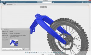
solidworks-2014-quick-mate-pop-up
New Quick Mate pop-up below the context toolbar

Just what constitutes an improvement in an established product line? Is a marginal increase in performance of 6%, for example, impressive enough? To an engineer—maybe. If that improvement translates into 5 more hours to devote to other tasks, then that could be a huge gain. The ability to manage data less and accomplish more can be seen as another terrific gain.

After all the opinions have been written and posted, it will be users who indicate whether these improvements are good, or good enough. SolidWorks is a bit like Rockwell Automation—”no one ever got fired for choosing Rockwell,” goes the saying.

SolidWorks 2014 includes 3D CAD, Simulation, Product Data Management, Technical Communication, and Electrical Design functions that further your ability to design with fewer limits. Some of the new enhancements promise to help you re-use data more dynamically, expediting the sharing of design data to accelerate collaboration.

This version also includes mobility support for Android and iOS devices, making it easier to connect and experience your 3D designs anywhere and anytime.

To maintain customer satisfaction, it is becoming increasingly important to save and track multiple versions and iterations of a design; customers want custom variations of a design, customers want the third version rather than the latest, manufacturing personnel need to examine an earlier version for assembly information, and so on. New features like the ‘history tab’ allow multiple users to see and track recent design changes with the click of a mouse. Enhanced features such as assembly mates, known as ‘common mates’ in the context menu, offer intelligent choices based on previous usage patterns and apply new options that make sense while performing assemblies.

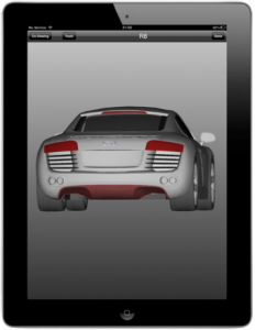
In other developments, Dassault Systèmes engineers are developing tools for Solidworks that work with 3D printing needs. With eDrawings, for example, you can view 3D designs and demonstrate how products behave in the real world through an Augmented Reality 3DExperience on any iOS device, such as an iPad or iPhone.

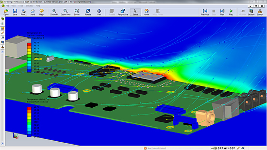
solidworks-2014-edrawings
Easily review multiple flow results in a single eDrawings file.

Other new tools and enhancements increase productivity across four key areas: design tools, integrated workflows, performance increases and enhanced visualization.

In Design Tools, three key tools are Advanced Shape Control, Fast Drawing Detailing, and Sheet metal features.

For the Advanced Shape Control feature, a new Style Spline function, automatic Sketch Picture scaling and Conic Fillet controls let you create complex surfaces and organic shapes faster, easier and with more precision.

solidworks-2014-curvature-combs
The Curvature Combs of a Style Spline reveal smooth curvature and transitions with minimal inflection.

Improvements to Faster Drawing Detailing deliver faster and more automated drawing detailing.

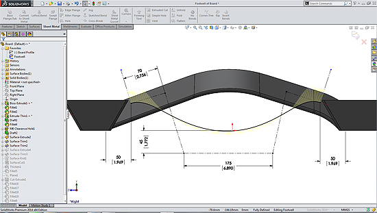
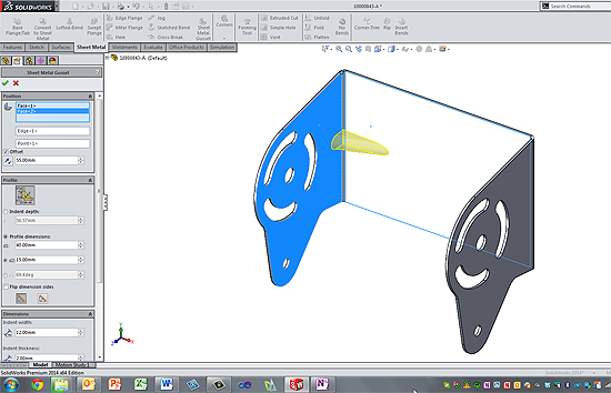
New sheet metal features enable faster creation of sheet metal geometry and improved data output for manufacturing. You gain improved control over corner treatments, for example, as well as the ability to create stiffening ribs such as the indented design seen on mounting brackets used to reinforce the weight and force placed on the part.

solidworks-2014-corner-gusset
A Corner Gusset is added across a sheet metal flange. A full preview is available making it easy to visualize on creation.

Changes to better integrate workflows, reduce the amount of time needed to manage data across features and platforms include:

  • SolidWorks Enterprise PDM Streamlined Workflow, which helps manage more data using the new Microsoft Office integration and enhanced Web Client with graphical preview features.
  • SolidWorks Electrical Improved Integration and Performance has been enhanced to deliver better integration with SolidWorks Enterprise PDM and eDrawings to optimize, share and track electrical designs more easily.

Now, you can choose to view your designs on other mobile devises, such as Android, with Design Communication and Collaboration.

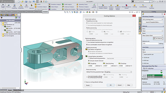
You can cost parts faster with less setup, with then share cost data more effectively with Streamlined Cost Estimating and Reporting. For example, key product development data for assembly can now be sent to Microsoft Excel allowing for easy sharing with departments such as manufacturing and purchasing.

Visualization has been improved with Streamlined Simulation Setup, which automatically leverages engineering data for re-use in simulations, eliminating duplication of effort and improving design collaboration.

And with Enhanced Assembly Performance and Visualization, you can create assemblies faster and easier with the new in-context Quick Mate tool bar and Slot Mate. For assembly in section views, you can include or exclude selected components allowing for a fast creation of more impressive section views.

SolidWorks, Dassault Systèmes
www.solidworks.com

Filed Under: 3D CAD Package Tips, CAD Blogs, CAD Industry News, CAD Package, CAE, Company News, SolidWorks, SolidWorks Blogs, SolidWorks News & Events Tagged With: SolidWorks

Guitar maker speeds design process

January 19, 2012 By Laura Carrabine Leave a Comment

Fender Musical Instruments Corporation is a leading manufacturer of stringed instruments, including electric, acoustic, and bass guitars as well as guitar amplifiers. While the company handcrafted guitars and used 2D AutoCAD design tools for many years, the 2002 acquisition of the JACKSON guitar brand brought more complex geometry challenges that required 3D design technology to drive manufacturing.

Fender chose SolidWorks CAD software – first deployed on the JACKSON and FENDER STRATOCASTER lines and now used companywide – because it is easy to use, includes advanced surfacing capabilities, and integrates well with CAM applications. By deploying SolidWorks, Fender cut production time by 20% across the board, reduced the time required to shape guitar necks by 30%, eliminated many secondary operations, and increased production throughput with improved tooling.


SolidWorks

www.solidworks.com

Filed Under: 3D CAD Package Tips, CAD Blogs, CAD Package, SolidWorks, SolidWorks Blogs, SolidWorks News & Events Tagged With: 2D, 3D CAD, AutoCAD, Fender Guitar, SolidWorks

New software slated to change the workplace

January 3, 2012 By Laura Carrabine Leave a Comment

CAD software vendors have touted product usability for a long time. However, they haven’t really delivered on that promise until recently. There were a few software debuts in 2011 that changed that premise. True user usability could lead to a broader CAD audience and a bigger market share.

The product development team at PTC came up with the idea of a creating single program that does everything versus offering diverse programs with no connectedness. The strategy addresses its customer base and the trend toward solid modeling for the masses. Creo 1.0 is the result of that concept. The software currently has nine applications including Creo Parametric, Direct, Illustrate, Schematics, View MCAD, View ECAD, Sketch, and Layout.

The company focused on a group of traditional user problems and applied a core of technologies against them, specific roles having options for modeling modes with the click of an app. Simplifying a process that has plagued engineers and designers for decades makes using the software and being productive all the difference. The Creo GUI is much cleaner than the Pro/E GUI. According to those who have used the new product, the GUI strategy is most evident in Creo Parametric and Creo Direct. PTC leveraged the best features from CoCreate and made it easier to use. The company added features to Creo Parametric that will make Pro/E seem like ancient technology. Creo proves that a feature can live in a history-based and history-free environment keeping the parametric relation to features within each if needed.

Another 2011 debut was SolidWorks 2012 that also sports new features to help a more diverse audience. The software has improvements in assembly and drawing capabilities, built-in simulation, design costing, routing, image and animation creation, and product data management. Dassault Systemes says SolidWorks 2012 will help automate design functions, change product development processes, and extend support for collaboration and connectivity. This technology could change how the software is marketed and sold. The product helps users streamline design processes by removing traditional steps.

Autodesk’s AutoCAD 2012 and Design Suite 2012 series are available in a range of offerings including web and mobile applications. Thus more users have access to the technology and can stay connected to their work no matter where they are.  In addition, AutoCAD 2012 and Design Suite 201212 are directly connected to the free AutoCAD WS web and mobility application.

With CAD pretty much saturating the engineering and manufacturing arena, CAD vendors are realizing that pumping out a redressed version of what went out the door at the last launch is not going to work much longer. They have to offer tools that appeal to other audiences. We have seen that starting to happen in the retail, hobby, and jewelry industries where non-engineering types are using 3D programs to crank out new products.

PTC
www.ptc.com

Dassault Systemes
www.3ds.com

Autodesk
www.autodesk.com

Filed Under: Autocad Blogs, Autodesk, Autodesk News, Catia, Catia Blogs, Catia News & Events, PTC News, SolidWorks, SolidWorks Blogs, SolidWorks News & Events Tagged With: 3D CAD, AutoCAD, Autodesk, Catia, Design Suite, PTC Creo, SolidWorks

Recreated USS Missouri

December 13, 2011 By Laura Carrabine Leave a Comment

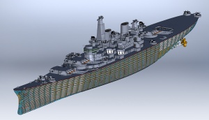
SolidWorks user Donn McKinney’s dream is to construct a Hollywood-quality fleet of battleships for museums and ports. He is part of a team engaged in producing operational replicas of the Iowa Class Battleships USS Iowa, USS New Jersey, USS Missouri, and USS Wisconsin. The goal of the project is tto put these ships on display for education and enjoyment of the general public in various venues.

“Battleships like the Missouri bring waves of emotion to people. Seeing tese floating parts of history conjures memories of sadness, joy, and wonder, “ said McKinney. “My goal is to bring living history to those people and cities who feel connected to these now almost mythical ships.”

Through advancements in SolidWorks software, McKinney has seen his project evolve from an 18-ft wooden ship, to an 18-ft steel ship. More recently, the latest rendition of the project is a 28-ft replica that features the ship’s complete functionality including radar and fully operational scaled weapons. McKinney is also adding a system that will allow presenters to give full military orders to the vessel and receive an immediate response.

“When these ships were first built, they were termed as “the most complicated moving man-made objects on Earth. Indeed, they were and continue to stand as great feats of engineering, said McKinney. “Thanks to SolidWorks, I am creating complex ships with ease and ensuring the replicas are truly authentic by using the state-of-the-art technology.”

He is adamant that any ship can be created using this methodology including the USS Arizona, the French Battleship Richlieu, and the British Battleship HMS Hood among others.

SolidWorks

www.solidworks.com

Filed Under: 3D CAD Package Tips, SolidWorks, SolidWorks Blogs, SolidWorks News & Events Tagged With: 3D CAD, Dassault, SolidWorks, USS Missouri

AAC Engineered Systems

December 7, 2011 By Laura Carrabine Leave a Comment

The company focuses on heavy-duty applications and advanced material handling. The company was using a 2D design package and decided to move to a 3D CAD system to gain greater flexibility in designing equipment to meet customer requirements.

AAC’s engineers attended the Chicago Machine Design Show and reviewed every CAD system being demonstrated. They were most impressed with SolidWorks because it is based on mechanical design

According to a company spokesperson, “SolidWorks software has revolutionized our engineering department. Configuration Management enables us to reuse existing designs in creating custom-made equipment. We try out different “what-if” configurations, checking for interferences and fit-on-screen, not on the production floor. Smart Part Technology knows which fasteners go into which holes and puts them there. We can design sheet-metal parts accurately without first machining them, saving time and reducing scrap. Our designers create the models, and SolidWorks makes the drawings, allowing us to conserve technical resources. And, eDrawings helps us market to and communicate with customers.”

SolidWorks

www.solidworks.com

Filed Under: 3D CAD Package Tips, CAD Industry News, SolidWorks, SolidWorks Blogs, SolidWorks News & Events Tagged With: 2D, 3D, AAC Engineered Systems, cad, Configuration Management, eDrawings, Smart Part Technology, SolidWorks

Orange County Choppers

September 29, 2011 By Laura Carrabine 1 Comment

Orange County Choppers (OCC) started designing and building custom motorcycles in 1999. The company selected SolidWorks Premium software as its standard design platform because it is easy to use, includes visualization and surfacing tools, and integrates well with MasterCAM software which automates machining on the company’s HAAS CNC production systems.


“Every bike we build is a 100% custom design,” said OCC senior designer Jason Pohl. “With SolidWorks, we can refine the design and then control the production of parts with a high degree of precision. SolidWorks has become the backbone of our development effort because everything revolves around the SolidWorks model.”

Instead of trying out different concepts in the shop using actual prototypes, the company now iterates on designs in the SolidWorks design environment, which is more efficient and cost-effective. Since implementing the software, OCC has accelerated its time-to-market by 100%, cut design cycles by 75%, and eliminated several rounds of prototyping.

OCC can now efficiently handle the increased volume of orders it now receives, both in development and during production. SolidWorks support for automated machining boosts throughput and because manufacturing from a solid model is more accurate, OCC is able to keep its costs down. Since implementing SolidWorks, the custom motorcycle manufacturer has cut development costs by 50%.

Pohl added, “Whether we’re working with an outside vendor or in our own machine shop, SolidWorks makes it easier to efficiently create usable parts. In my experience, 2D techniques hide flaws. 3D design reveals flaws. When it’s time to manufacture a part, the software enables us to have confidence that the model is right. That makes our lives a whole lot easier.” 

SolidWorks also helps OCC interact more efficiently with customers, who often want to see how the motorcycle will look before placing an order, especially for a growing number of corporate bikes. Using the software’s visualization and communication tools such as PhotoView 360, OCC can show high-quality renderings of custom motorcycle designs to clients.

SolidWorks

www.solidworks.com

Orange County Choppers

www.orangecountychoppers.com

Filed Under: 3D CAD Package Tips, CAD Industry News, SolidWorks, SolidWorks Blogs Tagged With: 3D CAD, CNC, Orange County Choppers, PhotoView 360, SolidWorks

SolidWorks models on an iPad

September 14, 2011 By Laura Carrabine Leave a Comment

CadFaster, the simple, free application for collaborating on SolidWorks 3D models is now available on the iPad App Store. CadFaster lets you access your projects on the move and allows your whole team to markup and co-view models in real time.

You can export models as EXE files for Windows users and to cloud service for iPad users. You can also manipulate models to create unique views. Measure accurately on the iPad. Markups are accessible for everyone in real time.

CadFaster

www.cadfaster.com

Filed Under: 3D CAD Package Tips, CAD Package, SolidWorks, SolidWorks Blogs Tagged With: 3D CAD, CadFaster, cloud, iPad, SolidWorks

20th release of SolidWorks wins kudos

September 7, 2011 By Laura Carrabine Leave a Comment

There are new drawing tools to help create better looking and more accurate images. For example, changed dimensions are automatically highlighted and show previous values to help with revisions. Sequential balloon ordering and magnetic lines automatically help order and position balloons. So you may not have to spend as much time detailing and aligning drawings.

SolidWorks’ Sustainability’s new user interface can be used to more accurately model products with “what-if” scenarios and custom materials. Users can model processes with parameters such as recycled content and duration of use. Access to the latest Sustainability supplemental materials will be instant and continuous as they become available.

The large design review allows instant opening and review of large assemblies or any individual component with walkthroughs, sectioning, and measuring without the need for a high-powered computer or special file preparation. The freeze feature eliminates unwanted feature rebuilds by locking all features above the “freeze” bar. This option can help speed up the design of complex models where rebuilding specific features is not needed. Features can also be unfrozen at any time. There are also new equation capabilities that speed up the calculation process.

Design costing is a tool that automates manufacturing cost calculations for sheet metal and machined parts. Designers can make more informed decisions based on cost throughout the design process and continually model new scenarios for instant up-to-the-minute manufacturing estimates. SolidWorks 2012 offers new sheet metal tools such as precise control of edge flanges, including up-to-vertex end conditions. Designs can be flattened and documented for manufacturing with export to CNC and manufacturing equipment.

SolidWorks Simulation includes enhanced motion optimization that automatically uses motion study results to create sensors and refine complex and time-intensive machine aspects such as motor size, bearing loads, and range of travel. Users can optimize designs quickly as they refine inputs and immediately see changes to restraints or goals.

SolidWorks Enterprise PDM has new support for Office 2010 and an x64 web client. In addition, there are enhancements to 3DVIA Composer including part-to-part shadows, ambient occlusion, and shadows to 2D panels with precise control. A glow effect can also be added to highlight specific areas of interest.

SolidWorks

www.solidworks.com

Filed Under: 3D CAD Package Tips, CAD Blogs, CAD Package, SolidWorks, SolidWorks Blogs, SolidWorks News & Events Tagged With: 3D CAD, 3DVIA Composer, CNC, Dassault, drawings, PDM, sheet metal, SolidWorks

  • Go to page 1
  • Go to page 2
  • Go to Next Page »

Primary Sidebar

3D CAD NEWSLETTERS

MakePartsFast

Follow us on Twitter

Tweets by 3DCADWorld

Footer

3D CAD World logo

DESIGN WORLD NETWORK

Design World Online
The Robot Report
Coupling Tips
Motion Control Tips
Linear Motion Tips
Bearing Tips

3D CAD WORLD

  • Subscribe to our newsletter
  • Advertise with us
  • Contact us
Follow us on Twitter Add us on Facebook Add us on LinkedIn Add us on Instagram Add us on YouTube

3D CAD World - Copyright © 2021 · WTWH Media LLC and its licensors. All rights reserved.
The material on this site may not be reproduced, distributed, transmitted, cached or otherwise used, except with the prior written permission of WTWH Media.

Privacy Policy