• Skip to primary navigation
  • Skip to main content
  • Skip to primary sidebar
  • Skip to footer

3D CAD World

Over 50,000 3D CAD Tips & Tutorials. 3D CAD News by applications and CAD industry news.

  • 3D CAD Package Tips
    • Alibre
    • Autodesk
    • Catia
    • Creo
    • Inventor
    • Onshape
    • Pro/Engineer
    • Siemens PLM
    • SolidWorks
    • SpaceClaim
  • CAD Hardware
  • CAD Industry News
    • Company News
      • Autodesk News
      • Catia News & Events
      • PTC News
      • Siemens PLM & Events
      • SolidWorks News & Events
      • SpaceClaim News
    • Rapid Prototyping
    • Simulation Software
  • Prototype Parts
  • User Forums
    • MCAD Central
    • 3D CAD Forums
    • Engineering Exchange
  • CAD Resources
    • 3D CAD Models
  • Videos

concept design

PTC Releases Creo Elements/Direct v19.0

June 18, 2014 By Barb Schmitz Leave a Comment

Another announcement made at this year’s PTC Live Global event was the release of PTC Creo Elements/Direct 19.0, direct modeling software that now includes productivity enhancements in modeling, drafting, collaboration and data management. As mentioned in the Creo 3.0 blog, the company also unveiled new technology it’s calling Unite technology that better supports multi-CAD environments.

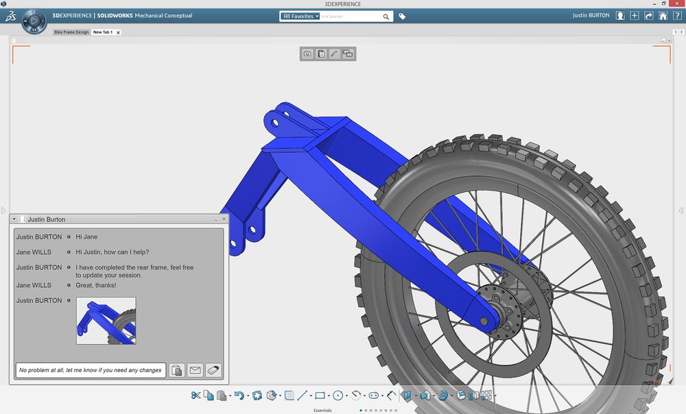
Collaboration seems to remain a tricky task for distributed design teams juggling format in multiple CAD file formats. The Unite technology will enable users to open native CAD files created in other popular CAD formats, and then save, edit and share that data with others. The response from users attending the event was unanimously favorable.

“The new import capabilities in PTC Creo Elements/Direct 19.0, formerly known as CoCreate, will allow us to collaborate more effectively with companies using different CAD tools,” said Nobuaki Sugimoto, mechanical designer, Icom, Inc.

PTC Creo Elements/Direct 19 now offers support for multi-CAD environments, via Unite technology

Enhancements to Creo Elements/Direct include:

* Support for Multi-CAD Collaboration. Support for direct import of SOLIDWORKS and Autodesk Inventor data enables teams to quickly and easily incorporate design information without the need for additional software. Upward compatibility with PTC Creo is also significantly enhanced.

* Optimized Design Workflows. Higher productivity is enabled through optimized design workflows for a variety of regularly used features, and the introduction of template-based drawing creation significantly reduces redundant effort by enabling the re-use of existing drawings as a starting point.

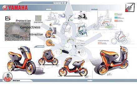
* New Concept Design Capabilities. Concept design is made easier with the introduction of new 2D and 3D tools including support for the use of 2D images in concept development, a palette of pre-defined 2D shapes and new curve creation commands.

* New Sheet Metal Capabilities. New capabilities in the sheet metal module allow the creation of fully valid, un-foldable sheet metal parts that represent a transition between two parallel profiles.

* Scalable Data Management. Through core infrastructural improvements, PTC Creo Elements/Direct Model Manager delivers greater scalability for large deployments.

For a more extensive list of new enhancements to Creo Elements/Direct 19.0, click here.

Filed Under: Creo, News, PTC/CoCreate Blogs Tagged With: concept design, data management, Direct Modeling, sheet metal design

Debating the Most Efficient Way to Go from Concept to Documentation

April 15, 2014 By Barb Schmitz Leave a Comment

The conceptual phase of design is the only one within the product development window that must be inherently fluid, and in a sense, should be done in a leisurely manner. What, you ask? The word “leisure” is probably not used often when it comes to designing products, right? OK, let me explain.

In order to fully evaluate a suitable number of potential design concepts, engineers and designers must have the luxury of time. After all, how can you determine an optimum solution until you’ve discounted an adequate number of bogus ones? Unfortunately, not many of them get that time.

According to a conceptual design study conducted by PTC, 92% of respondents felt that their product development process would benefit tremendously from the ability to evaluate more concept ideas before moving forward into detailed design and documentation. Another 61% said that the concept design process is often cut short to due schedule constraints.

Time, after all, is critical to meeting design production schedules and shipping products on time. It’s the underlying reality of all those involved with product development.

This concept design for Yamaha was created by a Alberto Agnari. It included concept boards, sketches and traditional and digital renderings.

Which route to take: direct or feature-based?

Once a concept design has been approved and moved forward, time is of the essence. During our “The Pros and Cons of 3D Modeling Paradigms” webinar, one of the questions posed to our panel of speakers was in regards to what modeling paradigm is best in terms of time efficiency when moving from the concept stage to the documentation state, keeping in mind that a good percentage of the dimensions can be automatically generated within the history-based model. The answers were surprising and I thought worth sharing.

Dan Staples, vice president, Solid Edge Product Development, Siemens PLM Software

In a history-based system the dimensions are in the sketches and then those are retrieved into the drawing. In a direct modeling system, or at least in Solid Edge, the dimensions take the form of what we call PMI (product manufacturing information) or the 3D dimensions that are on the faces of the model instead of in the sketches. That doesn’t change the ability to retreat those into the drawing. The fact is that they’re on the faces instead of the sketches, same thing in terms of ability to retrieve those that are in the drawing and use them.

Brian Thompson, vice president of Creo Product Management, PTC

Yeah, I think if you have good workflows for creating or showing those dimensions in the 2D context, it could be similar in terms of efficiency to do either. I don’t see one modeling paradigm strongly standing out. There’s good efficient workflows for creating dimensions on models that have no underlying sketches, and there’s good workflows for showing them on models that do. As Dan and I have said, dimensions in the direct modeling environment can, in fact, still drive geometry if the user tells the system that’s what he wants.

You can still even get that behavior. Maybe not to the level you would get with a large feature-based, history-based parametric model, but you could still get that behavior. There may be some circumstances where one is slightly better than the other, but I’d say it’s fairly close in terms of efficiency to create that documentation. Would you agree Dan?

Dan Staples

I would actually say it’s somewhat more efficient. One of the constraints we forget about is that when you build up a history-based model, you build it up sketch by sketch by sketch. That’s not necessarily a natural way to dimension the part. In fact, it’s pretty bad practice in terms of a dimensioning scheme because you tend to have a lot more dimensional stack ups than you would like. Whereas if you’re in a direct modeler, you can put in dimension between two faces on the model that are far from each and there’s 50 features in between, and so you can actually have a much more natural dimensioning scheme that’s more immediately usable in the drawing when you see direct models in my opinion.

Brian Thompson

Yeah, I think we’ll agree there that bad modeling technique and your history-based parametric modeling will make it even harder in the drawing to do that. If you got a good, well-done history tree then maybe it’s not as hard but it’s a good point.

The bottom line

Though it’s not easy to sum up all the good points here, its clear the most time-efficient way to move your designs from concept to documentation is to use best practices when it comes to how you model your products and good dimensioning workflows. In other words, the use of good modeling techniques will always get you from Point A to Point B faster, whether you’re working in a direct modeling or feature-based modeling 3D CAD system.

If you missed the “Pros and Cons of 3D Modeling Paradigms” webinar, you can watch it in its entirety here.

Barb Schmitz

Filed Under: 3D CAD Package Tips, Creo, Siemens PLM Tagged With: concept design, Creo, documentation, Solid Edge

Dassault Ships Mechanical Conceptual

April 3, 2014 By Barb Schmitz Leave a Comment

Though it was announced back in January at SolidWorks World, Dassault Systemes today announces that Mechanical Conceptual is now available. The first SolidWorks application on the 3DEXPERIENCE platform, Mechanical Conceptual has already been hard at work in production environments at numerous customer sites. Touted to be more social and conceptual, the software is expected to greatly facilitate design collaboration among key design contributors through its use of Dassault’s cloud-based capabilities.

Here’s what one of the SolidWorks resellers is saying about the new product. “Now that the majority of the companies we partner with have embraced cloud technologies, GoEngineer has seen a dramatic increase in requests from our customer’s engineering, design, and manufacturing departments for help in leveraging the cloud in their organizations. We are excited to offer them SOLIDWORKS Mechanical Conceptual as a solution that effectively combines the benefits of cloud, integrates the amazing power of social technologies, and addresses the need for some design teams to have preliminary layouts before finalizing their CAD work.” said Brad Hansen, CEO of GoEngineer.

Mechanical Conceptual will help key design participants collaborate on designs early and throughout  the design cycle.
Mechanical Conceptual will help key design participants collaborate on designs early and throughout the design cycle.

Working in tandem with the regularly updated SolidWorks 3D mechanical CAD software, SolidWorks Mechanical Conceptual allows customers to harness the collective intelligence of the entire design team, customers and the supply chain to capture ideas, leverage existing designs, collaborate and quickly collect feedback. Customers have the ability to purchase what best supports their specific conceptual design process:

* SolidWorks Mechanical Conceptual – an instinctive powerful 3D modeling environment with online data storage and social collaboration on Dassault Systèmes’ 3DEXPERIENCE platform.

* Collaborative Sharing – additional access for non-CAD users (executives, design team leaders, project managers and external collaborators) who need to manage data on the cloud and collaborate without constraints, but do not need to create CAD models.

* Product Design Simulation from SIMULIA – easy-to-use simulation-based guidance during all phases of product design, including the critical conceptual design stage, to improve product performance and reduce cost.

Customers can buy Mechanical Conceptual through SolidWorks’ reseller partners. More information of Mechanical Conceptual can be found here.

Barb Schmitz

Filed Under: 3D CAD Package Tips, SolidWorks, SolidWorks Blogs Tagged With: Collaboration, concept design, SolidWorks

Which 3D Modeling Tools are Best to Use For Concept Design?

March 17, 2014 By Barb Schmitz Leave a Comment

In today’s highly competitive markets, the ability of a manufacturer to develop successful, innovative products often hinges on how well it fosters, fleshes out and evolves new ideas and concepts into new products. The problem with this conceptual design phase of development is that engineers and designers often struggle with what tools are best to use.

They need highly flexible tools that enable them to freely explore myriad of design alternatives and don’t lock them into too much detail before a sufficient number of ideas have been explored. However, they also need a way of accurately tracking and recording these ideas so they can have something from which to work once an idea has been approved and moved forward.

Engineers still use multiple tools to capture concepts

PTC conducted a study, Trends in Concept Design, in which over half of participants (51%) said they capture design concepts and ideas electronically in the form of 3D data. The majority (61%) responded that they use 3D CAD modeling and surfacing tools to quickly create a multitude of potential product designs.

The use of multiple tools from multiple vendors often complicates the process of concept design and creates problems downstream when concept models move to detailed design. According to the PTC survey, participants who used multiple tools from different software vendors during the concept phase of new product development were three to seven times more likely to have to recreate data due to incompatibility.

Concept design is an extremely vital phase of product development. Tools  used must be fluid and flexible so an adequate number of design ideas are explored. Image courtesy of Teams Design.
Concept design is an extremely vital phase of product development. Tools used must be fluid and flexible so an adequate number of design ideas are explored. Image courtesy of Teams Design.

Which 3D tools should be used?

During the “The Pros and Cons of 3D Modeling Paradigms” webinar, Creo Product Management VP Brian Thompson’s presentation included some of the survey’s results. The following question was posed to our panel of experts in regards to concept development: “The survey said that most companies what to reuse concept designs in detailed design stage. Wouldn’t that always prohibit using direct modeling in the concept stage?”

“No, it doesn’t,” says Thompson. “You can impart design intent on a model that’s largely history-free and still control certain key aspects of that model with constraints and with other types of technologies. What we’re finding is that customers can, in fact, mature designs from 3D that have no history–whether they came in from a third party or they were using strict direct modeling from the front end–and mature them into real production models down the path without having to recreate that model from scratch using history-based designs.

Both Siemens and PTC have thousands of customers that rely solely on direct modeling every day for everything they do. It can be very, very simple products or very, very complex highly engineered products with tens of thousands of parts in the assembly. There really is no limit, it’s all a matter of the company deciding what set of tools suit their needs best.”

Taking the “direct” route to concept design

The direct modeling paradigm enables engineers to create new concepts based on previous designs. Users can start with a 2D concept model and easily use it as the basis of a 3D model. Direct modeling tools also enable concept designers to leverage all types of available legacy data, including 2D drawings, sketches, surfaces, single parts, or entire assemblies without data interoperability issues.

Perhaps the biggest benefit is the time savings afforded by direct modeling tools. Because these direct modeling tools offer interoperability with parametric, feature-based modelers used for detailed design, no model recreation is necessary, giving designers more time to explore a wider range of design alternatives.

If you missed the “Pros and Cons of 3D Modeling Paradigms” webinar, you can watch it here in its entirety.

Barb Schmitz

Filed Under: News Tagged With: 3D modeling, concept design, PTC, Siemens

Looking Under the Hood of SketchUp 2014

March 4, 2014 By Barb Schmitz Leave a Comment

Engineers and designers have always struggled with which design tools are best to use to capture concepts during the early conceptual phase of product development. The concept design is one of the most important phases of the entire product development process.

It is here when new product ideas are tossed around, flushed out, vetted, discussed, tested, refined and eventually pushed forward to detailed design. It is also here where most (60%-75%) of total product development costs are committed; making it very costly to make significant changes after this phase is completed.

The tools used in this phase must be flexible and intuitive so users feel free to explore options, wander about, and make mistakes. After all, making mistakes at this stage can actually lead to better designs later. Feature-based 3D modeling tools, which powerful, often force users to lock into design ideas prematurely. For this reason, many users prefer using simpler 2D tools for capturing concepts.

Other engineers still prefer to sketch out design ideas on paper or in engineering notebooks. While this might sound archaic in today’s high-tech world, it opens up the design exploration process to everyone and encourages rapid-fire idea generation without fear of mistakes. The downside is that these budding concepts can’t be changed easily, preventing ideas from benefitting from collaborative feedback and possibly evolving into even better ideas.

SketchUp provides the best of both worlds: flexibility and ease of use

While SketchUp is very popular in the architectural design community, this tool is also being used by engineers and designers to quickly create 3D models of product concepts. Originally developed and released by Google in 2000, SketchUp’s popularity stems from the fact that it’s easy to use, powerful, and free.

While the tool is popular for creating architectural models, this 3D car model was created by DeviantArt using SketchUp.

Last year the company that now develops SketchUp, Trimble Buildings, reported that the product had more than 30 million unique activations in the last year, making it the most widely used 3D modeling software in the world.

New features in SketchUp 2014

The new release introduces major enhancements to SketchUp’s 3D Warehouse, the world’s largest repository of free, high-quality, 3D content. Other new features include new tools that improve the classification of design objects, tighten interoperability with other products used in building information modeling (BIM) workflows, and 2D documentation improvements.

SketchUp’s 3D Warehouse is an online repository for finding, storing and sharing useful 3D models. In SketchUp 2014, the 3D Warehouse has been rebuilt, making it easier for users to quickly find the models they need, create and organize their own collections, and share them.

* The new 3D Warehouse now features an integrated WebGL viewer, enabling users to preview and orbit models in full 3D before downloading them into their own projects.
* Users can now upload 3D models directly from their Web browsers, without first opening them in SketchUp, while the maximum size of uploadable models has been increased from 10 to 50 megabytes.
* The new product catalogs feature speeds the task of finding specific manufacturers’ products, letting users start their models with the exact items they intend to use.

The new release marks Trimble’s second major update to SketchUp software in the past 10 months and reinforces the company’s commitment to continuously improve SketchUp with easier ways to create, access, share and collaborate on 2D drawings and 3D models. SketchUp Pro, designed for professional users, costs $595.

For a more extensive explanation of all the new bells and whistles of SketchUp 2014, go here.

Barb Schmitz

Filed Under: CAD Blogs, General Blogs, News Tagged With: concept design, Google, SketchUp

Primary Sidebar

3D CAD NEWSLETTERS

MakePartsFast

Footer

3D CAD World logo

DESIGN WORLD NETWORK

Design World Online
The Robot Report
Coupling Tips
Motion Control Tips
Linear Motion Tips
Bearing Tips

3D CAD WORLD

  • Subscribe to our newsletter
  • Advertise with us
  • Contact us
Follow us on Twitter Add us on Facebook Add us on LinkedIn Add us on Instagram Add us on YouTube

3D CAD World - Copyright © 2022 · WTWH Media LLC and its licensors. All rights reserved.
The material on this site may not be reproduced, distributed, transmitted, cached or otherwise used, except with the prior written permission of WTWH Media.

Privacy Policy