• Skip to primary navigation
  • Skip to main content
  • Skip to primary sidebar
  • Skip to footer

3D CAD World

Over 50,000 3D CAD Tips & Tutorials. 3D CAD News by applications and CAD industry news.

  • 3D CAD Package Tips
    • Alibre
    • Autodesk
    • Catia
    • Creo
    • Inventor
    • Onshape
    • Pro/Engineer
    • Siemens PLM
    • SolidWorks
    • SpaceClaim
  • CAD Hardware
  • CAD Industry News
    • Company News
      • Autodesk News
      • Catia News & Events
      • PTC News
      • Siemens PLM & Events
      • SolidWorks News & Events
      • SpaceClaim News
    • Rapid Prototyping
    • Simulation Software
  • Prototype Parts
  • User Forums
    • MCAD Central
    • 3D CAD Forums
    • Engineering Exchange
  • CAD Resources
    • 3D CAD Models
  • Videos

3D CAD

Are Engineering Drawings Dead?

August 26, 2014 By Barb Schmitz Leave a Comment

Mark Twain once famously said, “The reports of my death have been greatly exaggerated.” If engineering drawings collectively had a voice, they might say the same thing. With product developers increasingly transitioning to 3D CAD systems, many have predicted that engineering drawings would go the way of landlines, printed maps and VCRs.

Engineers–once better known as draftsmen–spent decades perfecting the precision needed to create 2D drawings that represented engineering designs in the most accurate and concise manner possible. For those who spent considerable time learning this skill, the question is why drawings need to be abandoned.

With all the advancements in 3D CAD, are engineering drawings going to eventually be obselete?

Is 3D better?

There are many compelling reasons why designing in 3D is better, both in terms of overall efficiencies and resulting product quality. Perhaps the biggest advantage is how quickly changes can be made, removing the time-consuming and error-prone process of making changes to multiple drawing views every time an engineering change order (ECO) comes down the pipe.

Downstream processes also benefit when 3D product data is shared to create all the supporting product collateral and documentation. No longer are technical illustrations created manually. Sales and marketing can create supporting collateral to seed the market in advance of products being manufacturing. The list of benefits go on and on.

I came across an interesting post written by Ed Lopategui on the GrabCAD site entitled “Engineering Drawings are Dead” that discusses engineering documentation and its inherent limitations. Part of the reason why he believes that product development is moving beyond 2D drawings is the growing momentum behind Model-Based Engineering (MBE) initiative and the importance of sharing Product Manufacturing Information (PMI).

According to Lopategui, the shortcomings of engineering drawings include:

* Interpretation Issues: A properly executed drawing shouldn’t be subject to misinterpretation, but that skill is starting to become something of a lost art. Unclear depictions can be problematic (i.e. which surface did that leader line touch?). More disturbingly, errors can easily escape detection. Sure, most of that can be mitigated with carefully defined GD&T, but that too seems to be a fading skill. PMI improves upon these limitations by clearly associating surfaces and endpoints, and providing validation that such dimensions do indeed make logical sense.

* Manual Inspection: Drawings necessitate reinterpretation by humans on the other side of the manufacturing lifecycle. It’s another way to introduce error: the botched inspection. PMI sets the stage for automated inspection, accelerating manufacturing processes while simultaneously improving quality.

* Time is Money: This is where drawings go for the BRAINS… Simply put, in today’s constantly accelerating demand to crank out the engineering in less time, drawings just take too long. Increased market pace demands more efficient processes. An engineer who’s spent considerable time defining a model, shouldn’t have to spend much longer documenting it. The days of modeling something then throwing it over a fence to lay it out are over. These two aspects of design must occur simultaneously, and this ultimately is only possible with model-based definition.

Despite this list of limitations, engineering drawings live on. According to Lopategui, part of the reason is that traditional drawings are universally accessible, as opposed to 3D visualization and inspection tools still not commonly seen on manufacturing floors. Largely proprietary 3D PMI storage formats are also helping propitiate the continued legacy of drawings.

Read the entire “Engineering Drawings are Dead” post here. The blog generated a lot of comments on CADCAM Technology Leaders Group page on LinkedIn, many of which I thought were worth sharing.

Let’s take a look at some of the comments:

Joe Sanders, Applications Engineer / Manufacturing Specialist at M2 Technologies

For product design, I’d agree that the “engineering drawing” is not necessary, but what about the information that the manufacturing, inspection and assembly departments need for their role in turning the product concept into reality? How will these people gather the information that they need simply from a solid model? Until the major CAD vendors include GT&T, part finish and other critical information in the solid, the advocates of paperless design are suggesting a vision of a future world and not a present reality.

The major CAD vendors currently offer ability to store a great deal of useful information (such as tolerance, finish, etc.) in the solid model during the design process. We can’t get to that entire rich set of data yet in downstream software applications, such as CAM, without opening up the solid model in the native CAD software in which it was designed. That is why “inspection drawings” are still very much needed. Which CAD vendor will be first to the market with the SDK providing any downstream application to access the entire solid model information simply by opening the solid?

Bill Biddle, Scientific Machinist at Howard Hughes Medical Institute

I am all for milling to the solid model and like to work this way but will still need some clarification on some features for fit, form and function to make a useable part. So how do you get the information from the solid part file to the person actually making the part without having the native software the part was created in? Most shops big and small have operators cranking out parts. Do they just run them blind and rely on QC to catch mistakes? Does QC that has a CMM inspect the part to the model? What about critical sizes and tolerances? What if QC does not have a fancy high dollar CNC CMM that can inspect to the model? This all seems like a fantasy and theory. The $85k 3D inspection arm we purchased last year sounded good in theory, but has been collecting dust because real world won out over theory. It all sounds good but in reality it does not seem to be able to stand up and hold its ground.

This will increase the cost of production by pushing off work done by engineers and draftsman down the road to those making the parts, especially in a small quantity job shop environment. If all of the information is included in the 3D part file, tolerances, finishes and so on, then the engineer has likely spent the same amount of time as doing this as they would making a critical dimensioned drawing. Then how has this “new” way any different that the old way other that it’s all electronic? Seems to have way too many what if’s to become a way of the future. For now anyway.

Seth Lolli, Senior Manufacturing Engineer at Solar Turbines

It all comes down to proper MBD. If you can fully “detail” your 3D components with model-based definition then yes, no need for a drawing. You also have to take into account, as a company, how are you building parts? According to a 3D model or according to a 2D drawing? In short, engineers can cut corners if they can’t create geometry correctly or need to cut a corner to save time. If that happens, they can still call out the correct information on the 2D drawing. What I’m saying is that you can’t really pick or choose sometimes, you either create parts according to a drawing, or according to a 3D model with proper MBD (but both can be done).

Joe Walsh, CEO/Founder at intrinSIM LLC

The ability to obtain proper MBD is in its infancy and until proper MBD is readily available and mature drawings are still necessary for downstream usage. MBD may eventually negate the need for drawings but it is engineering and engineers we are dealing with – so even when proper MBD is available it will take years (probably decades before drawings really die). It is a lot like FORTRAN – declared dead by many decades before its real demise and if you look hard enough you will find “it’s not quite dead yet.”

Joe Brouwer, President at TECH-NET INC – CAD Evangelist

The problem with the industry, both with PLM and MBE, is they are trying to use the model as the authorizing document. Truly this is impossible. The model is dumb once it leaves the native CAD system. Yes, the PMI tries to solve the problem by putting dimensions and annotation in 3D space. I really don’t understand this. They are now including only overly complex GD&T feature control. No, dims at all.

So today, manufacturing has to review the part by scrutinizing the model itself. Where with an associated document, they would just over look the part and easily understand what is required. This is very simple and can be standardized. Just think who would be harmed by creating a standard?? It all starts with the major CAD vendors.

What’s your opinion on this topic? We’d love to hear your thoughts.

Barb Schmitz

Filed Under: News Tagged With: 3D CAD, engineering drawings, MBE, PMI

Leveraging the Value of 3D Design Data

August 18, 2014 By Barb Schmitz Leave a Comment

Software vendors spend a lot of time and money touting the value of 3D CAD software though most of the attention is paid to the actual design process. After all, this is where engineers and designers focus most of their efforts and where the innovative designs are conceived and realized through the use of 3D CAD software.

Ideas are proposed, explored, vetted, and flushed out during the important conceptual design phase. Then engineers take those evolving concepts and convert them into fully detailed geometry that will eventually be past to manufacturing.

Downstream benefits of 3D data

The use of 3D CAD software has provided tremendous benefits to the design phase of product development, but leveraging that resulting 3D design data elsewhere in the enterprise–and even outside of the corporate walls to partners and suppliers–is where a bounty of potential benefits awaits. Many companies have barely scratched the surface of realizing these downstream benefits of 3D data.

After all, it takes a village, or at least an entire enterprise, to successfully conceive, design, manufacture and get any new product to market. This somewhat Herculean effort requires the carefully coordinated efforts of multiple disciplines, which all play a critical role in the ultimate market success of any product.

While engineering and manufacturing play a starring role in the design-test-build phases of product development, other departments, such as marketing, sales, service quality, training, and technical documentation, also play heavily into the successful rollout and support of final products. These departments are often referred to as off the critical path, but their involvement is still critical.

Make it easier for non-technical users to create associative 2D and 3D product communication deliverable directly from your 3D CAD data using products, such as SolidWorks Composer shown here.
Make it easier for non-technical users to create associative 2D and 3D product communication deliverables directly from your 3D CAD data using products, such as SolidWorks Composer shown here.

Despite this, not all companies are taking advantage of leveraging CAD data to these important downstream design consumers. Let’s take a look at how downstream departments can leverage the use of 3D design data and what tasks can be done better by using it.

Better sales proposals. Create proposals that feature fully rendered 3D images and animations and you’ll get an edge on any competition still submitting bids in 2D. Creating proposals in 3D also helps potential customers understand the intricacies of your product.

Better sales tools. Help out your marketing department by providing them with 3D photorealistic renderings of products. Being able to create supporting collateral in advance using 3D CAD data enables marketers to seed the market to assess interest in a new product.

More effective training materials. Instructors can hit the ground running by tapping 3D CAD data to create the technical manuals and tutorials that will be used to help users understand how to ultimately use the product.

Assess maintenance issues. Regardless of how amazing and innovative a new product is, at some point it will be need to be serviced. Document field service procedures using 3D CAD data prior to manufacturing to access how easy or difficult it will be to service that product once built.

Create assembly instructions. Instead of manually creating assembly instructions based on cryptic 2D drawings, 3D assembly models can be quickly and easily “exploded” in 3D CAD to enable folks downstream to easily include these views of a product’s internal components in technical illustrations, assembly instructions and customer documentation.

Collaborate better. Design review teams today have expanded to include many non-technical members, including marketing and sales. Sharing a 3D model with which they can interact can help them understand how a product will function so they can add their input–without having to know how to use a 3D CAD system or interpret a 2D drawing.

The bottom line

The ability to share 3D data downstream with non-engineering departments can deliver significant bang for the buck by increasing productivity, optimizing workflows, and providing non-technical personnel with a voice in the development of new products in design reviews.

In order to realize these benefits, however, companies must educate, train and encourage these downstream design participants to use and understand the extended value of 3D CAD data and how they can use it to be more productive and better contribute to the success of future products.

Barb Schmitz

Filed Under: News Tagged With: 3D CAD, cad, composer, SolidWorks

TransMagic Facilitates 3D CAD Comparison with MagicCheck R2

July 2, 2014 By Barb Schmitz Leave a Comment

Dealing with the challenges of multi-CAD design environments has become a reality for nearly all product engineers and designers today. It’s nearly impossible to find a company that uses only one CAD system. Even those that do standardize on one system, chances are that they work with suppliers and partners who use a different system, making the ability to work with multi-CAD data vital to success in today’s product development environments.

Juggling CAD data in multiple formats is a headache. Because each system uses a proprietary underlying file format, translations must be done when moving data from one system to another. Opening up and working on a CAD model created in another systems almost always results in rework and wasted time. As a result, interoperability issues cost companies significantly, both in terms of lost productivity or in expensive third-party translation services.

MagicCheck software quickly opens all major 3D CAD formats, including point data, to compare against the source CAD model and analyze accuracy.

Easier model comparisons

When engineers and designers receive 3D CAD models created in other systems, they often need to evaluate where partners or suppliers have made changes. Determining what is different between models and where changes have been made either to parts or assemblies is not an easy task. Good news on that front from TransMagic, the developer of 3D multi-CAD interoperability software.

The company just released MagicCheck R2, a 3D geometric data comparison application. New features of the software include multi-body comparison, three-point move positioning and dynamic dimensioning.

MagicCheck’s new assembly comparison and dimension features will allow suppliers to instantly find even the smallest model and assembly changes in new data sets, dramatically improving the accuracy of quoting based on 3D CAD data. This feature also allows companies to easily document changes to downstream processes, such as NC toolpaths and QA inspection plans.

The MagicCheck R2 feature enhancements allow users greater control over 3D CAD data for more accurate and detailed comparison results. The multi-body compare capability enables advanced comparison of parts in multi-bodied assemblies.

Now users can manipulate the alignment of parts anywhere in space using the new three-point Move function for precise analysis. The dynamic dimensioning intuitively guides users to create professional-level dimensions on any 3D part or assembly, enabling companies to produce more accurate quotes and share precise model query data among teams.

Multi-core processing enables increased performance and faster model import speeds by allocating system processing across all available system cores instead of the standard process of using one core at a time.

The new dockable browser panes and upgraded visualization features allow users to customize their 3D model comparison environment to their requirements. Supporting numerous file formats, MagicCheck R2 includes updated file format support for CATIA, NX, Inventor and Parasolid. New formats introduced in R2 include DWG/DXF and SMLib.

For more on MagicCheck R2, click here.

Barb Schmitz

Filed Under: CAM, News Tagged With: 3D CAD, multi-CAD

PartMaker Releases 3D CAD for CAM Software

April 22, 2014 By Barb Schmitz Leave a Comment

Problems and errors often arise when 3D CAD models are moved into the manufacturing environment. For years the various software systems used in design and manufacturing spoke different languages so 3D CAD models often needed to be translated or dumbed down before being used as input by CAM software, which often resulted in errors on the shop floor.

Bridging the CAD-to-CAM divide

PartMaker, a division of Autodesk’s Delcam unit, hopes to change all that by creating 3D CAD modeling software that generates the 3D engineering data that precision part manufacturers need to be productive without cluttering their work flow with tools they don’t need or use.

PartMaker Modeling 2014 is 3D CAD for CAM software that provides users with the ability to create 3D solid models from scratch as well as repair and modify any 3D engineering data. Touted to be the most powerful 3D CAD system available alongside a production-oriented CAM product, this new version offers a unique radial cut wizard for creating cylindrically wrapped part features as well as improved direct modeling and feature recognition functionality.

PartMaker Modeling 2014 is a 3D modeling tool developed specifically for the needs of CNC machinists.

What’s new?

The new functionality in PartMaker Modeling 2014 was designed specifically for users that make parts on turn-mill centers and Swiss-type lathes as it includes a wide variety of functionality for creating milled features on parts that are cylindrical in nature.

Other new features include:

* Unique radial cut wizard. This new feature allows for very quick and intuitive creation of solid cut features on cylindrical surfaces, which is particularly helpful for creating “wrapped” features on cylinders that typically require cylindrical interpolation programming when machined.

* Automated snapping both geometry and solid features to existing faces. This makes creating both milled and drilled features such as hexes, flats and holes of any orientation much faster than previous versions.

* Enhanced direct modeling functionality. Used for altering “dumb” solid models, or 3D models with no feature history created in other solid modeling systems.

* Merge faces command. This direct modeling feature allows a number of coincident but separate faces to be merged into a single face automatically, which makes altering or removing features attached to these faces much faster and more automated.

* Smart feature manager Allows solid features to be extracted automatically from dumb solids. Using the smart feature manager, you can also control and filter which feature sets, such as just holes, are extracted from a dumb model.

* New extrude functionality. Improved functionality for extruding multiple regions with hollow shapes automatically.

To get more information on PartMaker Modeling 2014, check it this page on the PartMaker web site.

Barb Schmitz

Filed Under: Autocad Blogs, Autodesk, CAM, News Tagged With: 3D CAD, cam

The failed promise of parametric CAD, final chapter: A viable solution

November 18, 2013 By Evan Yares 5 Comments

Model reuse
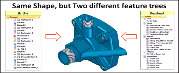
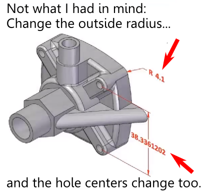
What is the failed promise of parametric CAD? In short, model reuse.

It’s a lot more difficult than it ought to be, for a variety of reasons. Several months back, I wrote a series of articles discussing those reasons, as well as some of the solutions that have come up over the years.  What was missing from the series was a final chapter; a detailed description of what could prove to be a viable solution to problems with model reuse: the resilient modeling strategy.

The resilient modeling strategy (RMS) is the brainchild of Richard “Dick” Gebhard. I wrote about Dick last June, in the article A Resilient Modeling Strategy. He’s a low-key guy with deep experience and serious expertise in the practical use of MCAD software. Over his career in CAD, he’s been a reseller for CADKEY, Pro/E, and most recently, Solid Edge.

RMS is a best practice for creating CAD models that are stable and easily reusable (even by inexperienced users.)  It can be learned and easily used by typical CAD users, it preserves design intent in models, and provides a mechanism by which managers or checkers can quickly validate a model’s quality.

Resilient Modeling Strategy

When Dick first started thinking about the concepts that make up the resilient modeling strategy, it was natural that it was in the context of showing the advantages of Synchronous Technology (The Siemens PLM brand name for its version of direct modeling.) In our discussions about RMS over the last year or so, I pointed out that, while I thought that RMS did indeed demonstrate the benefits of hybrid history/direct modeling in Solid Edge, for it to be taken seriously, and not be unfairly dismissed as a marketing initiative for Solid Edge, it needed to work with a wide variety of MCAD tools. I think Dick got where I was coming from, because he’s continued to refine and generalize RMS, with feedback from users of a number of MCAD systems.

In its current incarnation, RMS works particularly well with Solid Edge, as might be expected, but also works very well with Creo, NX, CATIA, and IronCAD (all of which are hybrid history/direct systems.) Further, with a few modifications, it can provide compelling value with SolidWorks, Inventor, and Pro/E (all of which are primarily history-oriented systems.)

It’s significant that RMS is also free to use. While Dick is available to provide presentations, seminars, and training, he has not attempted to patent, or keep as trade secrets, the underlying concepts of RMS. (He does claim a trademark on the term “Resilient Modeling Strategy,” which means that organizations offering commercial training on RMS will need to get Dick’s OK to use the term.)

Dick has posted an introductory presentation on RMS at resilientmodeling.com. While the entire presentation is 20 minutes long, the first 3-1/2 minutes cover the problems that people invariably experience when reusing or editing history-based CAD models. Watching that much will likely convince you to watch the rest.

On Wednesday, November 20, at 10:00 AM PST, Dick will be hosting a webinar on RMS. It’s scheduled to last just 30 minutes, with the emphasis on content, not hype. If you’re a serious CAD user or a CAD manager (or, for that matter, you work for an MCAD developer), it’ll be well worth your time to attend.

TL;DR: Resilient Modeling Strategy is a best practice for creating high quality reusable 3D MCAD models. It works with many CAD systems, it’s easy to learn and use, and it’s free. Big payoff for MCAD users. 

Presentation at resilientmodeling.com

Register for Nov 20 webinar on Resilient Modeling


Filed Under: Catia, Creo, Evan Yares, Featured, Inventor, News, Pro/Engineer, Siemens PLM, SolidWorks Tagged With: 3D CAD, Catia, Dassault Systemes, Evan Yares, Inventor, IronCAD, PTC, Siemens PLM, Solid Edge, SolidWorks

Should you buy your CAD software—or rent?

February 2, 2012 By Evan Yares 4 Comments

CAD software isn’t cheap. A mainstream 3D CAD program will set you back thousands of dollars upfront, and a bunch more in annual maintenance charges.

The cost can be daunting. But what if there was a way to spread it out, and pay as you go?

Rental: An idea that’s been tried.

A dozen years or so ago, a relatively new CAD vendor, Think3, started offering their CAD software on a monthly rental basis. It was an intriguing idea, but it would have worked better had Think3’s software been more mature at the time. People tend not to renew rentals when the software doesn’t do what they need.

More recently, Ashlar-Vellum has offered their line of CAD programs under a number of licenses, including permanent, one-year, and monthly rental. Though Ashlar’s software is highly respected (especially by industrial designers), the company isn’t one of the big players in the CAD business.

Solid Edge Design 1Recently, Siemens PLM, which is one of the big players, revisited the idea of renting CAD software—but with a new twist. They partnered with Local Motors, a company that does crowd-sourced design of cars. Members of the Local Motors community can rent (actually “subscribe,” but with enough flexibility that it seems like renting) a special version of Solid Edge called Design 1, for $19.95 per month.

Solid Edge Design 1 is a capable CAD program, incorporating Siemens’ Synchronous Technology direct modeling tools. It’s no toy.

There are a couple of key things that make this initiative interesting. First, Solid Edge Design 1 is capable of effectively importing and editing solid models imported from most common CAD systems, including SolidWorks and Pro/E. Second, Design 1 is a direct modeler (it doesn’t include history-based modeling), so it’s quite a bit easier for a normal person (as opposed to a CAD guru) to get up and running on than systems such as SolidWorks and Pro/E (or, for that matter, the full-blown version of Solid Edge.)

Simplicity can be compelling: Solid Edge Design 1 can work with the data you have, doesn’t take a whole lot of time to learn to use, and only costs 20 bucks a month, with no long-term commitment.

One good question might be why Siemens PLM is offering Design 1 through Local Motors, instead of directly. It’s probably because Jay Rogers, Local Motors’ CEO, came to Siemens PLM, and said “this is what we’re looking for.” Siemens PLM responded, saying “that sounds interesting. Let’s give it a try.”

The only real “catch” with Solid Edge Design 1 is that it’s really only intended to be used for Local Motors related projects. Its native CAD files can not be read by the commercial versions of Solid Edge (though, because it is a direct modeler, it can write perfectly good neutral files, such as IGES, STEP, and JT.)

Siemens PLM has recently gone beyond just offering a $20 per month version of Solid Edge to the Local Motors community. They’re now offering the full-range of Solid Edge versions, up to Solid Edge Premium, with full FEA simulation, wire harness design, pipe and tube routing, for rental prices ranging from $99.00 to $299.00 per month. These versions of the software can technical support from Siemens.

At first blush, $300 a month sounds like a lot of money. It might be, for a hobbyist who just wants some CAD software to play at designing cars. But, for a person who plans to use the tool for serious work, it’s not that much. Put it in context: A commercial license of Solid Edge Premium sells for on the order of $7,500 up-front, plus another $2,000 or so in annual maintenance fees.

To me, $300 per month for this software, including updates and direct support, seems like a bargain.

For small to medium size businesses, the ability to pay for software as an expense, rather than as a capital item, is pretty compelling. Even more compelling is the ability to control costs by adding or reducing CAD seats as needed.

Is software rental the wave of the future?

Software rental has three problems that CAD vendors don’t like: First, the revenue stream has to be recognized for accounting purposes as it comes in, rather than upfront. For publicly held corporations focused on reporting lots of revenue, that’s not very attractive. Second, it’s hard to pay front-loaded commissions and bonuses to salespeople on rentals. And third, there’s no guarantee that someone who is renting software will continue to do so. That is, it’s difficult to “lock-in” those customers (and their revenue) over the long term.

Siemens PLM could get away with this initiative for a few reasons: They limited it to Local Motors community members, so they can learn what works (and what doesn’t) without messing with their entire customer base. As Solid Edge is not the market sales leader, they’re more likely to displace competitive seats than their own. Since the Solid Edge product group is only a tiny part of the giant Siemens corporation, there’s not much risk that this program’s success or failure will impact their next quarter’s financial results (and stock price.) And, finally, they have enough confidence in their product to believe that a pretty reasonable percentage of the people who have a chance to use it will like it.

While the Siemens PLM/Local Motors partnership is probably a bit of an experiment, it’s encouraging. Anything that can make good CAD tools more affordable is likely to be popular with users.

Siemens PLM Systems

http://www.plm.automation.siemens.com

Local Motors

http://forge.local-motors.com


Filed Under: Evan Yares, Siemens PLM, Siemens PLM & Events Tagged With: 3D CAD, Licensing, Local Motors, Siemens PLM, Solid Edge

SpaceClaim: Sheet metal design for pirates?

January 25, 2012 By Evan Yares Leave a Comment

Let this be a warning to all CAD vendors: Don’t encourage your application engineers to “be creative and have fun.” You might end up with product videos such as this one:

All seriousness aside, SpaceClaim does have compelling sheet metal tools for people other than pretend pirates. And, unlike some older CAD programs, SpaceClaim is relatively fun to use – probably because it doesn’t make you “walk the plank” to get your job done.

What this video alludes to, without coming right out and saying it, is that SpaceClaim, as a direct modeling CAD system, lets you use whatever existing part geometry you may have, from just about any other CAD system, as a starting point for sheet metal design. So, if someone throws a part file at you, and asks you to turn it into sheet metal, you can get it done with minimum fuss – even if the original CAD file is a mess (as many are.)

In the last few years, SpaceClaim has been starting to make an increasingly large impact on the market, not just because it works well, but also because it doesn’t require users (or the companies they work for) to throw-out their existing CAD tools.

After this video was posted, Blake Courter, a SpaceClaim co-founder, commented on Twitter that this year’s marketing campaign for SpaceClaim “consists entirely of setting up booths at renaissance festivals.” I think he was kidding (though I wouldn’t be surprised to see SpaceClaim at Burning Man later this year.) Until then, you might try visiting their website.

SpaceClaim 

www.spaceclaim.com

Filed Under: Evan Yares, SpaceClaim, SpaceClaim News Tagged With: 3D CAD, Blake Courter, Direct Modeling, Funny, sheet metal, SpaceClaim

High-tech tools for a cool ride

January 23, 2012 By Laura Carrabine Leave a Comment

When Marcus Hays first heard about an electric bike, he was less than enthusiastic. Why load a bike with battery weight, turning the human motor into passenger in the process? That was 1995 and Hays was working with Lee Iococca to develop electric cars and bikes.

Electric bikes use less than 1,000 watts of total power and can be used on bike paths. When Hays first encountered these hybrid vehicles, most models were imported from a variety of countries. They relied on an injection molding manufacturing process which produced parts made of a variety of thermoplastics. While initially pleasing in appearance, the plastic parts raised questions of reliability and tended toward unsightly discolorations and dangerous cracks. “As an advocate for electric bikes,” said Hays, “I felt these problems had to be solved.”

To efficiently produce a more reliable and environmentally friendly electric bike, Hays’ company Pi Mobility took a minimalist approach. For Hays and his team, the longer a product will last is a key factor in making it more sustainable. Rather than rely on brittle plastics for a multitude of parts, Pi Mobility used an elegant, solitary arch of recycled aluminum for its bikes’ iconic frame. The recycled aluminum lasts longer than plastic and the batteries and electronic components reside safely within the aluminum tube rather than an injection molded plastic battery enclosure.

Recycled aluminum requires one-thirteenth the amount of electricity to produce compared to virgin aluminum. And, a Pi Mobility bikes produces 300 lbs of carbon dioxide per 12,000 miles of travel, making it 20-30 times more efficient than a motorcycle or cart. The single tube used in the PiCycle and PiMoto models’ battery agnostic design means they can conceivably handle any battery or chemical process that produces electricity, allowing for easy upgrades in the future.

Thanks to the less labor-intensive design of the single tube, Pi Mobility has been able to maintain production in the US and still be profitable. “We can form a tube in about 30 seconds,” said Hays. “With the help of Autodesk software, changes to the design can be embedded very quickly. Our manufacturing method offers very rapid scale at competitive prices, but it also reduces the required labor to a fraction of more traditional electric bikes. By producing our bikes locally, much of the transportation carbon that often affects even environmentally sustainable good can be eliminated.

The company’s testing program makes durability and sustainability its top priorities, before appearance. Pi Mobility seeks to combine all three elements at every opportunity. The Autodesk solution for Digital Prototyping helped the company to optimize its design and bring new products to market faster.

Hays said,” We use Inventor, Vault, Alias Design, and Showcase. Our design team took to the software immediately. After just three weeks the team produced a 3D digital prototype using Inventor. It proved that by increasing the diameter of our tube by a half inch, we could save $335,000.”

Pi Mobility

www.picycle.com

Autodesk, Inc.

www.autodesk.com


Filed Under: 3D CAD Package Tips, Autodesk, Autodesk News, CAD Blogs, Inventor Tagged With: 3D CAD, Alias prototyping, Autodesk, electric bikes Vault, Inventor, Marcus Hays, Pi Mobility, Showcase

Guitar maker speeds design process

January 19, 2012 By Laura Carrabine Leave a Comment

Fender Musical Instruments Corporation is a leading manufacturer of stringed instruments, including electric, acoustic, and bass guitars as well as guitar amplifiers. While the company handcrafted guitars and used 2D AutoCAD design tools for many years, the 2002 acquisition of the JACKSON guitar brand brought more complex geometry challenges that required 3D design technology to drive manufacturing.

Fender chose SolidWorks CAD software – first deployed on the JACKSON and FENDER STRATOCASTER lines and now used companywide – because it is easy to use, includes advanced surfacing capabilities, and integrates well with CAM applications. By deploying SolidWorks, Fender cut production time by 20% across the board, reduced the time required to shape guitar necks by 30%, eliminated many secondary operations, and increased production throughput with improved tooling.


SolidWorks

www.solidworks.com

Filed Under: 3D CAD Package Tips, CAD Blogs, CAD Package, SolidWorks, SolidWorks Blogs, SolidWorks News & Events Tagged With: 2D, 3D CAD, AutoCAD, Fender Guitar, SolidWorks

Athletic gear gets muscle

January 19, 2012 By Laura Carrabine Leave a Comment

Concept2, the world leader in rowing exercise equipment, uses KeyCreator software to design and develop its complete line of indoor rowers and oars, including the recently introduced Model E and the popular Concept2 ‘Model D’ rowing machine – voted  “Most Innovative Fitness Product” by Health Magazine. Concept2 rowing exercise equipment is used by 99% of the rowing clubs and school rowing teams throughout the world.

Concept2 was founded by Dick and Peter Dreissigacker in 1976. Fresh from Olympic training, the two brothers designed and created the first composite carbon fiber racing oars, and went on to prototype the world’s first wind-resistance indoor rower out of old bicycle parts. The Dreissigacker Racing Oars are now used by more than 70% of the rowing community. The Concept2 Indoor Rower has been redesigned and upgraded four times since the Model A was introduced in 1981. Today’s Model D and the recently introduced Model E both build on Concept2’s 26 years of experience in designing and manufacturing rowing machines.

“KeyCreator is integral to our design and manufacturing process,” said Jon Williams, chief engineer of Concept2. “The software enables us to quickly develop, test and iterate conceptual models. KeyCreator makes it easy to communicate those design ideas accurately to our supply chain partners.”

Responding to both customer feedback and rising manufacturing costs, Concept2 decided to evolve its overall rowing system. One area identified for a major design change was the flywheel enclosure. Now in its fifth generation of indoor rowing machines, Concept2 has moved the flywheel from an original unenclosed bicycle wheel to the current three-piece injection molded housing available in today’s Model D &  Model E. Concept2 engineers took advantage of KeyCreator to design current advancements into the Model D.

“When our customers requested greater battery life in the rowing machine monitor, Concept2 designed an efficient, non-contacting generator that powers the monitor as the machine is being rowed.  And when customers wanted a quieter flywheel mechanism, Concept2 used KeyCreator to experiment with different shape housing designs that delivered significant noise reduction,” added Williams.

Accurate exchange of CAD data is vital to Concept2. The Concept2 Indoor Rower has become the standard across the rowing community in part because of the high degree of comparability between scores achieved on individual rowing machines – ensuring that 2000 meters rowed on one Concept2 machine is exactly 2000 meters on another. This standardization has proven significant during races, such as those at the CRASH-Bs (indoor rowing championships).  The accurate exchange of CAD data between Concept2 and its partners guarantees standardization, regardless of which manufacturing plant or assembly plant is building a rowing machine or producing any part.

Concept2 is dedicated to providing the most innovative rowing products and programs to its customers.  That commitment depends on imagination and advancements in technology developed by the engineers using KeyCreator.

Kubotek

www.kubotekusa.com

Filed Under: 3D CAD Package Tips, CAD Industry News, CAD Package Tagged With: 3D CAD, Concept2, KeyCreator

  • Go to page 1
  • Go to page 2
  • Go to page 3
  • Go to page 4
  • Go to Next Page »

Primary Sidebar

3D CAD NEWSLETTERS

MakePartsFast

Follow us on Twitter

Tweets by 3DCADWorld

Footer

3D CAD World logo

DESIGN WORLD NETWORK

Design World Online
The Robot Report
Coupling Tips
Motion Control Tips
Linear Motion Tips
Bearing Tips

3D CAD WORLD

  • Subscribe to our newsletter
  • Advertise with us
  • Contact us
Follow us on Twitter Add us on Facebook Add us on LinkedIn Add us on Instagram Add us on YouTube

3D CAD World - Copyright © 2021 · WTWH Media LLC and its licensors. All rights reserved.
The material on this site may not be reproduced, distributed, transmitted, cached or otherwise used, except with the prior written permission of WTWH Media.

Privacy Policy