• Skip to primary navigation
  • Skip to main content
  • Skip to primary sidebar
  • Skip to footer

3D CAD World

Over 50,000 3D CAD Tips & Tutorials. 3D CAD News by applications and CAD industry news.

  • 3D CAD Package Tips
    • Alibre
    • Autodesk
    • Catia
    • Creo
    • Inventor
    • Onshape
    • Pro/Engineer
    • Siemens PLM
    • SolidWorks
    • SpaceClaim
  • CAD Hardware
  • CAD Industry News
    • Company News
      • Autodesk News
      • Catia News & Events
      • PTC News
      • Siemens PLM & Events
      • SolidWorks News & Events
      • SpaceClaim News
    • Rapid Prototyping
    • Simulation Software
  • Prototype Parts
  • User Forums
    • MCAD Central
    • 3D CAD Forums
    • Engineering Exchange
  • CAD Resources
    • 3D CAD Models
  • Videos

cam

Autodesk Adds CAM Capabilities to Fusion 360

May 22, 2014 By Barb Schmitz

Advances in digital design and rapid fabrication technology coupled with crowd funding are pushing the edge of what’s possible and empowering more people to transform their innovative designs into products. Autodesk has been quick to respond to this so-called “maker” trend and last week introduced Spark, an open software platform for 3D printing. The goal of Spark is to make it easier to 3D print your designs and control the printing process.

The company also announced plans to roll out its own 3D printer that will serve as a reference implementation for Spark. Together the company hopes this technology bundle will provide the building blocks that product designers, hardware manufacturers, software developers and materials scientists can use to continue to explore the limits of 3D printing.

Read more on Spark and the company’s overall 3D printing strategy in a blog, “Accelerating the Future of 3D Printing,” written by Carl Bass, Autodesk’s president and CEO. Also, check out Design World’s 3D printing expert, Leslie Langau’s take on the Spark announcement here.

Fusion 360: one-stop destination for design and manufacturing for entrepreneurs

Following on the heals of its 3D printing product announcements is Autodesk’s release of new CAM capabilities for Fusion 360. With the addition of CAM, users are another significant step closer to having a single, integrated tool with everything they needed to bring a product to market — from concept to manufacture.

Ideal for hardware starts-ups, small- and medium-sized businesses and students, Fusion 360 is a single cloud platform for form, function and fabrication, which enables users to design, test and fabricate all in one environment. Because it resides in the cloud, users can access design data in Fusion 360 anytime and anywhere from multiple devices, such as mobile devices, PCs or Mac.

Fusion 360 also makes collaboration easy by providing a common place and a single tool to collaborate on projects. Built-in data management tools help capture project history so users don’t have to worry about losing or recreating data.

By adding new CAM capabilities to its cloud-based Fusion 360 product, Autodesk hopes to become the single destination for product design and manufacturing for entrepreneurs.

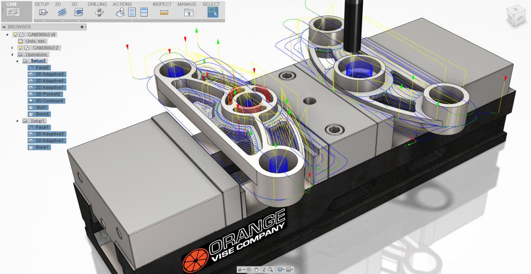
What’s new on CAM side?

The new CAM functionality will consist of 2.5 and 3-axis CAM on Windows 8. Additional enhancements include:

* Rendering: Improved render experience with new workspace, ray trace command and better performance.
* Better Output Options: Users are now able to export their Fusion 360 designs in OBJ and DFX file formats, and prep them for 3D printing with the power of Autodesk Meshmixer.

What makes this design platform ideal for smaller and mid-size companies and startups is the fact that it’s offered by monthly subscription. Check out information regarding the monthly subscription pricing here.

Filed Under: 3D CAD Package Tips, Autocad Blogs, Autodesk, CAM Tagged With: Autodesk, cam

Geometric Ships CAMWorks 2014 for Solid Edge

May 9, 2014 By Barb Schmitz Leave a Comment

Innovation is today’s CAD products is somewhat expected by users who constantly demand the next level of functionality. After all, designers and engineers are using modern CAD tools to design the next great product, or at least the next great version of a product. The same cannot necessarily be said on the CAM side, where progress to innovate tools has been slower.

As the costs of modern machining technology has dropped and become more accessible, more and more designers and engineers tasked with outsourcing prototyping or doing it in-house are getting more involved with the CAM side of the equation. They are also interfacing more frequently with the manufacturing personnel running CNC machines.

Crossing the CAD-CAM Divide

There’s traditionally been a bit of a divide between engineering and manufacturing, possibly a result of the fact that they “talk” different languages in that they use disparate systems. The format created by CAD programs doesn’t seamlessly transfer to the CAM program and engineers are often accused of “lobbing” models over to manufacturing for them to deal with.

To alleviate some of these issues, CAD-integrated CAM packages began to emerge. The goal was to create a CAD-like workflow for CAM so engineers and designers would not have to learn a whole new software system.

Yesterday, Geometric Ltd. announced the shipment of CAMWorks for Solid Edge users. The new version provides even tighter integration with Solid Edge, Siemens PLM Software’s 3D CAD software, to speed programming time and accelerate time-to-market.

CAMWorks is an embedded CAM program that is fully integrated with Solid Edge.

One of the software’s users, Tim Hoeing, a plant manager at H&M Tool & Die, is a big fan of the software’s feature-based approach. “The feature-based approach seems much more intuitive than the process of creating profiles and chains method,” says Hoeing. “The automatic feature recognition and tool path associativity helps reduce programming time by as much as ten times. And the knowledge-based machining will save machining strategies for future use, enabling faster turn-around times on new jobs.”

With this release, Solid Edge users will gain access to the full suite of CAMWorks modules, including Sync Manager and Sub Spindle operations manager to speed up CNC programming for complex multi-spindle, multi-turret mill turn machines.

In addition, with the 5-axis simultaneous machining module, users in the aerospace, medical device, and oil & gas industry have the ability to machine complex surfaces using advanced 4- and 5-axis machining centers. Furthermore, tool and die customers now have the ability to program the Wire EDM machines within the same environment as their milling operations instead of having to maintain different software for different purposes.

CAMWorks 2014 also adds new mill-turn capabilities along with 5-axis simultaneous machining and assembly-mode machining, enabling users to confidently and accurately create tool paths that avoid fixtures, clamps, and other necessary work-holding devices, which is essential for today’s complex machining centers.

For more on CAMWorks 2014, check out this page on the Geometric Ltd web site.

Barb Schmitz

Filed Under: CAM, News, Siemens Blogs, Siemens PLM Tagged With: cam, Siemens, Solid Edge

PartMaker Releases 3D CAD for CAM Software

April 22, 2014 By Barb Schmitz Leave a Comment

Problems and errors often arise when 3D CAD models are moved into the manufacturing environment. For years the various software systems used in design and manufacturing spoke different languages so 3D CAD models often needed to be translated or dumbed down before being used as input by CAM software, which often resulted in errors on the shop floor.

Bridging the CAD-to-CAM divide

PartMaker, a division of Autodesk’s Delcam unit, hopes to change all that by creating 3D CAD modeling software that generates the 3D engineering data that precision part manufacturers need to be productive without cluttering their work flow with tools they don’t need or use.

PartMaker Modeling 2014 is 3D CAD for CAM software that provides users with the ability to create 3D solid models from scratch as well as repair and modify any 3D engineering data. Touted to be the most powerful 3D CAD system available alongside a production-oriented CAM product, this new version offers a unique radial cut wizard for creating cylindrically wrapped part features as well as improved direct modeling and feature recognition functionality.

PartMaker Modeling 2014 is a 3D modeling tool developed specifically for the needs of CNC machinists.

What’s new?

The new functionality in PartMaker Modeling 2014 was designed specifically for users that make parts on turn-mill centers and Swiss-type lathes as it includes a wide variety of functionality for creating milled features on parts that are cylindrical in nature.

Other new features include:

* Unique radial cut wizard. This new feature allows for very quick and intuitive creation of solid cut features on cylindrical surfaces, which is particularly helpful for creating “wrapped” features on cylinders that typically require cylindrical interpolation programming when machined.

* Automated snapping both geometry and solid features to existing faces. This makes creating both milled and drilled features such as hexes, flats and holes of any orientation much faster than previous versions.

* Enhanced direct modeling functionality. Used for altering “dumb” solid models, or 3D models with no feature history created in other solid modeling systems.

* Merge faces command. This direct modeling feature allows a number of coincident but separate faces to be merged into a single face automatically, which makes altering or removing features attached to these faces much faster and more automated.

* Smart feature manager Allows solid features to be extracted automatically from dumb solids. Using the smart feature manager, you can also control and filter which feature sets, such as just holes, are extracted from a dumb model.

* New extrude functionality. Improved functionality for extruding multiple regions with hollow shapes automatically.

To get more information on PartMaker Modeling 2014, check it this page on the PartMaker web site.

Barb Schmitz

Filed Under: Autocad Blogs, Autodesk, CAM, News Tagged With: 3D CAD, cam

Autodesk Ships Integrated CAM Package For Inventor

April 8, 2014 By Barb Schmitz Leave a Comment

There has been a real need in the manufacturing industry among users to have a tightly integrated CAM package that works hand in hand with users’ CAD systems. Users wanted CAM functionality but didn’t want to learn a whole new tool. Today, Autodesk announces that Inventor users now have such a package.

Autodesk got to this point after a key acquisition in October 2012 of HSMWorks technology, which was originally developed for SolidWorks users. Though there was skepticism in the market–and fear among HSMWorks users–regarding what the company’s real intentions were with the technology, Autodesk committed to continue development of the technology and announced plans to integrate it into the entire portfolio of desktop and cloud-based products.

An integrated CAM product for multiple users

HSM 2015 will help machinists, designers and engineers turn their Inventor models into manufacturable parts by generating machining tool paths from directly within Inventor.

Inventor HSM 2015 includes a full license of Inventor 2015 software, so users would have a complete CAD/CAM package with integrated design-to-manufacturing capabilities.

Inventor HSM includes the following features:

* Flexible 2.5D, 3D, and 3+2 toolpath options and settings for the best possible surface finish
* Simulation tools that help users verify the machining process before CNC programs are run on a machine * Highly customizable post-processors and a powerful CNC editor that enable users to tailor their programs to their CNC machine.

Filed Under: Autodesk, Autodesk News, News Tagged With: cam, Inventor

Hot rod engineering workstations

February 20, 2012 By Evan Yares Leave a Comment

When I was barely a teenager, in the early ’70s. I became interested in car magazines. In the back of some of those magazines, I’d often see ads for a company called Baldwin/Motion Performance. They sold brand new hot-rodded Camaros that were guaranteed to run 11.50 second or faster quarter miles at the drag strip. Baldwin/Motion Performance Camaros represented the epitome of tuner-built hot rods. They were fast enough that, according to Super Chevy magazine, you could buy one, and, with no further tuning, win the A/MP class at the Winternationals.

During the same period, other companies also sold fast Camaros. Though GM’s official policy in the late 60’s and early 70’s was that they didn’t support drag racing, there was a way to get nearly drag-ready cars, if you knew the trick. A few dealers, notably Yenko Chevrolet, managed to get Chevrolet to install Corvette 427ci L-72 engines in Camaros, through the “central office purchase order” process. These factory hot rod COPO Camaros came with a full factory warranty. Nearly perfect examples have sold for over $2.2 million USD at auction.

Muscle cars have little to do with CAD, but I was reminded of these cars, at least by analogy, when I was at the SolidWorks World 2012 show, in San Diego, last week.

While there, I attended a press conference announcing HP’s new Z1 engineering workstation. This machine is sort of analogous to a factory hot rod. It comes with a stunning 27” built in display, a quad-core Intel Xeon processor, NVIDIA Quadro graphics, and uses ECC (error correction code) memory—which is particularly desirable for critical engineering software applications (See Wikipedia’s entry on ECC memory for background on this.)

There’s no doubt that the Z1 costs more than a typical commodity PC. But, for people doing serious CAD, CAE, or CAM work, the performance and reliability the system offers is worth the premium.

While at SolidWorks World, I also had a chance to chat with Rick Krause, CEO of BOXX Technologies. BOXX makes what could be considered the equivalent of a tuner-built hot rod. Their 3DBOXX 3970 XTREME workstation is designed to provide the best performance possible for serious 3D CAD work. That is, it’s performance isn’t tuned for doing spreadsheets and web browsing (which benefit from multiple core processors), it’s tuned for doing serious CAD work (which requires fewer, but faster cores.)

Let’s go back to the car analogy: Yenko Chevrolet sold stock Camaros, with the biggest and best engines GM offered. Baldwin Chevrolet sold hot-rodded Camaros, also with the biggest and best engines GM offered, but tuned to put out over 500+ horsepower (while still being streetable.)

The HP Z1 engineering workstations use Intel’s biggest and best processors. The BOXX XTREME workstations also use Intel’s biggest and best processors – tuned (overclocked) for the most horsepower.

BOXX doesn’t really like to use the work “overclock,” because it implies that they’re pushing the processor past it’s design spec. BOXX works closely with Intel, to make sure they stay within the processor design specs. Since they use liquid-cooling, they can push the processor faster, without reliability problems. Their workstations are backed-up by a 3 year warranty, and, in their history of selling overclocked systems, they’ve never experienced a processor failure.

If you’re a serious CAD, CAE, or CAM user, and you can out-run your current computer, you need to take a serious look at getting a factory-built or tuner-built hot rod computer.

HP Z1 Workstation

BOXX Technologies 3DBOXX 3970 XTREME Workstation

 Photo courtesy Baldwin-Motion


Filed Under: CAD Hardware, Evan Yares Tagged With: BOXX Technologies, cad, CAE, cam, Engineering Workstation, Evan Yares, HP

VISI version 18 is new and improved

July 16, 2010 By Laura Carrabine Leave a Comment

Software features include VISI modeling and VISI shoes. CAD enhancements include an updated GUI with improved user interaction, new Mesh tools, new model deformation tools for model manipulation and multi-page splitting for the 3D and plotview environment.

VISI Mold enhancements include improved integration CADENAS PartSolutions V9, faster interference checking between bodies, and improvements to user elements with a new family option and a new loading option with smart positioning.

VISI Progress enhancements include a new animation of the forming process, an automated method to apply blend radii to sharp edges, a re-development of ribs and bosses, and the introduction of suspenders managements within the strip.

CAM enhancements focus on improving the overall usability and consolidating the existing functionality with improvements on performance, Compass Technology, and the kinematic simulation.

VISI Flow analysis and simulation can be calculated and validated directly inside VISI.

Finally, a collaboration of Vero and Camtek technologies make up VISI PEPS-Wire. It introduces automated 2 and 4-axis feature recognition, improved geometry tools, and a platform for combined milling and wire EDM cutting strategies.

Vero Software
www.vero-software.com

Filed Under: 3D CAD Package Tips Tagged With: 3D, cam, Camtek, EDM, PartSolutions, Vero, VISI

CAM – Face classification

July 13, 2010 By Laura Carrabine Leave a Comment

To explain the principle, if you simply break a 3D curve into equal length lines, the deviation of the lines from the curve would change as the curvature became larger and smaller. However, using a chordal deviation, the operator defines the maximum distance between the chord and the original geometry. The major benefit of using a chordal deviation to control the 3D mesh is that you have a consistent, predictable deviation.

You may then ask why not a set of very small chordal tolerance? In theory you can but this does effect the data size and also produces extra CNC code when it may not be necessary. You also have to be aware that on older machines without high speed controllers, the extra movements could choke the machine if the feed rates are not reduced. Dropping the feed rate is non-productive and reducing the accuracy means more time polishing and a less accurate part.

Okay, with the problem explained, the following tip shows how it is possible to improve this situation by defining a different set of chordal parameters based on face type.

When defining the piece parameters, the general chordal tolerance and angular tolerance is applied to the complete model. However, there is a face classification box that open an additional set of parameters that separates the tolerances for planar and radiused faces.

If the face classification box is NOT active, the general tolerances are applied to the complete model.

If the face classification box IS active, additional tolerance parameters become active. This allows the operator to separate the model into 3 tolerance bands – planar faces, radiused faces, and the general faces.

The major advantage of the mesh optimization is that it allows the operator to be more creative with the machining tolerances and still retain a sensible model size.

If you use the face classification option within the piece definition, it is then possible to graphically display and sort by face type when displaying the mesh within the piece manager. Even at this point within the tree structure, it is possible to select an individual face and define a different chordal and angular tolerance. If individual face parameters are applied, the face will be displayed with a different icon within the tree.

Vero Software
www.vero-software.com

Filed Under: 3D CAD Package Tips, CAD Hardware Tagged With: 3D, cam, chordal, CNC, Vero Software

Vero help with Artega GT ‘supercar’ production

July 13, 2010 By Laura Carrabine Leave a Comment

DECS GmbH are specialists in the design and manufacture of interior and exterior trim composite components for the automotive industry. Reference customers include Audi, BMW, Lamborghini, Mercedes, and Porsche. DECS GmbH embraces technology and firmly believes in process optimization. It is a combination of these factors that helped their latest project, the Artega GT succeed, and cause a stir in the automotive world.

The Artega GT is a mid-engined, rear wheel drive, high-performance sports car designed by Henrik Fisker, the man responsible for the much celebrated Aston Martin Vantage and the sweeping lines of the BMW Z8. The two-seater GT has an aluminum space frame and carbon fiber reinforced body. Providing the power is a Volkswagen-sourced 3.6L V6 engine reaching 60mph in less than five secs.

Within the framework of this project, DECS GmbH contributed to the manufacture of the front bonnet, tailgate, and roof.  Ulrich Krämer, Managing Director of DECS GmbH explains how the project started. “Artega originally contacted us because we have been involved in a number of projects with other prestige automotive clients and possess the skill and knowledge required for the development of composite components. For the initial pilot project, we first created five parts using a prototype tool. We were then invited to participate in the second phase in which we produced a pre-series set of tooling for the front bonnet and tailgate for testing. After successful pre-series testing, we now manufacture the complete suite of production parts for the front bonnet, tailgate, and roof.”

DECS GmbH produces its polyurethane-based composite components using a honeycomb core. This is especially relevant in the development of automotive interiors as the potential weight reduction is extremely attractive to car manufacturers. Natural fiber-reinforced polyurethanes are being used more and more in the automotive industry and it is now possible to produce parts with wall thicknesses of 1.5 – 2.0 mm – depending on the unit weight of the natural fiber mat used. These end products weigh about 45% less than products created using conventional injection molding materials.

One example of process optimization is the use of Huber & Grimme gantry milling machines, which are equipped with efficient two shaft spindles and tandem work-tables for multi-axis part trimming. Once the body panels are removed from the tool, they are placed onto jigs and fixtures for part trimming and additional CAM operations. All 5-axis operations are programmed using VISI Machining from Vero Software and posted using a Siemens 840D controller. Due to the complex nature of multi-axis machining, NC programs are also simulated prior to running on the shop floor. The simulation checks against the physical machine limits and ensures process-safe tool paths.

The relevant jigs and fixtures are also designed using VISI software and produced at DECS. “VISI is the ideal tool for the construction of the trimming jigs”, explains Krämer. “One advantage is the ability to constantly switch between solid and surface technologies. This is vitally important to us and allows us to follow a flexible design path. VISI provides interfaces to all the significant data formats such as CATIA, UG, Pro/E, STEP, IGES, and SAT and this allows us to handle our clients native CAD data with confidence.”

VISI has been in use at DECS GmbH since 2005 when the software was provided as a solution for simultaneous 5-axis milling to solve a problem that involved the complicated trimming of plastic parts with undercut positions that could not be could be processed with water-jets.

Vero Software
www.vero-software.com

Filed Under: 3D CAD Package Tips Tagged With: Aston Martin, Audi, BMW, cad, cam, Catia, DECS GmbH, Lamborghini, Mercedes, Porsche, Pro/E, UG, Vero, VISI Machining, Volkswagen

Alibre Announces Permanent Price Cuts

March 3, 2010 By 3DCAD Editor Leave a Comment

Richardson, TX – Alibre, Inc. announced price cuts to its line of 3D CAD software. Alibre develops and markets Alibre Design™, a powerful parametric 3D/2D design application. The entry level package, Alibre Design Standard, is now $97 (down from $1000) and includes full 3D design and associative 2D drawings, along with Alibre Translate (formerly $499), an import/export suite that supports Solidworks®, Pro/Engineer™, Autodesk® Inventor™, SolidEdge™, Catia®, and Parasolid formats in addition to all neutral CAD formats.

All levels of Alibre Design software and software maintenance have been reduced in price, positioning Alibre products as the extreme value leader in the design and manufacturing industries. The product levels, pricing, and optional software maintenance prices are:

Alibre Design Standard – $97 (software), $97 (1 year support and updates) Includes parametric 3D design (parts and assemblies), 2D drafting, import/export options for native CAD formats and neutral formats, and 3D PDF creation.

Alibre Design Professional – $497 (software), $147 (1 year support and updates)Adds sheet metal design module, push/pull editing, standard part libraries, design configurations, photorealistic rendering, and single part FEA analysis.

Alibre Design Expert – $997 (software), $197 (1 year support and updates) Adds Windows-integrated data/product management solution, integrated physics-based motion analysis, an integrated CAM solution, and Machinist Toolbox, a shop utility offering features such as unit conversion, speeds and feeds, trig calculations, and reference materials.

The new price points position Alibre products to enter new markets – primarily the individual and home user – while still providing the professional grade tools higher end users expect. The DIY phenomenon, as covered by many publications such as Wired, the New York Times, and the Wall Street Journal, presents a huge opportunity for vendors willing to cater to lower price points. People are designing things for themselves, either as products or as side projects, and benefit from professional design tools. It’s been the case in the past that they simply could not afford them.

Alibre, Inc.
www.alibre.com

Filed Under: 3D CAD Package Tips, Alibre Tagged With: 3D, Alibre, cad, cam

Primary Sidebar

3D CAD NEWSLETTERS

MakePartsFast

Footer

3D CAD World logo

DESIGN WORLD NETWORK

Design World Online
The Robot Report
Coupling Tips
Motion Control Tips
Linear Motion Tips
Bearing Tips

3D CAD WORLD

  • Subscribe to our newsletter
  • Advertise with us
  • Contact us
Follow us on Twitter Add us on Facebook Add us on LinkedIn Add us on Instagram Add us on YouTube

3D CAD World - Copyright © 2022 · WTWH Media LLC and its licensors. All rights reserved.
The material on this site may not be reproduced, distributed, transmitted, cached or otherwise used, except with the prior written permission of WTWH Media.

Privacy Policy